Table of Contents
Advertisement
Quick Links
Advertisement
Table of Contents

Related Manuals for Elektron KERCOMET 170


Summary of Contents for Elektron KERCOMET 170
- Page 1 Made in Germany Operation Manual KERCOMET 170 MULTIMIG 150 MIG / MAG - Welding machine Item-No: 327 972 Be sure you have read and understood this operating Revision: 1.0 - Original manual before you carry out any works on and/or with this Version: 31.01.2013...
- Page 2 © BlitzRotary GmbH Branch Bremen Hinterm Sielhof 22 D-28277 Bremen Germany Phone: +49 (0)421 / 54 90 6 - 906 Fax: +49 (0)421 / 54 90 6 - 19 E-Mail: vertrieb@elektron-bremen.de Internet: www.elektron-bremen.de Release: BlitzRotary GmbH Branch Bremen...
-
Page 3: Table Of Contents
Table of contents 12.8 Changing the wire electrode Machine elements Start-up Explanation of symbols 13.1 Control console KERCOMET 170 and Meaning of the symbols in the operation MULTIMIG 150 manual 13.2 Control console KERCOMET 210 Meaning of the symbols on the machine 13.3 Current/voltage display... -
Page 4: Machine Elements
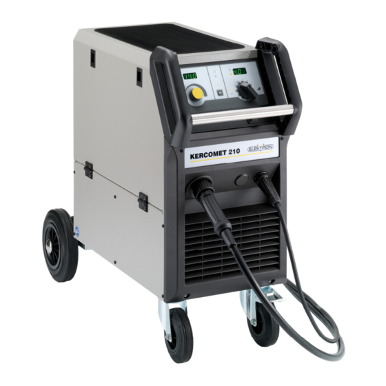
KERCOMET 170 210, MULTIMIG 150 Machine elements Machine elements Fig. 1: Machine elements Safety chain for gas Hoisting points Mains cable Mains voltage changeover-switch Some depicted or described acces- (on switch able units only) sories are not included in the Gas hose scope of delivery. -
Page 5: Explanation Of Symbols
KERCOMET 170 210, MULTIMIG 150 Explantion of symbols – Safety precautions Explanation of symbols Meaning of the symbols in the Meaning of the symbols on the operation manual machine Danger to life and limb! Danger! If the danger warnings are disre-... -
Page 6: General Regulation Of Use
KERCOMET 170 210, MULTIMIG 150 General regulation of use Do not use this machine to thaw frozen Please use a suitable extraction water pipes or cables. system gases cutting fumes. Always wear breathing ap- In closed containers, under cramped con-... -
Page 7: Ambient Conditions
If other equipment is disturbed it may be of the equipment carried out regularly in necessary to provide additional shielding. accordance with VDE 0544-4. ELEKTRON recommends inspection intervals of 12 months. The affected area can be bigger than your A safety inspection must also be carried out premises/property. -
Page 8: Setup And Transport
KERCOMET 170 210, MULTIMIG 150 Setup and transport 10 Setup and transport Danger of injury due to the de- vice falling over and crashing! When transporting using mechani- cal lifting equipment (e.g. crane, etc.), only the hoisting points shown here may be used. Use suitable load-carrying equipment. -
Page 9: Brief Operating Instructions
KERCOMET 170 210, MULTIMIG 150 Brief operating instructions 11 Brief operating instructions Select the 2-stroke mode using the button A detailed description can be found chapter. „Before start up“ Page 10 and chapter. „Start up“ Select the thickness of material to be Page 16. -
Page 10: Before Start-Up
KERCOMET 170 210, MULTIMIG 150 Before start-up 12 Before start-up 12.1 Connecting the torch Performance values are limited in Connect the central connector 17 of the 230 V mode, i.e. max welding torch to the central socket 11. power is limited to 2/3 of the values stated in technical data. -
Page 11: Insert The Welding Wire Spool
KERCOMET 170 210, MULTIMIG 150 Before start-up 12.5 Insert the welding wire spool 12.6 Thread the wire electrode in Unscrew the contact tip of the torch. Danger to life and limb and fire hazard due to glowing welding Open side panel. -
Page 12: Connecting The Inert Gas Cylinder
KERCOMET 170 210, MULTIMIG 150 Before start-up Fig. 10: close 2-roll feed Contact pressure Wrong wire feed Correct too high roller Fig. 13: Wire feed rollers Note for wire feed unit with 4 rollers: Adjust the contact pressure of the wire feed... - Page 13 KERCOMET 170 210, MULTIMIG 150 Before start-up Set the gas quantity using adjusting screw 35 of the pressure reducer 13. The gas quantity will be displayed on the flow meter Rule of thumb: Gas volume = wire diameter x 10 l/min.
-
Page 14: Changing The Wire Electrode
KERCOMET 170 210, MULTIMIG 150 Before start-up 12.8 Changing the wire electrode Wire feed spiral: (for steel or flux-cored Change the wire feed rollers. Select the wire) most suitable rollers for the application. Remove the existing wire feed spiral or plastic core and insert the new wire feed spiral. - Page 15 KERCOMET 170 210, MULTIMIG 150 Before start-up Fig. 17: Wire feed Central socket 17 Central connection (torch) 25 Wire feed roller 38 Retaining nipple (=clamp) of the plastic liner for 4.0 mm and 4.7 mm outside diameter 39 O-ring 40 Union nut...
-
Page 16: Start-Up
KERCOMET 170 210, MULTIMIG 150 Start-up 13 Start-up 13.1 Control console KERCOMET 170 and MULTIMIG 150 Fig. 17: Control console KERCOMET 170 and MULTIMIG 150... - Page 17 KERCOMET 170 210, MULTIMIG 150 Start-up 57 Step switch material thickness / welding 45 Symbol wire feed step lights up in the 7-segment display 47 if the by setting the step switch, for approx. 2 wire feed is displayed in m/min or as seconds the material thickness alt.
-
Page 18: Control Console Kercomet 210
KERCOMET 170 210, MULTIMIG 150 Start-up 13.2 Control console KERCOMET 210 Fig. 19: Control console KERCOMET 210... -
Page 19: Current/Voltage Display
KERCOMET 170 210, MULTIMIG 150 Start-up 57 Step switch material thickness / welding 45 Symbol wire feed voltage lights up in the 7-segment display 47 if the for adjusting the material thickness alt. the wire feed is displayed in m/min. -
Page 20: Characteristic Connection
KERCOMET 170 210, MULTIMIG 150 Start-up 13.4 Characteristic connection Fig. 20: Characteristic table and selection knob • Is material-wire-gas combination The characteristic selection knob 65 and the nullified. Wire feed and welding voltage can corresponding table are in the wire feed be set manually. -
Page 21: Main Parameters
Secondary parameters The 7-segment display 47 displays the secondary parameter code and value al- ternately ( KERCOMET 170 / MULTIMIG 150 The 7-segment display 47 displays the sec- ondary parameter value, the 7-segment display 55 displays the secondary param- eter code (... -
Page 22: Special Functions
KERCOMET 170 210, MULTIMIG 150 Start-up 13.7 Special functions 13.8 Reset setting Gas test Master reset Turn the unit OFF using main switch 9. Attention! All personal settings Press the torch key and keep it pressed. will be lost. Turn the unit ON using main switch 9. -
Page 23: Messages
KERCOMET 170 210, MULTIMIG 150 Messages 14 Messages During operational faults / malfunction, the 7- As long as there is an error code on segment display 47 displays an error code. display welding is not possible. Code Error description Note... -
Page 24: Troubleshooting
KERCOMET 170 210, MULTIMIG 150 Troubleshooting 15 Troubleshooting Fault Possible cause Rectification Torch becomes too hot Contact tip not tightened properly check Torch switch has no function Union nut from torch hose pack to central Tighten the union nut when actuated... - Page 25 KERCOMET 170 210, MULTIMIG 150 Troubleshooting Fault Possible cause Rectification Inert gas missing Gas cylinder empty Replace Torch faulty Check and replace if necessary Pressure reducer dirty or faulty Check and replace if necessary Gas cylinder valve faulty Replace gas cylinder...
-
Page 26: Repair And Maintenance
KERCOMET 170 210, MULTIMIG 150 Repair and maintenance 16 Repair and maintenance Screw the two side panels onto the machine Please heed the current safety and accident prevention regu- back again lations during all maintenance and repair work. Never make repairs or technical... -
Page 27: Technical Data
KERCOMET 170 210, MULTIMIG 150 Technical Data 17 Technical data Technical data KERCOMET 170 KERCOMET 210 MULTIMIG 150 Welding range (I …I 15…170 25…210 15…150 2min 2max Welding range (U …U 15,3…22,5 15,3…24,5 14,8…21,5 2min 2max No-load voltage 16,7…38,0 14,5…40,3 14,4…26,9... -
Page 28: Options And Accessories
KERCOMET 170 210, MULTIMIG 150 Options and accessories 18 Options and accessories 18.1 Torch holder Fig. 21: Torch holder assembly left Fig. 22: Torch holder assembly right Order number: 420 958 Order number: 420 959 19 Disposal In accordance with European Council Directive Only for EU countries. -
Page 29: Schematic Kercomet 170
KERCOMET 170 210, MULTIMIG 150 Schematic 21 Schematic KERCOMET 170... -
Page 30: Schematic Kercomet 210
KERCOMET 170 210, MULTIMIG 150 Schematic 22 Schematic KERCOMET 210... -
Page 31: Schematic Multimig 150
KERCOMET 170 210, MULTIMIG 150 Schematic 23 Schematic MULTIMIG 150... - Page 32 H i n t e r m S i e l h o f 2 2 D - 2 8 2 7 7 B r e m e n Phone +49 / (0)421 / 54 90 6-906 +49 / (0)421 / 54 90 6-19 vertrieb@elektron-bremen.de www.elektron-bremen.de...
Need help?
Do you have a question about the KERCOMET 170 and is the answer not in the manual?
Questions and answers