Table of Contents

Subscribe to Our Youtube Channel
Related Manuals for Elektron MULTISPOT M80


Summary of Contents for Elektron MULTISPOT M80
- Page 1 Operating instructions MULTISPOT M80 Resistance Welder Be sure you have read and understood this operating manual before you carry Item no. 322921 out any works on and/or with this Revision: 3.0 - Translation equipment. Version: , March 2010...
-
Page 2: Table Of Contents
Contents page Warning notes – explanation of symbols Description of equipment and overview Start-up Assembly of power supply unit and trolley Compressed air connection Mains power supply connection Checking the mains voltage drop during welding Malfunction indicator Applications Technical data Working with spot-welding tongs Preparation of welding area Spot-welding with the tongs... -
Page 3: Warning Notes - Explanation Of Symbols
Warning notes – explanation of symbols Caution! Please note the following when using resistance welding units: The power supply unit and leads of the welding gun and the spot welding tongs generate a powerful electromagnetic field when in use. Electromagnetic fields can cause irritations of sense organs, nerve and muscle cells as well as malfunctions in physical aids (hearing aid, pacemaker etc.), electronic devices and data storage units. - Page 4 Tool selecting keys (manual) see Appendix Gun functions selecting keys Sheet thickness selecting keys Fine adjustment keys time +/– Tools Tongs, pulse welding Tongs, spot welding QUICKSPOT AIRPULLER Working with gun Push spot welding Stud welding Beat-out with washers, T-pins, riveting dies High-speed planishing hammer Anneal/shrink Sheet thickness selector...
-
Page 5: Description Of Equipment And Overview
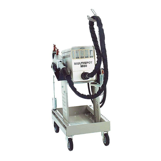
Description of equipment and overview The MULTISPOT M80 resistance welding unit is designed for the special requirements of motor vehicle body repair. The power source is controlled by a micro-processor. After selecting the operating mode and the sheet steel thickness, the current and weld time will be assigned automatically and –... - Page 6 - 4 -...
-
Page 7: Start-Up
Compressed air connection Connection to a compressed air supply is necessary for operation of the MULTISPOT M80 in conjunction with the spot welding tongs! The connection with adjustable filter/pressure reducer (65) is located on the back of the power supply unit (68). -
Page 8: Mains Power Supply Connection
63 A automatic circuit-breaker Checking the mains voltage drop during welding If the full performance of the MULTISPOT M80 is to be obtained, the mains voltage drop during welding must be kept as small as possible. The full test is described on Page 35, Chapter 11.3: ... -
Page 9: Malfunction Indicator
Malfunction indicator The red LED (14) indicates thermal overloading of the spot-welding tongs/spot- welding gun. While the LED (14) is glowing, it is not possible to continue welding with the tool connected. The unit is ready for use again after the LED (14) has extinguished. -
Page 10: Applications
Applications Welding capacity: Compressed-air pressure 8 bar Electrode arm 120 mm Programme switch Material Sheet thickness Function in mm Pulse welding with pneu- matic spot welding tongs sheet steel 3.0 + 3.0 Spot welding with sheet steel 2.0 + 2.0 spot welding tongs pneumatic galvanized steel 1.5 + 1.5... -
Page 11: Technical Data
Technical data Power supply unit Supply voltage 400 V (380-415 V) 230V (190-240 V) Slow fuse 32/35 A* 63 A* Mains frequency 50/60 Hz 50/60 Hz Power supply cord 14.7 kVA 14.7 kVA Max. welding capacity 45 kVA 45 kVA Open-circuit voltage 12 V 12 V... - Page 12 Spot welding tongs Electrode arm, stationary, 20 x 20 mm (square) Electrode arm, movable, 20 x 20 mm Welding electrodes with caps Momentary contact button Handle groove Release button for movable electrode arm Welding cable Electrode arm receptacle - 10 -...
-
Page 13: Working With Spot-Welding Tongs
Working with the spot-welding tong Caution! Switch off power supply unit or set to “push spot welding” mode during breaks or when changing electrodes or adjusting electrode spacing! Otherwise danger of crushing! – Insert the central plug of the spot welding tongs – with arrow pointing upwards –... - Page 14 - 12 -...
-
Page 15: Spot-Welding With The Tongs
Spot-welding with the tongs Caution: Electromagnetic fields! Wear protective goggles and gloves! Electrodes heat up! Flying sparks! – Switch on unit with mains switch (66). – Connect unit to the compressed air supply. Ensure sufficient compressed air pressure, operating pressure is 8 bar! If necessary, adjust pressure with the filter pressure reducer (65). - Page 16 - 14 -...
-
Page 17: Pulse Welding
Pulse welding Caution: Electromagnetic fields! Wear protective goggles and gloves! Electrodes heat up! Flying sparks! This mode is used for spot-welding sheet metal of 2 x 1.5 mm or more, such as e.g. frame parts and gusset flanges. Preparations: – Ensure precise fitting of the sheets to be welded –... - Page 18 Welding gun Button of welding gun Grounding cable Copper shoe Lever clamp Connection piece - 16 -...
-
Page 19: Operating The Welding Gun
Operating the welding gun Preparation: – Insert the central plug of the welding gun (33) into the central socket (63) until limit stop. Arrow on the plug pointing upwards. – The unit will switch automatically to the “gun” symbol. – Select the “gun”... - Page 20 - 18 -...
-
Page 21: Push Spot Welding
Push spot welding Caution! Electromagnetic fields! Wear protective goggles and gloves! Electrodes heat up! Flying sparks! Only use the mode “push spot welding” is the area to be welded cannot be reached with the spot welding tongs! – Grind sheet surface and the area between the sheets until completely bare. - Page 22 Contact piece UB Pulling tool - 20 -...
-
Page 23: Pulling-Out Dents With Washer
Pulling-out dents with washer – Grind the damaged area to a bright metal finish. – Insert contact piece (40) into welding gun. – Select “washer” mode with keys CD. – Select sheet thickness with keys EF (Sheet steel thickness more than 2 x 1.5 = 3 mm cannot be selected). –... - Page 24 High-speed planishing hammer “SAH”, special accessory! - 22 -...
-
Page 25: Pulling-Out Dents With High-Speed Planishing Hammer "Sah
High-speed planishing hammer “SAH” (special accessory) Small dents, scratches or hail pitting can easily be removed with the high- speed planishing hammer (42). – Grind damaged area to a bright metal finish. – Insert high-speed planishing hammer (42) (with weld on tip) into the gun. - Page 26 Carbon electrode Contact piece U-B - 24 -...
-
Page 27: Pushing-In Dents
Pushing-in dents Small high spots dents caused by overlapping load in the boot or by beating out with pulling tool can easily be flattened with contact piece (40) (only for sheets up to 1 mm thickness). – Insert contact piece (40) into the gun (33). –... - Page 28 Contact piece “threaded stud" - 26 -...
-
Page 29: Welding-On Threaded Studs
Welding-on threaded studs With the MULTISPOT M80 it is possible to weld on threaded studs of 4, 5, 6 mm diameter. Please use the appropriate contact pieces! SB 4 for Ø 4 mm SB 5 for Ø 5 mm SB 6 for Ø 6 mm –... - Page 30 Contact piece TST 3 Item no. 407 227 T-pin 3 x 3.2 Item no. 408 596 T-pin 3 x 4.5 Item no. 408 597 Fitting piece Golf 2 Item no. 313 451 special accessory Fitting piece Passat B 3 Item no. 315 671 special accessory Fitting piece Porsche Item no.
-
Page 31: Welding-On T-Pins
Welding-on T-pins For example T-pins used for fixing trim strips, can be welded on using contact pieces TST 3 (45) and TST 5 (52). Incorporated in the tip of the contact piece is a magnet which holds the T-pin during the welding process. ... - Page 32 - 30 -...
-
Page 33: Positioning/Fixing Sheet Metal (Tacking)
Body sections frequently have to be fixed temporarily for the purpose of alignment. In some areas, clamps cannot be used. In such cases, the sections can be fixed by tack welding with the MULTISPOT M80. Washers from which ¼ has been cut out can be used as fixing aid. -
Page 34: 9.0 Connection Of Airpuller
9.0 Connection of AIRPULLER – Connect AIRPULLER to central socket (63). – The unit will switch automatically to the AIRPULLER symbol. – Select “tool AIRPULLER” with keys AB (uncoded AIRPULLER only). – In “planishing” mode select sheet thickness (up to a max. of 2 x 1 mm) with keys EF. -
Page 35: Appendix/Self-Test And Troubleshooting
11.0 Appendix/self-test and troubleshooting 11.1 Self-test The MULTISPOT M80 is provided with a self-test program to check and evaluate the functions of the unit.The results are shown via LED. 11.2 Checking the LED displays and the solenoid valves – Detach the tongs or gun from the power supply unit. - Page 36 Causes of power drop under load: – Extension cables too long. – Mains power cord from power point (fuse box) to plug is too long or cable cross-section is too small – it must be at least 6 mm – The mains voltage is below the normal value.
-
Page 37: Manual Tool Selection
OFF and switch ON again after approx. 2 sec. This will clear the malfunction Subject to technical alterations without notice. ELEKTRON Bremen GmbH Hinterm Sielhof 22 D - 28277 Bremen Tel + 49 421 54906-0 · Fax +49 421 54906-19 · vertrieb@elektron-bremen.de · www.elektron-bremen.de - 35 -...
Need help?
Do you have a question about the MULTISPOT M80 and is the answer not in the manual?
Questions and answers