Table of Contents

Related Manuals for Elektron MULTISPOT MI-100


Summary of Contents for Elektron MULTISPOT MI-100
- Page 1 Operating Manual MULTISPOT MI-100 Resistance Welder Be sure you have read and understood Item no. 327519 this operating manual before you carry Revision: 3.0 - Translation out any works on and/or with this Version: , March 2009 equipment.
- Page 2 © ELEKTRON-BREMEN Elektrotechnik GmbH Am Hohentorshafen 17-19 28197 Bremen - Germany Phone: +49 (0) 54 90 6-906 Fax: +49 (0) 54 90 6-19 Email: vertrieb@elektron-bremen.de Web: www.elektron-bremen.de Release: Elektron-Bremen...
-
Page 3: Table Of Contents
Resistance Welder MULTISPOT MI-100 General Information ....................5 Information concerning the operating manual................5 Copyright .............................5 Symbols............................5 Disclaimer............................6 Warranty and guarantee......................6 Customer service.........................6 Health and safety ...................... 7 Intended purpose.........................7 Responsibilities of the operating company..................7 2.2.1 General responsibilities ....................7 2.2.2 Requirements to personnel ....................8 2.2.3... - Page 4 Resistance Welder MULTISPOT MI-100 Filling up cooling water tank ..................... 23 Assembling the balancer ......................24 Electrical connections ....................... 25 Connecting the pneumatics ...................... 26 Connecting the pliers ........................ 27 Connecting the welding gun ..................... 28 Operation........................29 Preliminary works before welding..................... 29 6.1.1...
-
Page 5: General Information
Resistance Welder MULTISPOT MI-100 General information General Information Information concerning the operating manual This operating manual will enable you to work efficiently and safely with this equipment. The manual is an essential part of this product and must be stored ready at hand not far from the equipment so that people can use it at any time without any problems. -
Page 6: Disclaimer
Resistance Welder MULTISPOT MI-100 General Information Tips, tricks and recommendations NOTE! ... highlights information that may be helpful to maintain efficient and troublefree operation. 1.4 Disclaimer Any and all information contained in this operating manual has been written on the basis of pertinent standards and regulations, the state of the art, and the long-standing insights and experience of our staff. -
Page 7: Health And Safety
This equipment has been designed and built for the following purpose(s), exclusively, and shall be used accordingly: The MULTISPOT MI-100 resistance welder serves the sole purpose of spot welding during maintenance work on car bodies, for stock of up to 3 mm sheet gauge and combinations of up to three sheets within its specifications and limits of use (... -
Page 8: Requirements To Personnel
Resistance Welder MULTISPOT MI-100 Health and safety The operating company must make sure that any person handling this equipment has read and understood this operating manual. Operating personnel, in addition, must be trained in regular intervals and must be informed about the dangers existing in connection with this equipment. -
Page 9: Personal Protective Equipment (Ppe)
The welder / operator has been coached / trained by employees of Elektron and/or an authorised representative / dealer of Elektron concerning his tasks and duties and possible hazards in connection with inappropriate behaviour and confirms this with his signature (see draft of training report form, "Appendix"). -
Page 10: Particular Dangers
Resistance Welder MULTISPOT MI-100 Health and safety 2.3 Particular dangers 2.3.1 Dangers due to the equipment Electricity DANGER ! Electricity constitutes a danger to life and limb. Touching live components can result in a fatal electrical shock. Therefore: As soon as you notice any damage to insulation, disconnect the power supply and have the damage repaired. -
Page 11: Dangers Due To The Work Environment
Resistance Welder MULTISPOT MI-100 Health and safety Hot surfaces CAUTION ! Hot surfaces pose a risk of burns. Electrodes may heat up to 80 degrees centigrade approx. Stock may have up to 100 degrees right after welding. So there is an acute risk of burning yourself. Therefore: ... -
Page 12: Correct Behaviour In Accidents And Dangerous Situations
Resistance Welder MULTISPOT MI-100 Health and safety There is a danger the equipment rolls away because the wheels must not be blocked due to the tipping and toppling hazard CAUTION ! Equipment rolling away may cause damage to property. The wheels of the equipment must not be blocked because this would cause a tipping and toppling hazard. -
Page 13: Safety Devices
Resistance Welder MULTISPOT MI-100 Health and safety 2.6 Safety devices WARNING! Danger! Due to insufficient protection against residual current! Connection to electrical socket: the device may only be plugged into a socket with a residual current device and an operable earthing device. -
Page 14: Signs On The Backside
Resistance Welder MULTISPOT MI-100 Health and safety 2.7.2 Signs on the backside Meaning Do not operate pump without cooling water. Pump running dry may sustain damage. CAUTION Pump may sustain damage when running dry. Pump running dry may sustain damage. Therefore: –... -
Page 15: Waste Management And Environmental Protection
Resistance Welder MULTISPOT MI-100 Health and safety 2.9 Waste management and environmental protection CAUTION ! Inexpert handling may constitute an environmental hazard. Inexpert handling of environmentally harmful substances, especially wrong disposal, may constitute a hazard to the environment. Therefore: ... -
Page 16: Transport, Packaging, Storage
Resistance Welder MULTISPOT MI-100 Transport, packaging, storage Transport, packaging, storage 3.1 Safety during transport Inexpert transport CAUTION ! Improper transport may cause damage to property. Improper transport may cause damage to property. Therefore: When you unload packing units and move them across your premises, proceed with care. -
Page 17: Handling
Resistance Welder MULTISPOT MI-100 Transport, packaging, storage NOTE! Be sure to register a complaint as soon as a defect has been detected. Claims for damages may be brought forward only within the deadlines set for complaints. 3.5 Handling 3.5.1 Forklift truck... -
Page 18: In Case Of Return Of Goods / Further Transport Needs
Resistance Welder MULTISPOT MI-100 Transport, packaging, storage CAUTION ! Tipping and toppling may cause damage to property. This equipment’s centre of gravity is relatively high. In the event the wheels jam and/or block (due to an obstacle or transverse pull, for instance), there is a danger the equipment tips over. -
Page 19: Design And Functionality
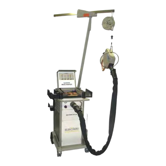
Fig. 10: Multispot system (standard) 4.2 Description The MULTISPOT MI-100 resistance welding unit is designed for special requirements for the repair and production of motor vehicle bodies. The inverter power source is controlled by a micro-processor. After selecting the operating mode, the sheet steel thickness and the welding task, the current and weld time will be assigned automatically. -
Page 20: Display And Control Elements
Resistance Welder MULTISPOT MI-100 Design and functionality 4.3 Display and control elements 4.3.1 On the display and control panel LED “malfunction” → see also 7.2.1 Touch key for selecting welding tool Touch key for selecting welding gun functions Touch key for selecting sheet... -
Page 21: Connections On The Backside
Resistance Welder MULTISPOT MI-100 Design and functionality 4.4.2 Connections on the backside 1 Compressed-air filter unit 2 Coolant-pump air supply 3 Power cord 4 Power switch 5 Coolant outlet towards pump 6 Coolant return Fig. 14: Connections on the backside... -
Page 22: Accessories
Resistance Welder MULTISPOT MI-100 Design and functionality 4.5 Accessories 4.5.1 Scope-of-delivery accessories Water outlet hose (Fig. 16: Water outlet hose) Accessory box (complete with a cutter for dressing electrodes and Allan key for taking off electrode arms/-hoops) ... -
Page 23: Installation
Resistance Welder MULTISPOT MI-100 Installation Installation 5.1 Before installation 5.1.1 Preliminary works Check operating conditions according to specifications. ( See “9”.) If necessary, allow equipment time to adapt to ambient temperature SLOWLY. Make sure that operating company’s supply systems comply with specifications. -
Page 24: Assembling The Balancer
Resistance Welder MULTISPOT MI-100 Installation 5.3 Assembling the balancer Unpack the balancer. Check balancer components for damage. Use the checklist provided (Fig.19) to check whether you have all the parts. Balancer Guide rollers with locking pin and ring ... -
Page 25: Electrical Connections
Resistance Welder MULTISPOT MI-100 Installation 5.4 Electrical connections CAUTION Insufficient conductor cross-sections and fuse protection may make the grid collapse and/or trigger the fuses and make efficient welding impossible. Therefore: Before you connect the welder to the mains, make sure conductor cross-sections are sufficient (at least 6 mm²... -
Page 26: Connecting The Pneumatics
Resistance Welder MULTISPOT MI-100 Installation 5.5 Connecting the pneumatics 1. Take the supply line from the pneumatic grid of the plant and plug it on to the welder (Fig.24). 2. The plant’s pneumatic mains must provide about 8 bar (116 Psi) input pressure to the welder. -
Page 27: Connecting The Pliers
Resistance Welder MULTISPOT MI-100 Installation 5.6 Connecting the pliers 1. Push the main plug of the welding pliers into the main socket of the equipment (Fig.26/1.). 2. Turn the retainer nut clockwise (Fig.26/2.) to lock the connection. Fig.26: Connecting the pliers 3. -
Page 28: Connecting The Welding Gun
Resistance Welder MULTISPOT MI-100 Installation Connecting the welding gun 1. Push the main plug of the welding pliers into the main socket of the equipment (Fig. 28./1). 2. Turn the retainer nut clockwise (Fig. 28/2) to lock the connection 3. Unit will switch automatically and shows the “gun” symbol in the display. -
Page 29: Operation
Resistance Welder MULTISPOT MI-100 Operation Operation 6.1 Preliminary works before welding 6.1.1 Preparing the sheets Always connect the earth connection to the lower sheet. Otherwise the electricity cannot flow. When using insulating layers (e.g. spot welding primer), you must first establish an auxiliary connection (using a vise-grip wrench, for instance) in order to establish the electrical contact. - Page 30 Resistance Welder MULTISPOT MI-100 Operation Exchanging electrode arms 1. To unbolt the electrode arm, use the Allen key provided for that purpose (Fig.30). Fig.30: Unbolting electrode arm 2. Remove the electrode arm simply by pulling it out. (Fig.31). 3. Insert the new electrode arm and bolt down.
-
Page 31: Checks Before Switching On
Resistance Welder MULTISPOT MI-100 Operation Adjusting the distance between Make sure the distance between the electrodes is 6 to 8 mm. electrodes Carry out the first welds, and then check the distance again. Re-adjust, if necessary. Use an Allen key SW5 as gauge in between the tips:... -
Page 32: Switching On
Resistance Welder MULTISPOT MI-100 Operation 6.2 Switching on 1. Once the welder has been installed and prepared according to instructions, you may switch it on by turning the power switch (Fig. 37). Fig. 37: Power switch 6.3 Bedienung über Tastatur LED “malfunction”... -
Page 33: Important Information Concerning Welding
Resistance Welder MULTISPOT MI-100 Operation 6.4 Important information concerning welding Electromagnetic fields DANGER Electromagnetic fields pose a potentially fatal hazard to people with pacemakers or other magnetisable implants. Electromagnetic fields affect the functionality of pacemakers and other magnetisable implants. Electromagnetic fields can irritate human sense organs, nerve and muscle cells. Therefore: ... - Page 34 Resistance Welder MULTISPOT MI-100 Operation Tipping and toppling hazards due to high centre of gravity and obstacles during travel CAUTION ! Tipping and toppling may cause damage to property. This equipment’s centre of gravity is relatively high. In the event the wheels jam and/or block (due to an obstacle or transverse pull, for instance), there is a danger the equipment tips over.
- Page 35 Resistance Welder MULTISPOT MI-100 Operation Adjusting the contact force NOTE! Be sure to set the correct contact force with respect to the current welding because: If the contact force of the electrodes is too high, the electrical resistance will be too weak which, in turn, will affect the welding job.
-
Page 36: Operating The Welding Gun
Resistance Welder MULTISPOT MI-100 Operation 6.5 Operating the welding gun 6.5.1 Push spot welding Caution! Electromagnetic fields! Wear protective goggles and gloves! Electrodes heat up! Flying sparks! Only use the mode "push spot welding" is the area to be welded cannot be reached with the spot welding pliers! 1. -
Page 37: Pulling-Out Dents With Washer
Resistance Welder MULTISPOT MI-100 Operation 6.5.2 Pulling-out dents with washer Grind the damaged area to a bright metal finish. Insert contact piece (Fig. 43) into welding gun. Select "washer" mode and sheet thickness on display. (Sheet steel thickness more than 2 x 1.5 = 3 mm cannot be selected). -
Page 38: High-Speed Planishing Hammer „Sah" (Special Accessory)
Resistance Welder MULTISPOT MI-100 Operation 6.5.3 High-speed planishing hammer „SAH“ (special accessory) Small dents, scratches or hail pitting can easily be removed with the high-speed planishing hammer (42). Grind damaged area to a bright metal finish. Insert high-speed planishing hammer (Fig. -
Page 39: Pushing-In Dents
Resistance Welder MULTISPOT MI-100 Operation 6.5.4 Pushing-in dents Small high spots dents caused by overlapping load in the boot or by beating out with pulling tool can easily be flattened with contact piece (only for sheets up to 1 mm thickness). -
Page 40: Welding-On Threaded Studs
Welding-on threaded studs With the MULTISPOT MI-100 it is possible to weld on threaded studs of 4, 5, 6 mm diameter. Please use the appropriate contact pieces (SB 4 for Ø 4 mm/ SB 5 for Ø 5 mm/SB 6 for Ø 6 mm) Insert appropriate contact piece ) into welding gun. -
Page 41: Welding-On T-Pins
Resistance Welder MULTISPOT MI-100 Operation 6.5.7 Welding-on T-pins For example T-pins used for fixing trim strips, can be welded on using contact pieces TST 3 (1) and TST 5 (7). Incorporated in the tip of the contact piece is a magnet which holds the T-pin during the welding process. -
Page 42: Fixing Sheet Metal Parts (Tacking)
In such cases, the sections can be fixed by tack welding with the MULTISPOT MI-100. Washers from which ¼ has been cut out can be used as fixing aid. Insert contact piece for washers into welding gun to limit stop. -
Page 43: Troubleshooting
Resistance Welder MULTISPOT MI-100 Troubleshooting Troubleshooting 7.1 Health and safety during troubleshooting WARNING People with insufficient skills may suffer injuries. If you carry out troubleshooting and repairs yourself, you may encounter certain risks and hazards that may entail severe injuries. Therefore: ... -
Page 44: Maintenance
Resistance Welder MULTISPOT MI-100 Maintenance Maintenance 8.1 Maintenance schedule Intervals What must be done? WHO should do Visually check the welder and its periphery for damage, dirt, contamination etc. Clean, if necessary ( see “8.2”). Check connections for tight fit. -
Page 45: Cleaning
Resistance Welder MULTISPOT MI-100 Maintenance 8.2.1 Cleaning CAUTION Failure to carry out and/or negligent or improper cleaning jobs may entail damage to property. If you do not clean the welder at all or use aggressive cleaning agents or –methods, there is a danger of damage to property. -
Page 46: Replacing Water Filter
Resistance Welder MULTISPOT MI-100 Maintenance 8.2.3 Replacing water filter Scald hazard DANGER! Scalding may occur due to hot water coming out! While pulling out the cooling water hoses hot water may come out. Therefore: – Wear gloves. – Pull out water hoses carefully. -
Page 47: Empty Cooling Water Tank
Resistance Welder MULTISPOT MI-100 Maintenance 8.2.4 Empty cooling water tank Scald hazard DANGER! Scalding may occur due to hot water coming out! While pulling out the cooling water hoses hot water may come out. Therefore: – Wear gloves. – Pull out water hoses carefully. -
Page 48: Specifications
Resistance Welder MULTISPOT MI-100 Specifications Specifications 9.1 Dimensions and weights Item Value Unit Height 925 / 36 mm / in Width 650 / 26 mm / in Depth 645 / 25 mm /in Weight (w/o accessories) 100 / 220 Kg / lb 9.2 Power requirements... -
Page 49: Exposure Limit Values
Resistance Welder MULTISPOT MI-100 Specifications 9.5 Exposure limit values Welding pliers Item Compliance Exposure limit values accor. EU Safe compliance with directive 2004/40/EC distances ≥ 15 cm perpendicular to pliers opening Safe compliance with distances ≥ 7 cm to welding cable 9.6 Type plates... -
Page 50: Index
Resistance Welder MULTISPOT MI-100 Index 10 Index Accessories............22 Intended purpose ..........7 Adjusting the distance between electrodes ..31 Intended use ............7 Airpuller.............. 42 Inverter control unit ..........20 Ambient conditions ..........48 Appendix ............52 Assembling the balancer ........24 Liability .............. - Page 51 Resistance Welder MULTISPOT MI-100 Index Switching on ............32 T-pins ..............41 Symbols Training Report ...........52 on equipment ..........13 Troubleshooting ..........43 to be installed by operating company ....8 Type plates ............49 Symbols on packaging ........16 Symbols used in the operating manual ....5 washer ..............37...
-
Page 52: Appendix
Resistance Welder MULTISPOT MI-100 Appendix 11 Appendix Training Report NOTE! Master copy. Do not fill in. Make copies. Date Name Type of training Trainer Signature...
Need help?
Do you have a question about the MULTISPOT MI-100 and is the answer not in the manual?
Questions and answers
What is involved in removing the water tank on the welder?