Advertisement

1 • INSTALLATION

• Dimensions and cut-out; panel mounting

48
108 96
92
113
10
96
108 96
92
113
10
Panel mounting:
To fix the unit, insert the brackets provided into the seats on either side of the
case. To mount two or more units side by side, respect the cut-out dimensions
shown in the drawing. To obtain IP65 faceplate protection level, remove the device from
the box, apply the gasket (supplied) with adhesive to the front edge of the box, and then
reinsert the device.
CE MARKING: EMC conformity (electromagnetic compatibility) with EEC Directive
89/336/CEE with reference to the generic Standard EN61000-6-2 (immunity in
industrial environments) and EN50081-1 (emission in residential environments). BT
(low voltage) conformity respecting the Directive 73/23/CEE modified by the Directive
93/68. Limitations: model 1800 conforms to Standard EN55011 for emissions radiated
in industrial environment.
MAINTENANCE: Repairs must be done only by trained and specialized personnel. Cut
power to the device before accessing internal parts.
Do not clean the case with hydrocarbon-based solvents (Petrol, Trichlorethylene, etc.).
Use of these solvents can reduce the mechanical reliability of the device. Use a cloth
dampened in ethyl alcohol or water to clean the external plastic case.
SerVICE: GEFRAN has a service department. The warranty excludes defects caused
by any use not conforming to these instructions.
80080D_MHW_1600-1800_0308_ENG
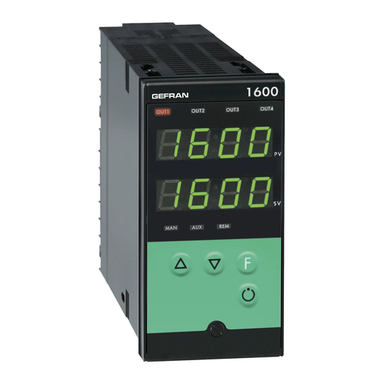
1600 / 1800
CONTROLLER
70
115
44,5
115
115
!
92
For correct and safe
installation, follow the
instructions and observe
the warnings contained in
this manual.
INSTALLATION AND
OPERATION MANUAL
SOFTWARE VERSION 3.2x
code 80080D / Edition 13 - 03/08
2 • TECHNICAL SPECIFICATIONS
Display
Keys
Accuracy
Main input
Thermocouples
Cold junction error
RTD type (scale configurable within indicated
range, with or without decimal point)
PTC type (on request)
Max line resistance for RTD
Safety
°C / °F selection
Linear scale ranges
Controls
pb / dt / di
Action
Cycle time
Main output type
Softstart
Maximum power limit heat / cool
Fault power setting
Automatic blanking
Configurable alarms
Alarm masking
Type of relay contact
Logic output for static relays
(option) remote Setpoint
or Amperometric input
Feedback input
Potentiometer valve position
CT scale range
Transmitter power supply
(optional)
Analogue retransmission signal (opt)
Logic inputs (optional)
Serial interface (optional)
Baud rate
Protocol
Power supply (switching type)
Faceplate protection
Working / Storage temperature range
Relative humidity
Environmental conditions of use

Installation

Weight
EMC conformity has been tested with the following connections
FUNCTION
Power supply cable
Relay output cable
Digital communication wires
C.T. connection cable
TC input
Pt100 input
2 x 4 digits, green, height: 10 and 7 mm (1600V);
20 and 13 mm (1800V)
5 mechanical keys ( ,Man/Aut, INC, DEC, F)
0.2% full scale at 25°C room temperature
TC, RTD (Pt100 - JPT100), PTC,
50mV, Ri ≥ 1MΩ; 10V, Ri ≥ 10KΩ; 20mA, Ri = 50Ω
IEC 584-1 (J, K, R, S, T, B, E, N, Ni-Ni18Mo, L NiCr-CuNi)
0,1° / °C
DIN 43760 (Pt100, JPT100)
990Ω, 25°C
20Ω
detection of short-circuit or opening of probes, LBA
alarm, HB alarm
configurable from faceplate
-1999 to 9999 with configurable decimal point position
PID, Self-tuning, on-off
0.0 ... 999.9% / 0.00 ... 99.99min / 0.00 ... 99.99min
Heat / Cool
on / off, pwm, Open / Close
0.1 ... 200 sec
Relay, Logic, Continuous (optional)
0.0 ... 500.0 min
0.0 ... 100.0 %
-100.0 ... 100.0 %
Optional exclusion, displays PV value
3 configurable alarms type: max, min, symmetrical,
absolute or relative, LBA, HB
- exclusion during warm up
- latching reset from faceplate or external contact
NO (NC), 5A, 250V, cosϕ = 1
11Vdc, Rout = 220Ω (6V/20mA)
0 ... 10V, 2 ... 10V, Ri ≥ 1MΩ
0 ... 20mA, 4 ... 20mA, Ri = 5Ω
Potentiometer > 500Ω,
TA 50mAac, 50/60Hz, Ri = 1,5Ω,
isolation 1500V
configurable from 0, ... , 100.0A
filtered 10 / 24Vdc, max 30mA
short-circuit protection, isolation 1500V
10V / 20mA, isolation 1500V
24V NPN, 4.5mA; 24V PNP, 3.6mA
isolation 1500V
CL; RS422/485; RS232; isolation 1500V
1200 ... 19200
GEFRAN / MODBUS
(std) 100 ... 240Vac/dc ±10%; 50/60Hz, 12VA max
(opt.) 20...27Vac/dc ±10%; 50/60Hz, 12VA max
IP65
0...50°C / -20...70°C
20 ... 85% non-condensing
for internal use only, altitude up to 2000m
Panel, plug-in from front
400g (1600V), 600g (1800V) for the complete version
CABLE TYPE
LENGTH
1 mm
2
1 m
1 mm
2
3,5 m
0,35 mm
2
3,5 m
1,5 mm
2
3,5 m
0,8 mm
2
compensated
5 m
1 mm
2
3 m
1

Advertisement

Table of Contents
loading

Summary of Contents for gefran 1600

  • Page 1 Digital communication wires 0,35 mm 3,5 m C.T. connection cable 1,5 mm 3,5 m SERVICE: GEFRAN has a service department. The warranty excludes defects caused TC input 0,8 mm compensated by any use not conforming to these instructions. Pt100 input...
  • Page 2 0...20mA, 4...20mA, 5Ω, Configurable serial A (Data +) 0...1V, 0...10V,> 1MΩ line isolated to 1500V B (Data -) Potentiometer > 500Ω 1800 1600 RS422/485 or RS232 • Inputs Passive current loop (max. 1200 baud) Available thermocouples: • TC (optional J, K, R, S, T, B, E, N,...
  • Page 3 Device structure: identification of boards SERIAL / W BOARD SERIAL / W BOARD CPU BOARD BOARD POWER BOARD POWER DISPLAY BOARD BOARD DISPLAY BOARD 5 • PROGRAMMING and CONFIGURATION INFO LEVEL 1 MENU Information display Press for approx. dAtA Custom menu Process variable (PV display) 2 sec P.V.
  • Page 4 • InFo Display -999 … 999 Information INFO Manual reset scale points display prot Software protection code Serial (ODE p. r st communication Reset power -100.0 ... 100.0% code 0 No Error Self er. n r 1 Lo diagnostic 2 Hi error updt Software...
  • Page 5 2400 485 / 232 4800 485 / 232 Serial interface SEr.P Serial protocol 9600 485 / 232 ser. p protocol CENCAL, CENCAL GEFRAN 19200 485 / 232 MODBUS MODBUS RTU Parity Parity selection No parity Even • InP Input settings SP.tY...
  • Page 6 Digital filter on aux input filt flt. 2 Digital filter 0.0 ... 20.0 sec (if enabled) 0.0 ... 20.0 sec on main input [see “hrd.1” on Hrd] fild lo. 5 2 Minimum range for aux Digital filter on display Min…max input range 0 ...
  • Page 7 Out W1 an. o . 1 rl. o . 1 Out 1 Assignment of signal or reference value: PV, SP, Allocation of SP-PROG, DEV+, DEV-, IN.AUX, HEAT, COOL, reference signal: AL1, AL2, AL3, serial line value HEAT, COOL, AL1, AL2, AL3, An.o.1, An.o.2 rL.o.1, rL.o.2, rL.o.3, rL.o.4 repetition of...
  • Page 8 • Hrd SEnS Probe type for main input Selection of Thermocouple (TC) Hardware configuration sens probe type for Resistance Thermometer (RTD) main input Thermistor (PTC) hrd.1 Logic Logic Serial Voltage 0...50mV / 10...50mV analogue input 1 input 2 interface Current 0...20mA / 4...20mA Auxiliary input hrd.
  • Page 9 Function of “MAN” LEDs: M/A, L/R, ATUN, IN1, IN2 repetition, led. 1 event programmer, serial port enabled, errors present LEd.1 (MAN), LEd.2 (AUX), LEd.3 (REM) LEd.x Function led. 2 none MAN/AUTO (ON in manual, OFF in auto) LOC/REM (ON in remote, OFF in local) self-tuning enabled autotuning enabled led.
  • Page 10 6 • TIMER + 2 SET POINT, TIMER FUNCTION The timer functionality is enabled in Hrd configuration in hrd.1 parameter setting the code +16 or +48 to activate the selection of two set points. In the case of enabling, parameters _S.S.t. (start/stop timer) and _ _r.t. (reset timer) define the functioning modality. The intervention threshold of the tS timer can be set at level 1 of programming with bottom of scale 9999 sec.
  • Page 11 8 • ALARMS Normal absolute alarm Symmetrical absolute alarm AL1 + [ Hyst1 ] AL2 + Hyst2 AL1 + Hyst1 AL1 - [ Hyst1 ] time time alarm 1 reverse direct alarm 2 For AL1 = reverse absolute alarm (low) with positive Hyst1, AL1 t = 1 For AL1 = symmetrical Lo absolute alarm with Hyst1, AL1 t = 5 (*) = OFF if disabled on power-up For AL1 = symmetrical Hi absolute alarm with Hyst1, AL1 t = 4...
  • Page 12 If the Integral Time value is too long (Weak integral action), deviation between the controlled variable and the setpoint may persist. Contact GEFRAN for more information on control actions. 11 • MANUAL TUNING A) Enter the setpoint at its working value.
  • Page 13 13 • SELF-TUNING The function works for single output systems (heating or cooling). The self-tuning action calculates optimum control parameter values during process startup. The variable (for example, temperature) must be that assumed at zero power (room temperature). The controller supplies maximum power until an intermediate value between starting value and setpoint is reached, after which it zeros power. PID parameters are calculated by measuring overshoot and the time needed to reach peak.
  • Page 14 16 • MAIN INPUT CORRECTION FUNCTION Lets you custom correct reading of the main input by setting four values: A1, B1, A2, B2. This function is enabled by setting “Sens” +8 code (“Hrd” menu). Example: Sens = 1+8 = 9 for RTD probe with input correction. The scale can be reversed if this function is applied to linear scales (50mv, 10V, 20mA, Pot).
  • Page 15 1N4007 diode in parallel with the coil of inductive loads that operate in DC. GEFRAN spa will not be held liable for any injury to persons and/or damage to property deriving from tampering, from any incorrect or erroneous use, or from any use not conforming to the device specifications.
  • Page 16 1600/1800 - 1600P/1800P - 1600V/1800V APPENDIX PONTICELLI PER CONFIGURAZIONE PONTS ÉTAIN POUR CONFIGURATION JUMPERS FOR CONFIGURATION PUENTES PARA CONFIGURACIÓN BRÜCKEN FÜR KONFIGURATION PONTES PARA CONFIGURAÇÃO SCHEDA POWER 90/260 (44995)4 e POWER 10/30 (45115)1 POWER BOARD 90/260 (44995)4 and POWER 10/30 (45115)1...
  • Page 17 S4 - S5 - S6 S5 S6 S22 - S23 - S21 SCHEDA CPU CPU BOARD CPU-KARTE CARTE CPU FICHA CPU PLACA CPU S17 - S20 Fig. 2 DESCRIZIONE PONTICELLI DESCRIPTION JUMPERS BESCHREIBUNG BRÜCKEN Abilitazione configurazione (stagno) S3 (chiuso) Enable configuration (Tin) S3 (closed) Freigabe der Konfiguration (Lötzinn) S3 (geschlossen)
  • Page 18 DESCRIPTION PONTS ÉTAIN DESCRIPCIÓN PUENTES DESCRIÇÃO PONTES Validation configuration (Etanche) S3 (fermée) Habilitación configuración (Estaño) S3 (cerrado) Habilitação da configuração (Estanho) S3 (fechado) Validation configuration (jumper) S14 (fermée) * Habilitación configuración (jumper) S14 (cerrado) * Habilitação da configuração (jumper) S14 (fechado) * Validation étalonnage S4 (fermée) Habilitación calibración...
  • Page 19 INGRESSI DIGITALI (DIP SWITCH S1) DIGITAL INPUTS (DIP SWITCH S1) DIGITALE EINGÄNGE (DIP SWITCH S1) ENTRÉES NUMÉRIQUES (DIP SWITCH S1) ENTRADAS DIGITALES (DIP SWITCH S1) ENTRADAS DIGITAIS (DIP SWITCH S1) INGRESSI / TIPO INPUTS / TYPE EINGÄNGE / TYP ENTRÉES / TYPE ENTRADAS / TIPO ENTRADAS / TIPOS INGRESSO DIGITALE 2...
  • Page 20 SCHEDA OUT SERIALE / OUT W SERIAL OUT BOARD / OUT W SERIELLER AUSGÄNGE / OUT W CARTE OUT SÉRIE / OUT W FICHA OUT SERIE / OUT W PLACA DE COMUNICAÇÃO DIGITAL / OUT W Fig. 3 USCITA ANALOGICA 1 (DIP SWITCHES S2) ANALOGUE OUTPUT 1 (DIP SWITCHES S2) ANALOGER AUSGANG 1 (DIP SWITCHES S2) SORTIE ANALOGIQUE 1 (DIP SWITCHES S2)

This manual is also suitable for:

1800

Table of Contents