Sign In
Upload
Manuals
Brands
gefran Manuals
Controller
SIEIDrive AVy7900
gefran SIEIDrive AVy7900 Manuals
Manuals and User Guides for gefran SIEIDrive AVy7900. We have
1
gefran SIEIDrive AVy7900 manual available for free PDF download: Quick Start Up Manual
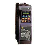
gefran SIEIDrive AVy7900 Quick Start Up Manual (156 pages)
Vector AC Drives
Brand:
gefran
| Category:
Controller
| Size: 2.14 MB
Table of Contents
Table of Contents
3
Safety Symbol Legend
8
Safety Precautions - Precautions de Securité
9
1 Quick Start up Guide
13
Functional Connection Diagram
13
Overview
14
Control Terminals
15
Maximum Cable Cross Section for Regulator Terminals
16
Power Terminals
16
Maximum Cable Cross Section for Power Terminals
16
Encoder Terminals (Xe Connector)
17
Encoder Type Connection
17
Jumpers Setting
18
Maximum Cable Length for Encoder Terminals
18
List of Jumpers and Dip-Switch
19
Keyboard Operation
20
Leds & Buttons
20
Moving Inside a Menu
22
Pre Power Checks
23
Quick Tuning
24
Motor Potentiometer
27
Optional Things
28
Quick Tuning Guide for Factory Configured (or Pre-Configured) Drives
29
Troubleshooting
30
Overflow List
30
List of Self Tune Error Messages
31
Failure Alarms in the Keypad Display
32
Other Faults
34
2 Function and Feature (Overview)
37
3 Inspection Procedure, Component Identification and Standard Specification
39
Upon Delivery Inspection Procedures
39
General
39
Inverter Type Designation
39
Nameplate
40
Component Identification
41
Figure 3.2.2: Drive View & Components
42
Standard Specifications
43
Permissible Environmental Conditions
43
Disposal of the Device
44
AC Input/Output Connection
44
Table 3.3.2.1:AC Input/Output Specifications
45
AC Input Current
46
AC Output
46
Table 3.3.3.1: Nominal Drive Current
47
Open-Loop and Closed-Loop Control Section
48
Accuracy
49
4 Installation Guidelines
51
Mechanical Specification
51
Figure 4.1.3: Drive Dimensions (Sizes 4185 ... 82000)
52
Watts Loss, Heat Dissipation, Internal Fans and Minimum Cabinet Opening Suggested for the Cooling
53
Figure 4.1.5: Keypad Positioning
53
Cooling Fans Power Supply
54
Installation Mounting Clearance
55
Motors and Encoders
56
Motors
56
Encoder
57
Table 4.4.2.2: Encoders Setting Via S11...S23 Jumpers
58
Table 4.4.2.4: Assignment of the High Density XE Connector for a Sinusoidal or a Digital Encoder
60
5 Wiring Procedure
61
Accessing to the Connectors
61
Removing the Covers
61
Figure 5.1.2: Removing the Covers (Sizes 4220 to 82000)
62
Power Section
63
Pv33
63
Figure 5.2.1.3: PV33-3-.. Power Card (Sizes 3110 and 3150)
64
Figure 5.2.1.5: PV33-5-.. Power Card (Sizes 6750 to 71320)
65
Terminal Assignment on Power Section / Cable Cross-Section
66
Regulation Section
67
RV33 Regulation Card
67
Table 5.3.1.3: Jumpers on Regulation Card RV33-3
68
Terminal Assignments on Regulation Section
69
Table 5.3.2.3: Maximum Control Cable Lengths
70
Figure 5.3.1.2: Potentials of the Control Section, Digital I/O NPN Connection
71
Serial Interface
72
Serial Interface Description
72
RS 485 Serial Interface Connector Description
73
Standard Connection Diagram
74
Avy Connections
74
Figure 5.5.1.2: Typical Connection
75
Parallel Connection on the AC (Input) and DC (Intermediate Circuit) Side of Several Inverters
76
Circuit Protection
77
External Fuses of the Power Section
77
External Fuses of the Power Section DC Input Side
78
Internal Fuses
78
Chokes / Filters
79
AC Input Chokes
79
Output Chokes
79
Interference Suppression Filters
80
Table 5.7.2.1: Recommended Values for Output Chokes
80
Braking Units
81
Internal Braking Unit
81
External Braking Resistor
82
Figure 5.8.2.3:Generic Braking Cycle with Triangular Profile
84
Table 5.8.2.2: Braking Thresholds for Different Mains
85
Calculation of Generic External Braking Resistor to be Combined with the Internal Braking Unit with an Approximate Method
86
Buffering the Regulator Supply
87
Avy Power Dip Ride through Data and Restart Setup
89
Table 5.10.1: Drive Trip Times, 230-V Threshold
90
Table 5.10.2: Drive Trip Times, 400-V Threshold
91
Discharge Time of the DC-Link
92
6 Maintenance
93
Care
93
Service
93
Repairs
93
Customer Service
93
Block Diagram Legend
94
7 Block Diagram
95
Avy Inverter Overview
95
Digital Inputs/Outputs & Mapping Standard and Option Cards
96
Analog Inputs/Outputs & Mapping
97
Speed Reference Generation
98
Speed / Torque Regulation
99
Ramp Reference Block
100
Speed Regulator
101
Speed Regulator PI Part
102
Droop Compensation
103
Inertia / Loss Compensation
104
Torque Current Regulator
105
Speed Feedback
106
Motor Control
107
Motor Parameters
108
Sensorless Parameters
109
V/Hz Functions
110
Speed Threshold / Speed Control
111
Speed Adaptive and Speed Zero Logic
112
PID Function
113
Start and Stop Management
114
Power Loss Stop Control
115
Jog Function
116
Motor Potentiometer
117
Multi Speed
118
Dual Motor Setup
119
Brake Unit Function
120
DC Braking Function
121
Dimension Factor / Face Value Factor
122
PAD Parameters
123
Parameters List
127
Emc Directive
154
Advertisement
Advertisement
Related Products
gefran SIEIDrive AVy71100
gefran SIEIDrive AVy71320
gefran SIEIDrive AVy6750
gefran SIEIDrive AVy82000
gefran ADV20 series
gefran SIEIDrive ADV50-1007 Series
gefran SIEIDrive ADV50-1004-XXX-2MF
gefran SIEIDrive ADV50-1007-XXX-4F
gefran SIEIDrive ADV50-3055-2T
gefran SIEIDrive ADV50-1007-XXX-2M-F
gefran Categories
Controller
Control Unit
Relays
Inverter
Measuring Instruments
More gefran Manuals
Login
Sign In
OR
Sign in with Facebook
Sign in with Google
Upload manual
Upload from disk
Upload from URL