Table of Contents
Advertisement
1
2
3
4
80291G_MHW_2500_08-2010_ENG
2500
CONFIGURABLE CONTROLLER
GENERAL INDEX
Page
2
2
2
2
2
3
3
3
4
4
4
5
5
5
6
6
6
6
7
17
20
20
22
23
26
48
48
48
48
49
49
INSTALLATION AND
OPERATION MANUAL
Software version 1.6x
code 80291G / Edition 10 - 08/2010 ITA
Twin setpoint application (Ramp +
Hold + Time expiration alarm)
Heating/Cooling control with
Relative gain
5
6
7
Accessories
RS232/TTL interface for Gefran
Instrument configuration
The contents of each section are summarized
immediately following the section heading
Page
49
50
50
51
51
51
52
53
54
55
56
56
56
56
57
57
57
57
58
65
66
76
1
Advertisement
Table of Contents

Subscribe to Our Youtube Channel
Related Manuals for gefran 2500


Summary of Contents for gefran 2500
-
Page 1: Table Of Contents
Warnings and instructions for Technical-Commercial information mounting to the panel Nominal ambient conditions Order code Electrical connections Accessories Examples RS232/TTL interface for Gefran Functions Instrument configuration Operator interface General operating notes Appendix Navigating through the controller menu Block Diagrams Configuration and programming... -
Page 2: Graphic Symbols Used
• 1 control analog output reliability and applicational flexibility. In particular, this new • 1 power supply probe selectable for strain gauge, line of Gefran temperature controllers is the ideal solution potentiometers and transmitters for application in sectors where performance and service • 4 outputs: OUT1, OUT2, OUT3, OUT4 relay... -
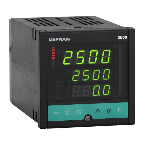
Page 3: Operator Interface
Operator Interface Example: 2500 – 0 – 1 – 0 – 0 – 2 – 1 All the operator interface devices are concentrated on the Model 2500 controller controller faceplate with IP54 level protection. Single main input • 6 buttons to be used for manual regulation / configuration / Digital Input/Outputs 5...8 selection Single continuous control output ±10V (0/4...20mA) -
Page 4: Installation And Connection
This section contains the instructions necessary for connect it up to auxiliary alarm equipment. It is advisable correct installation of the 2500 controllers into the to make sure that alarm signals are also triggered during machine control panel or the host system and for normal operation. -
Page 5: Advice For Correct Installation For Emc
- the voltage between neutral and earth must not be >1V ve loads that operate in Direct Current. - the Ohmic resistance must be < 6Ω; • If the mains voltage fluctuates strongly, use a voltage GEFRAN S.p.A. declines all responsibility for stabilizer. any damage to persons or property caused • In the proximity of high frequency generators or arc wel- by tampering, neglect, improper use or any use ders, use adequate mains filters. -
Page 6: Dimensions And Cut-Out
Example: 2500 – x – x – x – x – x – 1 = 100..240Vac/dc 2500 – x – x – x – x – x – 0 = 20..27Vac/dc... -
Page 7: Electrical Connections
Electrical Connections (Mod. 2500 - 0 - x - x - x - x - x) - 0V power supply 90-260Vac / 18-30Vac/dc + IN4 OUT 1 - 0V c (OUT 1, OUT 2) + IN3 OUT 2 + 24V transmitter supply... - Page 8 Electrical Connections (Mod. 2500 - 0 - x - x - x - x - x) Input IN1 TC - Thermocouple Available thermocouples: J, K, R, S, T (B,E, N, L, U, G, D, C possible by inserting custom linearization)
- Page 9 Electrical Connections (Mod. 2500 - 0 - x - x - x - x - x) IN1 Linear input (I) IN1 potentiometer input Probe power supply 2,5V Linear input in DC 0/4...20mA, Ri = 50Ω Potentiometer R ≥ 100Ω IN1 Linear input (V) Linear input in DC ± 60mV...
- Page 10 Electrical Connections (Mod. 2500 - 1 - x - x - x - x - x) - 0V power supply 90-260Vac / 18-30Vac/dc + IN4 OUT 1 - 0V c (OUT 1, OUT 2) + IN3 OUT 2 + 24V transmitter supply...
- Page 11 Electrical Connections (Mod. 2500 - 1 - x - x - x - x - x) IN2 TC - Thermocouple input IN1 TC - Thermocouple input (*) PT100 for possible compensation of Available thermocouples: remote cold junction J, K, R, S, T...
- Page 12 Electrical Connections (Mod. 2500 - 1 - x - x - x - x - x) IN2 linear input (V) IN1 linear input (V) IN2 PT100 input 2-wire connection 3-wire connection Use wires with adequate section (min 1 mm IN1 PT100 input...
- Page 13 Electrical Connections (Mod. 2500 - 1 - x - x - x - x - x) IN2 Strain-gauge input 4/6 wires Probe power supply 5/10V Green - Exc White + Exc Black or Yellow Blue Brown or Orange IN1 Strain-gauge input 4/6 wires...
- Page 14 Electrical Connections (for all models) IN3, IN4 linear inputs with 3-wire transmitter powered by instrument + 24V Transmitter power supply IN3, IN4 linear inputs with 2-wire transmitter powered by instrument + 24V Transmitter power supply IN3, IN4 linear inputs (I) IN3, IN4 potentiometer inputs Vpot 10Vdc (terminal 5)
- Page 15 Electrical Connections (for all models) Digital inputs DI1, DI2, DI3, DI4 Digital inputs (PNP), 24V, max. 5mA or voltage-free contact (NPN) max. 5mA Single selection PNP/NPN for DI1, DI2, DI3, DI4 by setting configuration parameter (Hd1 = +8) Digital inputs / Digital outputs DI/OUT 5, DI/OUT 6, DI/OUT 7, DI/OUT 8 Digital inputs (PNP) 24V, max.
- Page 16 Electrical Connections (for all models) Retransmission output 0/2...10V, ±10V, max. 25mA protection against short circuit 0/4...20mA, on load max. 500Ω Select type by means of configuration parameter. Serial line - MODBUS RS485 2-wires (standard) RS485 4-wires RS232 Rx + Rx - A (data +) Tx + B (data -) Tx -...
-
Page 17: Examples
Examples The 2500 controller has four typical configurations selectable via the “PASS” parameter, referring to four basic applications. These functions provide quick system start without precluding fine-tuning of parameters 1. SETTING MELT PRESSURE (extruder) Model 2500-0-0-0-0-2-1 PAS = 30 Dialog with PLC or supervision unit (if any) Control output 0...10V... - Page 18 The basic instrument 2500-1-0-x-x-x-x checks the efficiency of the filter upline of the volumetric pump, seen as the difference in input-output pressure. The 2500 instrument acquires the variables via the two main inputs, one of which is also used to control pressure (see application 1). The OUT3 alarm (configurable) signals the need to change the filter (manual or automatic).
- Page 19 (through potentiometer) Drive The basic model 2500-0-x-x-x-x-x with one main input accurately controls roller tension on a winding line. Tension is measured by 2 load cells with 2mV/V sensitivity connected in parallel, powered at 10Vdc by the instrument’s auxiliary power supply.
-
Page 20: Functions
3 • FUNCTIONS This section describes the use and functions of the displays, lighted indicators and buttons making up the 2500 controller operator interface. It therefore contains essential information for correct programming and configuration of the controllers. Operator interface Symbol... - Page 21 Symbol Function Function indicators: with standard configuration, signal the opera- ting state of the controller For configuration, see parameter: LeD. 1 , LeD. 2 , LeD. 3 , LeD. 4 , LeD. 5 on KRD menu MAN/AUTO = ON blinking (manual control) OFF (automatic control) REMOTE SET POINT = ON (IN1 = ON remote Setpoint)
-
Page 22: General Operating Notes
General Notes on Operation Switching on and operating the controller Self-diagnostics • When switched on, the controller runs a self-diagnostics test. During the test, all segments of the display and the 7 lighted indicators flash. • If self-diagnostics detects no errors, the controller enters normal operating state (Level 1) 8888 • Any errors detected by self-diagnostics are stored in a register and can be 8888 displayed with the ERR function on the INF menu. Normal operation Level 1 PV displays the Process Variable value. -
Page 23: Navigating Through The Controller Menu
Navigating the Controller Menus Keep this button pushed to scroll the menus in succession; release when the required menu appears. Push to access the parameters of the selected menu. Keep + pushed to return immediately to level 1. Display level 1 Menu Local Setpoint [LoSP ... - Page 24 Alarm setpoint 1 [Lo. A L ... xi. A L] if absolute [-9999 ... +9999] if relative AL. 1 Alarm setpoint 2 [Lo. A L ... xi. A L] if absolute [-9999 ... +9999] if relative AL. 2 Alarm setpoint 3 [Lo.
- Page 25 Menu Display information Jumper S9 on CPU board S9 ON ? (see section 6 - maintenance) Configuration of control parameters (fG. P d Configuration of function modes Serial Communication Configuration of Input 1 Protection InP. 1 Code Configuration of Input 2 Hardware InP.
-
Page 26: Configuration And Programming
To provide optimum functioning in its intended application, the meter PAS = 99, then pushing 2500 Controller’s control parameters have to be correctly con- After setting the value 99, push and keep pushed figured and programmed. The flexibility and high performance access subsequent menus. - Page 27 Informations This menu lets you display the state of the controller Positioning decimal point Fin.b (read only) dP5. 6 Software release MIN scale limit Fin.A (read only) lo5. 5 MIN scale limit Fin.b Instrument code (read only) lo5. 6 MAX scale limit Fin.A Error code IN 1 (read only) Err.
- Page 28 No. of Pid parameter groups The controller (single loop) can have several selec- [1 ... 8] table PID parameter groups (maximum 8) n. P id Defines the variable used to n.Pid > 1 Setpoint activate the PID parameter Deviation group t.
- Page 29 [(FG. P d] Manual Reset is added to the setpoint value to compen- Manual Reset sate the error at full speed. [-999 ... +999] scale points It is applied in case of P or PD control, and lets the setpoint be reached. It defines the band around the setpoint within which inte- Antireset gral action is active.
- Page 30 Configuration of Operating Modes Digital (from serial line) IN3 absolute Definition of remote set IN4 absolute Fin.A (Math function A) SP. r Fin.b (Math function b) +8 = relative to local setpoint Settable lower limit SP [Scale range of controlled variable] Lo.
- Page 31 Serial Communication This menu lets you configure the various parameters that control serial communication between controller and supervisor. Instrument Identification Code [0 ... 247] Baudrate 1200 bit/s 2400 bit/s 4800 bit/s Select Baudrate 9600 bit/s 19200 bit/s 38400 bit/s 57600 bit/s 115200 bit/s Parity Select Parity...
- Page 32 In P. 1 Setting Input 1 This menu lets you configure parameters for the input 1 signals Probe type, signal, enable custom linearization, and main input scale. InP. 1 Probe type Scale limits Probe type Scale limits 13 Potentiometer ≥100Ω -19999/99999 Input disabled with 2.5V power supply TC J °C...
- Page 33 In P. 2 Setting Input 2 This menu lets you configure parameters for the input 2 signals Probe type, signal, enable custom linearization, and main input scale. InP. 2 Probe type Scale limits Probe type Scale limits 13 Potentiometer ≥100Ω -19999/99999 Input disabled with 2.5V power supply TC J °C...
- Page 34 In P. 3 Setting Input 3 This menu lets you configure parameters for the input 3 signals. InP. 3 Probe type Scale limits Input disabled 0...10V -19999/99999 Probe type, signal, enable custom 0...20mA -19999/99999 linearization, and main input scale tyP. 3 4...20mA -19999/99999 potentiometer...
- Page 35 In P. 4 Setting Input 4 This menu lets you configure parameters for the input 4 signals. InP. 4 Probe type Scale limits Input disabled 0...10V -19999/99999 Probe type, signal, enable custom 0...20mA -19999/99999 linearization, and main input scale tyP. 4 4...20mA -19999/99999 potentiometer...
- Page 36 ALL Setting Alarms This menu lets you configure parameters for the alarm functions. Reference quantity n. alarm Fin.A (math function A) n = 1 Fin.b (math function b) PV - Process Variable (input selected in SPU) Select reference quantities SSP - Active Setpoint Alarm n SP - Local Setpoint DEV - Deviation (PV - SSP) (only for absolute type)
- Page 37 [ALL] MIN limit alarm setpoint [-19999 ... 99999] Lo. A L MAX limit alarm setpoint [-19999 ... 99999] xi. A L Alarm 1 Alarm 2 Alarm 3 Fault Action (definition of alarm state in case of broken probe Err, Sbr, Ebr) Active only for the alarm related to the fault input State of alarms 4...10 = OFF...
- Page 38 Setting Outputs 0 v t This menu lets you configure the output parameters. OUT 1 Attribute reference signal RL. 1 OUT 1 Cycle Time (for function CO1 or CO2 only) [1 ... 200] sec. ct. 1 Function OUT 2 AL1 – alarm 1 Attribute reference signal RL.
- Page 39 Function [0vt] AL1 – alarm 1 AL2 – alarm 2 AL3 – alarm 3 LBA – alarm LBA OUT 5 Repeat logic input 1 Attribute reference signal RL. 5 Repeat logic input 2 Repeat but 1 key AL1 or AL2 AL1 or AL2 or AL3 OUT 6 AL1 and AL2...
- Page 40 Protection Code P R O This menu lets you enable/disable the display and/or change of certain parameters. (To access this menu, see the section “Using the controller menus”) Display Change SEt. P , SP. 1 , SP. 2 , In. 1 , In. 2 SEt.
- Page 41 [xrd] Select Offset CO1 t0F. 1 (0.0 ... 100.0%) (0.0 ... 100.0%) Fin.A (0.0 ... 100.0%) Select Offset CO2 t0F. 2 +4: 0.0 ... -100.0% +8: -100.0 ... +100.0% Function disabled Fin.A = ( ((C1.A * In1.A)^ C2.A) OPEr.A ((C3.A * In2.A)^ C4.A)) / C5.A Maths function A IN1 + IN2 Fvnc.
- Page 42 [xrd] Function disabled Fin.b = ( ((C1.B * In1.B)^ C2.B) OPEr.B ((C3.B * In2.B)^ C4.B)) / C5.B IN1 + IN2 IN1 - IN2 Maths function B IN1 / IN2 [IN2 only positive scales (1 ...99999)] Fvnc. b Square root IN1 [IN1 only positive scales (0 ...99999)] (IN1 + IN2)/ 2 if Func.b = 1 IN3 * C1.B...
- Page 43 [xrd] 0 IN1 1 IN2 2 IN3 Select controlled variable 3 IN4 4 Fin.A 5 Fin.b Number of Alarms Enabled [0 ... 10] AL. n Function Disabled (no function) Setpoint LOC / REM HOLD IN1 Peak Key Function Reset memory latch bvt.
- Page 44 Function [xrd] Disabled (no function) Setpoint LOC / REM HOLD IN1 Reset alarm latch Digital input 1 function Selection SP1 / SP2 diG. 1 Start / Stop Self Tuning Start / Stop Auto Tuning Set / Reset outputs OUT 1 ... OUT 4 (for diG.
- Page 45 [xrd] No function MAN / AUTO controller LED 1 Function LOC / REM HOLD IN1 LEd. 1 HOLD IN2 Self Tuning on Auto Tuning on LED 2 Function Repeat logic input 1 Repeat logic input 2 LEd. 2 Error (broken probe) Softstart running Indicate SP1 / SP2 LED 3 Function...
- Page 46 Input Linearization L ’ N This menu lets you run custom linearization. Variable intervals (max 32) Variable intervals (max 32) L ’ N self-learning from IN1 Variable intervals (max 32) self-learning from IN2 Linearization type Variable intervals (max 32) [0 ... 5] self-learning from IN3 TyP.L Variable intervals (max 32)
- Page 47 U. ( A is run maximum calibration U. ( A phase 1 (Least Significant Word) Potx. L maximum calibration phase 2 (Most Significant Word) Potx. x U. ( A Note.: only for model with a single input: 2500-0-... 80291G_MHW_2500_08-2010_ENG...
-
Page 48: Application Notes
Application Notes HOLD Function The input value and alarms are frozen while the logic input is closed. With logic input closed, a reset turns OFF both the relay outputs and the alarms latch. Alarms Normal absolute alarm Symmetrical absolute alarm AL1 + [ Hy1* ] AL2 + Hy2 AL1 + Hy1... -
Page 49: Manual Tuning
If the Integral Time value is too long (Weak integral action), deviation between the controlled variable and the setpoint may persist. Contact GEFRAN for more information on control actions. Manual Tuning A) Enter the setpoint at its working value. -
Page 50: Software On/Off Switching Function
Software ON/OFF switching function How to switch the unit OFF: hold down the “F” and “Raise” keys simultaneously for 5 seconds to deactivate the unit, which will go to the OFF state while keeping the line supply connected and keeping the process value displayed. The SV display is OFF and “OFF”... -
Page 51: Auto-Tuning
Auto-Tuning Enabling the auto-tuning function blocks the PID parameter settings. It can be one of two types: permanent (continuous) or single-action (one-shot). * Continuous auto-tuning is activated via the Stu parameter (values 1, 3, 5). It continuously reads system oscillations, immediately seeking the PID parameter values that reduce the current oscillation. It does not engage if the oscillations drop below 1.0% of the proportional band. -
Page 52: String Assigned To An Alarm
String assigned to an alarm Each enabled alarm can be assigned an alphanumeric string composed of 5 characters, to be displayed on the PV, SV or F in level 1. The string of alarm n (with n from 1 to 10) is enabled by means of parameter At.n = +512 (to display the string when the alarm trips) or At.n = +1024 (to display the string when the alarm limit is exceeded in case of alarm with time delay). -
Page 53: Maths Functions
Example: to display the strings corresponding to alarms 1, 2, 4 on display SV and 3, 5 on display F, you have to set: = 1 + 2 + 8 = 11 Sdss. P = 4 + 16 = 20 Sds. -
Page 54: Ratio Controller
RATIO CONTROLLER Settings Level 1 display of ratio calculation starting with vers. 1.14 Set the following parameters: “CFG” menu parameter SP.r = 4 (5) math function A (B) “CFG” menu parameter M.A.t = 0 mandatory function mode “Hrd” menu parameter Func.A = 7 (IN3 * C1.A) “InP.3”... -
Page 55: Technical Specifications
5 • TECHNICAL SPECIFICATIONS This section contains a list of the Technical Specifications for the 2500 Controller. Display 1 x 5 red/green bicolor digits, height 13mm 2 x 5 red digits, height 10mm 2 x red bargraph, 10/20 led 5 x led red... -
Page 56: Maintenance
Sections 2 with soft bristles. and 4 of these Instructions for use, the 2500 Controller will work Repairs normally without any need for maintenance, apart from the usual... -
Page 57: Troubleshooting Guide
2500 – x – x – x – x – x – 1 = 100..240Vac/dc 2500 – x – x – x – x – x – 0 = 20..27Vac/dc The characters shown on the Possible fault with one of the display segments. -
Page 58: Appendix
APPENDIX Display Default CONF Description Menu MAIN PU / SU / F Local Setpoint Set. P Setpoint 1 SP. 1 Setpoint 2 SP. 2 Input IN1 main In. 1 Input IN2 main In. 2 Input IN3 auxiliary In. 3 Input IN4 auxiliary In. - Page 59 Display Default CONF Description 100.0 Proportional band, group 4 Pb. 4 Integral time, group 4 It. 4 Derivative time, group 4 dt. 4 Reset power, group 4 PrS. 4 Activation setpoint group 4 UAL. 4 100.0 Proportional band, group 5 Pb.
- Page 60 Display Default CONF Description Digital filter input IN2 Fit. 2 Decimal point position for IN2 dPS. 2 Min. scale limit input IN2 LoS. 2 1000 Max. scale limit input IN2 xiS. 2 Offset input IN2 0fS. 2 0.000 Offset input IN2 calibrated 40mV SG0F.
- Page 61 Display Default CONF Description Activation time alarm 5 rA. 5 Time base for activation time alarm 5 bt. 5 Character A alarm string 5 Sda. 5 Character B alarm string 5 SdB. 5 Character C alarm string 5 Sd(. 5 Character D alarm string 5 SdD.
- Page 62 Display Default CONF Description Output reference OUT3 rL. 3 Cycle time for output OUT3 (t. 3 Output reference OUT4 rL. 4 Cycle time for output OUT4 (t. 4 Output reference OUT5 rL. 5 Output reference OUT6 rL. 6 Output reference OUT7 rL.
- Page 63 S. 0 7 b (S. 1 4) Segment 7 linearized value (Step 14) S. 0 8 A (S. 1 5) 2500 Segment 8 input value [1/10.000] f.s. (Step 15) S. 0 8 b (S. 1 6) Segment 8 linearized value (Step 16) S.
- Page 64 S. 2 8 b (S. 5 6) Segment 28 linearized value (Step 56) S. 2 9 A (S. 5 7) 9063 Segment 29 input value [1/10.000] f.s. (Step 57) S. 2 9 b (S. 5 8) Segment 29 linearized value (Step 58) S.
-
Page 65: Block Diagrams
Block Diagrams 80291G_MHW_2500_08-2010_ENG... -
Page 66: Functional Diagram
80291G_MHW_2500_08-2010_ENG... - Page 67 80291G_MHW_2500_08-2010_ENG...
- Page 68 80291G_MHW_2500_08-2010_ENG...
- Page 69 80291G_MHW_2500_08-2010_ENG...
- Page 70 80291G_MHW_2500_08-2010_ENG...
- Page 71 80291G_MHW_2500_08-2010_ENG...
- Page 72 80291G_MHW_2500_08-2010_ENG...
- Page 73 80291G_MHW_2500_08-2010_ENG...
- Page 74 80291G_MHW_2500_08-2010_ENG...
- Page 75 80291G_MHW_2500_08-2010_ENG...
-
Page 76: Examples Of Custom Linearization
EXAMPLES OF CUSTOM LINEARIZATION Example of custom linearization: type 0 (at variable amplitude intervals, max. 32) For positive polarization signals (ex. 0...50mV) S. 0 0 is the value displayed for minimum input (ex. 0mV); if 32 intervals are set, S. 3 2b is the value displayed for input = S. 3 2A * (f.s. / 10000) (ex. - Page 77 Gefran 2500 Process Controller: Installation and Operation Manual Tel: +27 11 966 9800 (JHB) +27 21 762 8995 (CT) sales@thermon.co.za www.unitemp.com/contact...
Need help?
Do you have a question about the 2500 and is the answer not in the manual?
Questions and answers