Table of Contents
Advertisement
Quick Links
Advertisement
Table of Contents

Subscribe to Our Youtube Channel
Summary of Contents for IDTECK Star FINGER006
- Page 1 Quick Installation Guide Fingerprint Identification Proximity / PIN Reader...
-
Page 2: Important Safety Instruction
If the product exhibits a distinct change in performance. 2. WHAT’S INCLUDED Please unpack and check the contents of the box. If any of these parts are missing, please contact a nearby distributor or IDTECK. -
Page 3: Front Panel
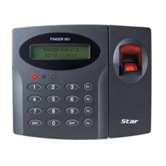
※ FINGER006 SERIES QUICK INSTALLATION GUIDE 3. PARTS CODE AND DESCRIPTION * As long as there is not mention, contents below are applied to FINGER006, IP-FINGER006, FINGER006SR equally. 3.1 Front Panel LCD Display Fingerprint Scanner 3 LED Indicators (showing system status) 16 Numeric Keypad Function Keypad LCD Display... - Page 4 Switch Temper Switch Initialization Switch This switch is used to initialize Star FINGER006. For initialization, press down this switch and then keep it more than 2 seconds. Refer to ‘8.2 System Initialization’ for more details. Communication Display LED # 3, 4(yellow, green) LED will twinkle during RS232, RS422 and TCP/IP communication.
- Page 5 ※ FINGER006 SERIES QUICK INSTALLATION GUIDE 3.3 Connection and Color Code Table I/O PORT NAME SIGNAL NAME COLOR CODED POWER (CON7) Main Power(+12V) DC +12V Power Ground Black OUTPUT (CON4) Not in Use Gray with Red Stripe Not in Use Blue with White Stripe Not in Use White with Red Stripe...
- Page 6 ※ FINGER006 SERIES QUICK INSTALLATION GUIDE RS422-TX(-) TX(-) Yellow RS422-TX(+) TX(+) Gray RS422-RX(-) RX(-) Blue RS422-RX(+) RX(+) Brown TCP/IP Communication (CON6) TCP/IP Communication 8PIN connector module (Optional) 3.4 TCP/IP Module (Option) The Finger006 is able to use TCP/IP Communication. An optional TCP/IP module is needed for TCP/IP communication to the PC.
-
Page 7: Installation Tips & Check Point
* As long as there is not mention, contents below are applied to FINGER006, IP-FINGER006, FINGER006SR equally. Installing the Star FINGER006/ iPASS IP-FINGER006 / IDTECK FINGER006SR is an easy task. It can be installed with common hand tools and readily available communications wires. -
Page 8: Check Point During Installation
※ FINGER006 SERIES QUICK INSTALLATION GUIDE Belden #9512, 22 AWG Reader (Power and Data) 4 conductor, shielded ② FINGER006 Controller Belden #9514, 22 AWG 8 conductor, shielded Belden #9512, 22 AWG Door Contact Exit Button 4 conductor, shielded ③ Sensor Input Belden #9514, 22 AWG Input Controller... - Page 9 ※ FINGER006 SERIES QUICK INSTALLATION GUIDE 4.2.2 How to Connect Termination Resistors Figure: Termination Resistors for 2-Wire RS485 Communication System RS422/RS232 Figure: Termination Resistors for 4-Wire RS422 Communication System 4.2.3 Grounding System for Communication Cable We recommend using proper grounding system on the communication cable. The best method for grounding system is to put the shield wire of the communication cable to the 1 class earth grounding;...
-
Page 10: Installation Of The Product
※ Caution Before mounting the Star FINGER006 / iPASS IP-FINGER006 / IDTECK FINGER006SR unit to the Wall Mount bracket, an operational test of the unit should be completed, because the locking pins will lock the unit to the Wall Mount. -
Page 11: System Initialization
※ FINGER006 SERIES QUICK INSTALLATION GUIDE 5.2 System Initialization You have to initialize the FINGER006 unit prior to first installation. Once power is supplied to the FINGER006, press the initialization switch in the back of the FINGER006 for more than 2 seconds. If you want initialization, press key <1> otherwise press key <0>. SYSTEM INIT. -
Page 12: Rs232 Communication Port Connection
※ FINGER006 SERIES QUICK INSTALLATION GUIDE Control Signal Connection - Connect input wire of the controller to Error Signal Out wire (Blue with Red Stripe). - Connect input wire of the controller to OK Signal Out wire (Green with Red Stripe). - Connect output wire of the controller to Error Signal In wire (Green with White stripe). - Page 13 ※ FINGER006 SERIES QUICK INSTALLATION GUIDE Figure: RS422 Communication between FINGER006 and the PC 6.2.2 RS422 Connection (Multiple FINGER006 Connections) RS422/RS232 converter is required to use RS422 communication between multiple FINGER006 units and a host PC. Please follow the next instructions. First, you have to connect all RS422 port of all FINGER006s in parallel.
-
Page 14: Basic Setting
※ FINGER006 SERIES QUICK INSTALLATION GUIDE 6.3 TCP/IP Converter (External Version) When you use the TCP/IP converter, choose only one converter between RS232 and RS422. Figure: TCP/IP Converter between FINGER006s and the Host PC INTERFACE FINGER006 ILAN422 LINE COLOR TX (CON2) RX (RS232 DSUB9) BLACK+WHITE RS232... -
Page 15: Time Setting
※ FINGER006 SERIES QUICK INSTALLATION GUIDE 7.2 How to Enter the Setup Menu For a setup or FINGER006 setting adjustment, you have to enter the SETUP MENU, first. To do so, press the <0> key 8 times for Master ID (Default “00000000”) and the user can get into the SETUP MENU. There are 4 main SETUP MENUs and you first get into [SETUP MENU F1]. -
Page 16: Normal Operation
※ FINGER006 SERIES QUICK INSTALLATION GUIDE 8. Operation * As long as there is not mention, contents below are applied to FINGER006, IP-FINGER006, FINGER006SR equally. 8.1 Normal Operation Power On When the power is applied to FINGER006, the “RED LED” is turned on. Fingerprint Identification 1. - Page 17 ※ FINGER006 SERIES QUICK INSTALLATION GUIDE 9. Template...


Need help?
Do you have a question about the Star FINGER006 and is the answer not in the manual?
Questions and answers