IDTECK LX505 User Manual
Proximity / pin access controller
Hide thumbs
Also See for LX505:
- User manual (72 pages) ,
- User manual (90 pages) ,
- User manual (78 pages)

Subscribe to Our Youtube Channel
Related Manuals for IDTECK LX505


Summary of Contents for IDTECK LX505
- Page 1 All manuals and user guides at all-guides.com User’s Manual Proximity / PIN Access Controller...
-
Page 2: Table Of Contents
)......26 OMMUNICATION ONNECTION PTIONAL 9.4 S ..........27 ERIAL RINTER ONNECTION 10. BASIC SETTING............28 10.1 I LX505 ..........28 NITIALIZATION OF 10.2 H SETUP MENU ......... 29 OW TO NTER THE 10.3 L ............ 29 ANGUAGE ETTING 10.4 D .......... - Page 3 All manuals and user guides at all-guides.com 11.1 N ............ 33 ORMAL PERATION 11.2 D ............ 33 EFAULT ETTING 12. SETTING CHANGES............. 34 12.1 F1 SETUP MENU ............ 35 12.1.1 Language ........................... 36 12.1.2 Date and Time Setting ....................... 36 12.1.3 Reader #1 Mode ........................
- Page 4 All manuals and user guides at all-guides.com 12.6.8 Output Setting for Reader#2 ID OK Level 1 ..............59 12.6.9 Output Setting for Reader#2 ID OK Level 2 ..............59 12.6.10 Output Setting for Reader#2 ID OK Level 3 ..............59 12.6.11 Output Setting for Reader#2 ID OK Level 4 ..............
-
Page 5: Important Safety Instructions
All manuals and user guides at all-guides.com 1. คํ า แนะนํ า สํ า หรั บ ความปลอดภั ย เพื ่ อ ความปลอดภั ย ในการใช ง าน Proximity / PIN Access Controller, you are กรุ ณ าศึ ก ษาข อ มู ล คํ า แนะนํ า สํ า หรั บ ความปลอดภั ย ด า นล า ง recommended ทํ... -
Page 6: General
All manuals and user guides at all-guides.com 2. General ถู ก ออกแบบให ใ ช ส ํ า หรั บ ควบคุ ม ประตู และ เวลาเข า ออกของพนั ก งาน IDTECK LX505 / LX505SR มี IDTECK LX505 / LX505SR 4 input ports, 2 Form-C relay ติ... -
Page 7: Specification
• user serial communication • Door Phone Function (Optional) • Compatible Software : STARWATCH TIME PRO, LX ACCESS PRO II • 13,56MHz Contactless SMART Card Access Controller(LX505SR) 4. Specification Model LX505 และ 8bit 16bit Microprocessor Program Memory 256KByte ROM Memory... - Page 8 All manuals and user guides at all-guides.com IDA150 / IDA200 Active Type compatible ระยะเวลาในการอ า น บั ต ร 30ms Power / Current DC 12V / Max.650mA LX505: Port (26bit Wiegand, 4 / 8bit Burst สํ า หรั บ สํ า หรั บ PIN) Anti-Pass Back...
-
Page 9: Identifying Supplied Parts
All manuals and user guides at all-guides.com Beeper Piezo Buzzer ถึ ง ถึ ง 0° +50°C (+32° +122°F) ถึ ง ถึ ง -15° +70°C (+5° อุ ณ หภู ม ิ ใ นการใช ง าน Controller +158°F) ถึ ง ถึ ง -35°... -
Page 10: Product Overview
6. Product Overview 6.1 Features การทํ า งานแบบ Standalone ประกอบด ว ย สํ า หรั บ ควบคุ ม IDTECK LX505 / LX505SR external reader ( ประตู จะอ า นหมายเลขบั ต ร และ ทํ า การตรวจสอบว า มี ) . access controller สิ... - Page 11 All manuals and user guides at all-guides.com การตั ้ ง ค า Holiday Schedule ยกเว น วั น อาทิ ต ย คุ ณ สามารถกํ า หนดวั น หยุ ด ได ใน holidays holiday แต ล ะ จะ กั บ schedule. holiday schedule linked...
- Page 12 จะส ง สั ญ ญาณไปยั ง อื ่ น ๆ ที ่ IDTECK LX505 / LX505SR security devices เชื ่ อ มต อ อยู Two Men Operation การทํ า งานนี ้ จะเป น การให อนุ ญ าตให...
-
Page 13: Product Explanation
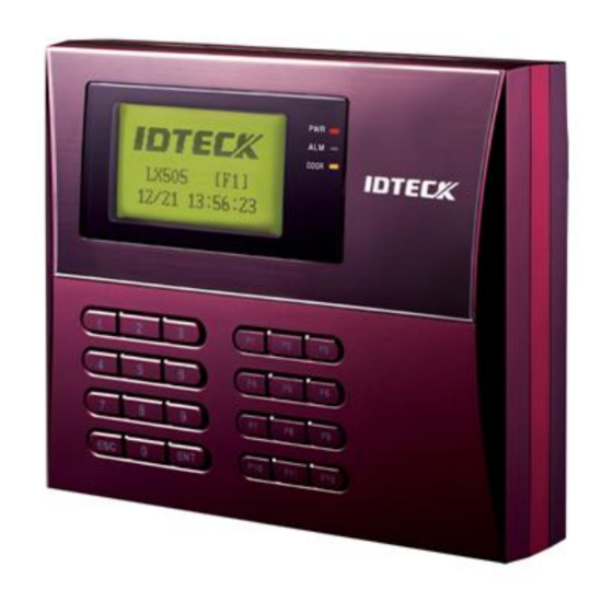
สั ญ ญาณไฟ แสดงสถานะของการทํ า งาน ปุ ม กด ปุ ม รวม ปุ ม function) Figure: Description of LX505 Front Panel หน า จอแสดงผล หน า จอ แสดงสถานะของ • LX505. สั ญ ญาณไฟ แสดงสถานะของการทํ า งาน •... -
Page 14: Color Coded & Wring Table
All manuals and user guides at all-guides.com Figure: Connector Layout 6.2.3 Color Coded & Wring Table SIGNAL NAME WIRE COLOR I/O PORT NAME CON-1(2PIN CONNECTOR) แดง DC 12V Main Power (+12V) ดํ า Power Ground GND (-) CON-2 (3PIN CONNECTOR : Serial Printer) ชมพู... -
Page 15: Installation Tips & Check Point
All manuals and user guides at all-guides.com ส ม สลั บ ดํ า DP_GND น้ ํ า เงิ น DATA-0 DP_D0 น้ ํ า ตาล DP_D1 DATA-1 CON-7: TCP/IP RJ45 CONNECTOR 7. Installation Tips & Check Point 7.1 Check Points before Installation 7.1.1 Selection of Cable รู... -
Page 16: Recommended Cable Type And Permissible Length
8 conductor, shielded Belden #9512, 22 AWG Door Contact 4 conductor, Exit Button shielded 300m Sensor Input Belden #9514, Input -> LX505 22 AWG 8 conductor, shielded Door Lock, Belden #9409, Alarm Device 18AWG 300m Lock (Alarm) -> 2 conductor,... -
Page 17: How To Connect Termination Resistors
All manuals and user guides at all-guides.com system. ตั ว อย า งเช น ถ า คุ ณ ใช และสาย ยาว เมตร อั ต รา 9,600 baud rate cable 1,200 ความเร็ ว ในการส ง สั ญ ญาณจะเท า กั บ ความเร็... -
Page 18: Reverse Diode Connection
แต ถ า ทํ า การเชื ่ อ มต อ กั บ ไม ถ ึ ง พื ้ น ดิ น และลอยสู ง จากระดั บ พื ้ น ดิ น LX505) chassis ground จะทํ า ให ก ารส ง สั ญ ญาณเกิ ด ป ญ หาได... -
Page 19: Installation Of Product
“Initialize OK? 1:Yes 0:No”. <1> ต อ งการ ระบบ หลั ง จากที ่ ข ั ้ น ตอน เสร็ จ สิ ้ น ระบบจะ initialize initialization ทํ า การเข า สู และหน า จอจะแสดง normal mode “IDTECK, LX505 [F1], Date Time”. -
Page 20: Wall Mount Installation
All manuals and user guides at all-guides.com Press and hold the Power ON initialization button. Put the +12V DC power to the LX505. Release the button when the Initialize OK? LCD displays “Initialize OK?” 1: Yes 0: No <1> KEY? “SYSTEM... - Page 21 All manuals and user guides at all-guides.com ใช ง าน สายสี เ ขี ย ว สายสี เ ขี ย วสลั บ ขาว Aux Input #1( ), Aux Input #2( เชื ่ อ มต อ สายหนึ ่ ง เส น จาก เข...
-
Page 22: Output Connection
All manuals and user guides at all-guides.com เชื ่ อ มต อ กั บ 8.4.3 Output Door Lock (Power Fail Safe) Connection (Door Relay) เชื ่ อ มต อ จาก สายสี เ ทาสลั บ แดง กั บ COM wire Door Relay ( +12V. -
Page 23: External Reader Connection
เชื ่ อ มต อ จาก กั บ สายสี ฟ า Data-1 wire Proximity Reader • Compatible Readers (External Reader): LX505: Standard 26bit Wiegand Format Proximity Readers และ Standard 26bit Wiegand + 8bit Burst Format Proximity keypad Reader LX505SR: Standard 34bit Wiegand Format Proximity Reader และ... -
Page 24: Communication
กั บ ของ 9-pin female connector COM Port host PC. และ Install run the LX505 Application Software. Figure: RS232 Communication 9.2 RS485 Communication Port Connection 9.2.1 RS485 Connection (Standalone Unit) ต อ งใช ในการเชื ่ อ มต อ แบบ RS485/RS232... -
Page 25: Rs485 Connection (Multiple Units)
9-pin connector (RS232) converter ของ Port host PC. และ Install run the LX505 Application Software. Figure: RS485 Connection between the LX505 and a Host PC 9.2.2 RS485 Connection (Multiple Units) ต อ งใช ในการเชื ่ อ มต อ แบบ RS485/RS232 converter RS485 ระหว... -
Page 26: Tcp/Ip Communication Port Connection (Optional)
ของ port host PC. และ Install run the LX505 application software. Figure: RS485 Communication between Multiple LX505 Units and a PC 9.3 TCP/IP Communication Port Connection (Optional) ต อ งใช ในการเชื ่ อ มต อ แบบ กั บ TCP/IP Module TCP/IP communication host PC. -
Page 27: Serial Printer Connection
All manuals and user guides at all-guides.com Figure: TCP/IP Communication between Multiple LX505 units and a host PC เชื ่ อ มต อ กั บ Serial Printer 9-pin connector (Serial communication connector, female) ใช ในการเชื ่ อ มต อ กั บ... -
Page 28: Basic Setting
All manuals and user guides at all-guides.com Figure: RS232 Communication between LX505 and a Serial Printer 10. Basic Setting 10.1 Initialization of LX505 หลั ง จากทํ า การติ ด ตั ้ ง และเชื ่ อ มต อ เสร็ จ เรี ย บร อ ยแล ว... -
Page 29: How To Enter The Setup Menu
SUBMENU <4> <6>. วิ น าที หรื อ คุ ณ กดปุ ม จะออกจาก และกลั บ สู โ หมดการทํ า งาน <ESC>, LX505 SETUP MENU ปกติ โดยคุ ณ สามารถเปลี ่ ย น ได ท ี ่ Master ID [F7 SETUP MENU]. -
Page 30: Date / Time Setting
รหั ส คื อ สํ า หรั บ วั น อาทิ ต ย สํ า หรั บ วั น จั น ทร LX505 24-hour. สํ า หรั บ วั น อั ง คาร สํ า หรั บ วั น พุ ธ... - Page 31 All manuals and user guides at all-guides.com ลงทะเบี ย นโดยการป อ น ในกรณี ท ี ่ ป อ นข อ มู ล ผิ ด พลาดระหว า งการลงทะเบี ย น คุ ณ สามารถกดปุ ม เพื ่ อ ทํ า การลบข อ มู ล NOTE| ที...
- Page 32 แล ว พยายามที ่ จ ะออกโดยผ า นทาง Reader#1) Reader#2 (Exit Reader) จะแสดงข อ ความผิ ด พลาด ที ่ ห น า จอ LX505 (“Access Door Error”) LCD. หมายถึ ง เป น ค า ส ว น และ ใช ส ํ า หรั บ...
-
Page 33: Operations
เป ด เครื ่ อ ง เมื ่ อ ทํ า การเป ด เครื ่ อ ง ไฟสี แ ดงจะสว า ง LX505, การอ า นบั ต รที ่ ล งทะเบี ย น เมื ่ อ บั ต รที ่ ล งทะเบี ย นแล ว... -
Page 34: Setting Changes
SUBMENU <4> <6>. วิ น าที หรื อ คุ ณ กดปุ ม จะออกจาก และกลั บ สู โ หมดการทํ า งาน <ESC>, LX505 SETUP MENU ปกติ โดยคุ ณ สามารถเปลี ่ ย น ได ท ี ่ Master ID [F7 SETUP MENU]. -
Page 35: F1 Setup Menu
All manuals and user guides at all-guides.com 12.1 F1 SETUP MENU ENGLISH (DEFAULT) LANGUAGE ESPANOL Basic Languages PORTUGUESE KOREAN <4> or <6> KEY CHINESE Optional Languages JAPANESE ARABIC SET DATE/TIME Enter 15 digits for date and time <4> or <6> KEY ID ONLY(DEFAULT) READER#1 MODE ID+P/W... -
Page 36: Date And Time Setting
All manuals and user guides at all-guides.com ภาษา 12.1.1 ค า คื อ ภาษาอั ง กฤษ default ภาษาที ่ ร องรั บ ภาษาอั ง กฤษ, สเปน และ โปรตุ เ กส ตั ้ ง ค า วั น ที ่ แ ละเวลา 12.1.2 e.g. -
Page 37: Reader#2 Mode
READER#1 MODE. หมายถึ ง ที ่ ต อ เชื ่ อ มกั บ NOTE: READER#2 Exit Reader LX505. ใช ง าน นี ้ ถ า ต อ งการทํ า งานโดยไม ม ี ID ONLY: mode password ใช ง าน... -
Page 38: Baud Rate Setting
ให ท ํ า ดั ง นี ้ ตรวจสอบหมายเลขเครื ่ อ ง และ ใน LX505 host PC Software. ตรวจสอบ และ ใน Baud Rate LX505 host PC Software. ตรวจสอบ และ สาย COM port cable. ตรวจสอบ ของ COM port settings host PC... -
Page 39: F2 Setup Menu
All manuals and user guides at all-guides.com 12.2 F2 SETUP MENU EVENT MEMORY USE(DEFAULT) NOT USE <4> or <6> KEY ID DISPLAY MESSAGE(DEFAULT) ID+MESSAGE <4> or <6> KEY TIME UNIT UNIT: 1 SEC (DEFAULT) UNIT: 0.1 SEC <4> or <6> KEY OUTPUT T/S+ID NOT USE(DEFAULT) <4>... -
Page 40: Event Memory
เต็ ม ถ า คุ ณ เลื อ ก event memory USE, LX505 จะเก็ บ รั ก ษา ทั ้ ง หมดไว ใ นหน ว ยความจํ า แต ถ า คุ ณ เลื อ ก event transactions ข อ มู ล... -
Page 41: Output T/S + Id
All manuals and user guides at all-guides.com คุ ณ สามารถตั ้ ง ค า หน ว ยของเวลา จะถู ก คํ า นวณในหน ว ยของ วิ น าที สํ า หรั บ การเข า -ออก 1sec: Output Time จะถู ก คํ า นวณในหน ว ยของ วิ... -
Page 42: Anti-Pass Back Mode
All manuals and user guides at all-guides.com 12.2.5 Anti-pass Back Mode เป น การป อ งการไม ใ ห เข า หรื อ ออกมากกว า 2 ครั ้ ง Anti-pass back user จะใช ง านโหมดนี ้ ไ ด ก ็ ต อ เมื ่ อ มี ก ารติ ด ตั ้ ง ห... -
Page 43: Wiegand Output
All manuals and user guides at all-guides.com 12.2.7 Wiegand Output คุ ณ สามารถใช ง าน เป น เหมื อ น ไม ใ ช ถ า เลื อ ก LX505 reader ( controller). จะส ง สั ญ ญาณ ผ า นทาง USE,... -
Page 44: F3 Setup Menu
All manuals and user guides at all-guides.com 12.3 F3 SETUP MENU PRINT OUTPUT NOT USE(DEFAULT) MANUAL PRINT <4> or <6> KEY AUTO PRINT VOICE VOLUME 0(MUTE) - 4(MAXIMUM) <4> or <6> KEY ARM/DISARM Enter a 2-digit ARM/DISARM code <4> or <6> KEY <4>... -
Page 45: Voice Volume
All manuals and user guides at all-guides.com ถ า มี ก ารเชื ่ อ มต อ กั บ สามารถทํ า การพิ ม พ ร ายละเอี ย ด การใช ง าน serial printer, LX505 เช น เป น ต น ID, data, time, function key, พิ... -
Page 46: Two Men Mode
เมื ่ อ อยู ใ น แล ว จะไม ท ํ า การตอบรั บ จนกว า จะมี ก ารนํ า บั ต ร two-man mode , LX505 และ แสดงคู ก ั น ในช ว งเวลาที ่ ก ํ า หนด guide card visitor card 12.3.5 One Time Read... -
Page 47: Name Display
All manuals and user guides at all-guides.com การแสดงชื ่ อ 12.3.7 ใช เ พื ่ อ ที ่ จ ะแสดงชื ่ อ ของ ที ่ ห น า จอหรื อ ไม User ชื ่ อ ของ จะ มาจาก เท า นั ้ น NOTE: User downloaded... -
Page 48: F4 Setup Menu
All manuals and user guides at all-guides.com 12.4 F4 SETUP MENU T/S CODE: 01 - 10 TIME SCHEDULE Weekly : 8 DAYS, HOL, SUN, MON, ¡ ¦ , SAT INTERVAL: 1 - 5 <4> or <6> KEY HOLIDAY CODE: 01 - 10 HOLIDAY DAY NO.: 001 - 100 <4>... -
Page 49: Holiday
All manuals and user guides at all-guides.com 12.4.2 Holiday สามารถกํ า หนดได Holiday Schedule Codes. Holiday เป น ค า หมายถึ ง ไม ม ี ว ั น หยุ ด ใดๆ Schedule Code “00” default, . user สามารถกํ า หนด ได... -
Page 50: Holiday Code
All manuals and user guides at all-guides.com 12.4.3 Holiday Code การกํ า หนด เป น การนํ า ไปสั ม พั น ธ ก ั บ Holiday Code Holiday Schedule จะมี ช ว งเวลาสํ า หรั บ วั น หยุ ด Time Schedule. -
Page 51: Reader#2 Mode Time Schedule
All manuals and user guides at all-guides.com 12.4.5 Reader#2 Mode Time Schedule การตั ้ ง ค า สามารถทํ า ได ด ว ยวิ ธ ี เ ดี ย วกั บ READER#2 MODE TIME SCHEDULE ซึ ่ ง ได อ ธิ บ ายในส ว นข า งต น แล ว . READER#1 MODE T/S, 12.4.6 Voice Time Schedule คุ... -
Page 52: F5 Setup Menu
All manuals and user guides at all-guides.com 12.5 F5 SETUP MENU EXIT BUTTON Output operation time: 10 DIGITS DOOR CONTACT Output operation time: 10 DIGITS AUX INPUT #1 Output operation time: 10 DIGITS AUX INPUT #2 Output operation time: 10 DIGITS TAMPER ALARM Output operation time: 10 DIGITS CUT OFF ALARM... -
Page 53: Exit Button Output Setting
All manuals and user guides at all-guides.com ค า เริ ่ ม ต น ของ Input Sources Door Alarm TTL#1 TTL#2 Buzzer OUTPUT Relay Relay (T1) (T2) (BZ) (DR) (AR) [1] EXIT BUTTON [2] DOOR CONTACT [3] AUX Input #1 [4] AUX Input #2 [5] TAMPER ALARM [6] CUT OFF ALARM... -
Page 54: Door Contact Output Setting
All manuals and user guides at all-guides.com 12.5.2 Door Contact Output Setting 12.5.3 Aux Input#1 Output Setting 12.5.4 Aux Input#2 Output Setting 12.5.5 Tamper Alarm Output Setting 12.5.6 Cut Off Alarm Output Setting 12.5.7 Duress Alarm Output Setting 12.5.8 Arm/Disarm Output Setting 12.5.9 Door Time Output Setting การกํ... -
Page 55: Cut Off Check Setting
All manuals and user guides at all-guides.com คุ ณ สามารถกํ า หนด ในแต ล ะ ค า เริ ่ ม ต น ของ Time Schedule Code input. สํ า หรั บ ทุ ก ๆ คื อ Time Schedule Code input “00”, ซึ... -
Page 56: F6 Setup Menu
All manuals and user guides at all-guides.com 12.6 F6 SETUP MENU RD1 ID OK LV1 Output operation time: 10 DIGITS RD1 ID OK LV2 Output operation time: 10 DIGITS RD1 ID OK LV3 Output operation time: 10 DIGITS RD1 ID OK LV4 Output operation time: 10 DIGITS RD1 ID ERROR Output operation time: 10 DIGITS... -
Page 57: Output Setting For Reader#1 Id Ok Level 1
All manuals and user guides at all-guides.com Door Alarm TTL#1 TTL#2 Buzzer OUTPUT Relay Relay (T1) (T2) (BZ) (DR) (AR) [1] Reader#1 ID OK [2] Reader#1 ID OK [3] Reader#1 ID OK [4] Reader#1 ID OK [5] Reader#1 ID Error [6] Reader#1 T/S Error [7] Reader#1 APB... -
Page 58: Output Setting For Reader#1 Id Ok Level 2
All manuals and user guides at all-guides.com คุ ณ สามารถกํ า หนด ช ว งเวลาที ่ Output Activation Time, output จะทํ า งานหลั ง จากมี ก ารกดปุ ม ค า ที ่ แ ท จ ริ ง ของ EXIT. Output Activation Time จะเท... -
Page 59: Output Setting For Reader#1 Apb Error
All manuals and user guides at all-guides.com 12.6.7 Output Setting for Reader#1 APB Error จะถู ก ใช เ มื ่ อ พยายามเข า -ออก โดยละเมิ ด กฎ Output Time user one-entry- ของ one-exit Anti-pass-back. 12.6.8 Output Setting for Reader#2 ID OK Level 1 จะถู... -
Page 60: F7 Setup Menu
All manuals and user guides at all-guides.com 12.7 F7 SETUP MENU ID REGISTRATION CARD <4> or <6> KEY ID DELETION Present the card or enter the ID number. <4> or <6> KEY ID LIST REGISTERED IDs are displayed <4> or <6> KEY <4>... - Page 61 All manuals and user guides at all-guides.com ในกรณี ท ี ่ ม ี ก ารกํ า หนดค า ผิ ด พลาดระหว า งขั ้ น ตอนการลงทะเบี ย น คุ ณ สามารถกดปุ ม เพื ่ อ ลบ NOTE| ข อ ผิ ด พลาดนั ้ น ๆ หมายถึ...
- Page 62 แล ว พยายามที ่ จ ะออกโดยผ า นทาง Reader#1) Reader#2 (Exit Reader) จะแสดงข อ ความผิ ด พลาด ที ่ ห น า จอ LX505 (“Access Door Error”) LCD. หมายถึ ง เป น ค า ส ว น และ ใช ส ํ า หรั บ...
-
Page 63: Id Deletion
12.7.2 ID Deletion ที ่ ล งทะเบี ย นไปแล ว สามารถทํ า การลบออกจาก โดยการทาบบั ต ร หรื อ ป อ น LX505 หลั ง จากที ่ เ ข า เมนู ให น ํ า บั ต รที ่ ต อ งการจะลบมาทาบ... -
Page 64: Id Count
ไม ใ ช ล ายนิ ้ ว มื อ สามารถระบุ ไ ด ถ ึ ง จาก ถึ ง LX505SR) 10 Master IDs ( “01” ในเครื ่ อ ง “10”) LX505. การลบ ป อ น หรื อ NOTE: Master ID, “00000000” ( “0000000000” สํ า หรั บ... -
Page 65: F8 Setup Menu
ข อ ความ จะแสดงในขณะที ่ ร ะบบทํ า การ หลั ง จากการ “WAIT..” i n i t i a l i z e d . เสร็ จ สิ ้ น จะกลั บ เข า สู initialization , LX505 Setup menu. -
Page 66: Event Clear
All manuals and user guides at all-guides.com 12.8.2 Event Clear ถ า เต็ ม คุ ณ สามารถทํ า การลบ ออก กดปุ ม event memory event memory แล ว กดปุ ม เพื ่ อ ทํ า การลบ หรื อ เพื... -
Page 67: Time Schedule Clear
ค า เริ ่ ม ต น ให ก ั บ กดปุ ม แล ว กดปุ ม restore LX505, <ENT> <1> เพื ่ อ ทํ า การ ค า เริ ่ ม ต น ให ก ั บ ทุ ก เมนู หรื อ... -
Page 68: F9 Setup Menu
All manuals and user guides at all-guides.com 12.9 F9 SETUP MENU THE CURRENT VERSION OF FIRMWARE VER. FIRMWARE IS DISPLAYED <4> or <6> KEY VERIFY THAT THE INPUT INPUT TEST PORTS PROPERLY WORK. <4> or <6> KEY VERIFY THAT THE OUTPUT OUTPUT TEST PORTS PROPERLY WORK. -
Page 69: Input Test
All manuals and user guides at all-guides.com 12.9.2 Input Test จะมี ต ั ว เลข 5 หลั ก แสดงถึ ง แสดงถึ ง คื อ input status, “0” input port open และ แสดงถึ ง คื อ ไปยั ง circuit, “1” input port short circuit และ... -
Page 70: Reader Test
หมายความว า กํ า ลั ง รออ า นบั ต ร “Scanning…”, LX505 ให น ํ า บั ต รมาทาบที ่ ห ั ว อ า น เมื ่ อ หั ว อ า นทํ า การอ า นบั ต ร... - Page 71 All manuals and user guides at all-guides.com คุ ณ สามารถทํ า การทดสอบการเชื ่ อ มต อ ว า ทํ า งานถู ก ต อ งหรื อ ไม ก อ นทํ า การทดสอบ ให ท ํ า การเชื ่ อ มต อ สาย สายสี...
- Page 72 All manuals and user guides at all-guides.com APPENDIX ความสั ม พั น ธ ร ะหว า ง และ ค า เริ ่ ม ต น INPUT OUTPUT ( Default Output Settings for Input Sources Door Alarm TTL#1 TTL#2 Buzzer OUTPUT Relay Relay (T1)
- Page 73 All manuals and user guides at all-guides.com จะแสดงค า ว า เป น หรื อ input type NO(Normally Open) NC(Normally Closed). (0 – NO, 1 – NC)
- Page 74 All manuals and user guides at all-guides.com ค า เริ ่ ม ต น ของ ในแต ล ะ Output Input Door Alarm OUTPUT TTL#1 TTL#2 Buzzer Relay Relay INPUT (T1) (T2) (BZ) (DR) (AR) [1] Reader#1 ID OK LV1 [2] Reader#1 ID OK LV2 [3] Reader#1 ID OK LV3...
- Page 75 จอจะแสดง “IDTECK, LX505 [F1], Date Time”. ถ า ยั ง เกิ ด ป ญ หาอยู หลั ง จากทํ า ตามขั ้ น ตอนที ่ ก ล า วมาแล ว ให ท ํ า การติ ด ต อ กั บ บริ ษ ั ท...
- Page 76 สาเหตุ หมดเวลา ถู ก ตั ้ ง ให ก ลั บ สู เมื ่ อ ไม ม ี ก ารกดปุ ม ใดๆ LX505 normal operating mode ทางแก หรื อ ไม ม ี ก ารอ า นบั ต รในระยะเวลา 60 วิ น าที...
- Page 77 ถ า ใช ง านได ป กติ ม าก อ น ป ญ หาอาจจะเกิ ด จากกระแสไฟฟ า ไปทํ า ลาย the LX505 ข อ มู ล และหน ว ยความจํ า ภายใน ให ท ํ า การ เครื ่ อ ง ตามขั ้ น ตอนด า นบน...
- Page 78 All manuals and user guides at all-guides.com RS485/232 LX505 LX505 Converter RTX(-) RTX(-) RTX(-) RS232 cable from RTX(+) RTX(+) RTX(+) the Converter แนะนํ า ให เ พิ ่ ม ตั ว ไว ร ะหว า ง และ resistors 120 Ohm...
Need help?
Do you have a question about the LX505 and is the answer not in the manual?
Questions and answers