Hettich LegaDrive Operating And Installation Instructions
Hide thumbs
Also See for LegaDrive:
- Installation instructions manual (8 pages) ,
- Installation instruction (16 pages)
Table of Contents
Advertisement
Quick Links
Advertisement
Table of Contents

Subscribe to Our Youtube Channel
Related Manuals for Hettich LegaDrive


Summary of Contents for Hettich LegaDrive
- Page 1 Operating and installation instructions LegaDrive...
-
Page 2: Foreword
Hettich Customer Service. Copyright to these operating and installation instructions © 2014 held by Paul Hettich GmbH & Co. KG The copyright to these operating and installation instructions remains with Paul Hettich GmbH & Co. KG. These operating and installation instructions are intended for personnel installing the LegaDrive. -
Page 3: Table Of Contents
10. Taking out of service 5.2.3.1 Installing LegaDrive Basic handset 5.2.3.2 Installing LegaDrive Touch Basic handset 11. Disposal 5.2.3.3 Installing LegaDrive Touch Basic Inlay handset 22 11.1 Protecting the environment 5.2.3.4 Installing LegaDrive Touch Inlay handset 11.2 Scrapping 12. EC Declaration of Incorporation 5.2.3.5 Installing LegaDrive Touch Comfort handset... -
Page 4: List Of Figures
Fig. 18: LegaDrive Basic handset and deactivated by swiping to the left or right Fig. 19: Attaching LegaDrive Basic handset to Fig. 51: The LegaDrive Touch Inlay handset lock is activated and example desk deactivated by swiping to the left or right Fig. -
Page 5: Introduction
1. Introduction 1.1 Information on signs, symbols and markings These operating and installation instructions are intended to make it easier for you to become familiarised with the lifting The safety advice in the operating and installation instructions is column system and use its capabilities in the proper manner. structured as follows: These operating and installation instructions contain impor- tant information on installing the lifting column system safely... -
Page 6: Information For The Owner
1. Introduction 1.2 Information for the owner In addition to these operating and installation instructions and the accident prevention regulations in force in the country of use or at the place of application, it is also necessary to follow the recognised code of safe and proper working practice. -
Page 7: General
· Persons may use the desk support for lifting persons or loads. Any other use beyond this, e.g. outside the technical specifica- · Persons could incorrectly install the LegaDrive tions (see Section 4.1), is deemed to be incorrect use. lifting column and use it in pull direction. -
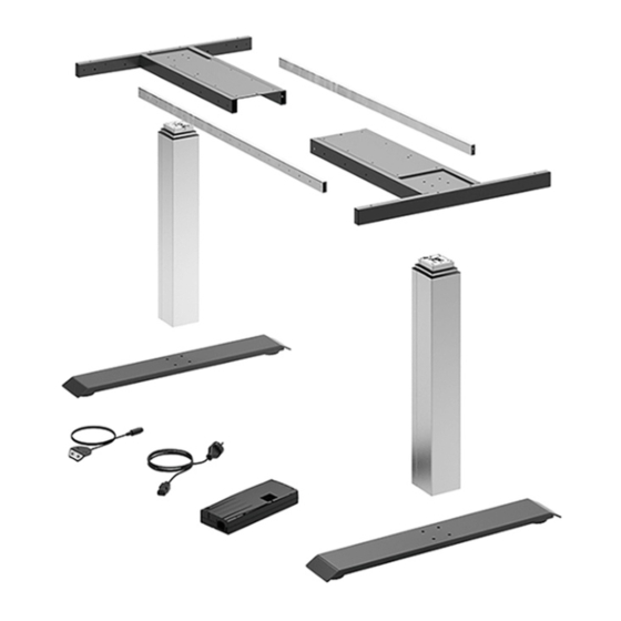
Page 8: Package Contents
Fig. 1: Example showing overall product Control unit Compact-e-3-EU control unit for LegaDrive LegaDrive. Compact-e-3-EU For up to 3 LegaDrive lifting columns and The following components (including cabling) are available for mains voltage 230V/50Hz. the system: Control unit Compact-e-3-US control unit for LegaDrive LegaDrive. -
Page 9: Liability
2. General 2.4 Liability Power supply cable Power supply cable for LegaDrive type F. Defects must only be rectified by competent personnel. LegaDrive EU "SchuKo" plug, mainly used in Germany, Austria, BeNeLux, France, Spain, Sweden, Norway, Finland etc. The manufacturer's liability is restricted to damage caused Power supply cable Power supply cable for LegaDrive type L. -
Page 10: Safety
3. Safety The following hazard zone markings are used in the operating The following hazard markings must be affixed directly to the and installation instructions (in accordance with Technical Rule desk where they are visible: for Working Places ASR A1.3): Danger Warning Danger from electric shock! -
Page 11: Safety Advice For The User Company
The lifting column system LegaDrive must only be operated if Immediately leave the area around the desk if it starts moving it is in proper working order. The user company will issue clear unintentionally. -
Page 12: Safety Advice For Maintenance Work
3. Safety Observe the lifting column system's ON time Do not make any structural changes to the lifting column system. of 10 %. This means, for example, that 1 minute of continuous operation must be followed by a pause of 9 minutes or that Observe the lifting column system‘s maximum ON time. -
Page 13: Particular Hazard Spots
3. Safety 3.6 Particular hazard spots Warning Risk of injury! When adjusting the desk support, make sure there is nobody in Never remove safety devices or render them inef- the vicinity. They could be injured. fective by making changes to the desk support! Malfunctions presenting a safety risk must be When setting up the desk support, make sure it is unable to col- rectified without delay! -
Page 14: Training/Instruction
3. Safety 3.8 Training/instruction As owner, you are obliged to inform and instruct the operating personnel in respect of applicable legal and accident prevention regulations as well as the safety devices fitted. In this context, bear in mind the varying specialised quali- fications of your staff. -
Page 15: Description Of The Product
Designation: Lifting column system for an electri- The lifting column system's controls are described below. cally height adjustable workstation Type: LegaDrive 4.2.1 Power supply cable Place of installation: Indoors (commercial) Power supply: 230 V; 50 Hz / 120 V; 60 Hz... -
Page 16: Control Unit
Please pay attention to the information under "Package contents". "Package contents". Fig. 7: LegaDrive Basic handset Fig. 5: Compact-e-2 control unit Fig. 8: LegaDrive Touch Basic handset Fig. 9: LegaDrive Touch Basic Inlay handset Fig. 6: Compact-e-3 control unit Fig. 10: LegaDrive Touch Inlay handset... -
Page 17: Fig. 11: Legadrive Touch Comfort Handset
4. Description of the product Fig. 11: LegaDrive Touch Comfort handset Remote handsets: Fig. 12. Remote handset Basic Fig. 13. Receiver module for remote handsets Note Remote handsets muss be firmly attached and used within sight of the furniture. Note Refer to the following sections for a detailed description of the functions. -
Page 18: Protective Guards
4. Description of the product 4.3 Protective guards 4.3.2 Software related protective guards Note Warning The primary safety function during height adjust- Risk of injury! ment is the dead man's principle with momenta- Despite a number of software based protective ry contact switch. -
Page 19: Transportation And Installation
Only move the lifting column / desk support in a dead state (dis- Danger connect power supply cable from power supply). Danger to life from electric current! The enclosures around the LegaDrive's compo- During installation nents must not be opened, removed or damaged. ·... -
Page 20: Installing Lifting Column
5. Transportation and installation 5.2.1 Installing lifting column Fit the lifting column to the skid and desk top support. To do this you will need the following tools: · 1 x hex driver, · 8 x M6 hexagon socket head screws per lifting column. Note Use M6 screws of appropriate length, paying attention to maximum screw length. -
Page 21: Installing Control Unit
2 - 4 x screws (depending on the type of handset) Position control unit at chosen position on desk top, To install the LegaDrive Basic handset under the desk top, pro- 2. Mark drill holes with pencil. ceed as follows: 1. -
Page 22: Installing Legadrive Touch Basic Handset
Install the handset at an appropriate position in the desk top. · 1 x screwdriver · 2 x screws To install the LegaDrive Touch Basic Inlay handset under the desk top, proceed as follows: To install the LegaDrive Touch Basic under the desk top, proceed 1. Unpack handset. as follows: Note 1. -
Page 23: Installing Legadrive Touch Inlay Handset
Install the handset at an appropriate position underneath the desk top. To do this you will need the following tools: · 1 x screwdriver To install the LegaDrive Touch Inlay handset under the desk top, proceed as follows: · 4 x screws 1. -
Page 24: Installing Legadrive Touch Comfort Handset
Attach the handset with 4 screws. To to this, use all 4 screw holes shown below. Fig. 31. Attaching LegaDrive Touch Comfort handset to example desk Fig. 30. Position of screw holes for installing LegaDrive Touch Comfort handset. Note The manufacturer recommends predrilling the 4 screw holes in the desk top. -
Page 25: Notes On Push To Open Function
5.2.3.5.1 Notes on the push-to-open feature 5.2.3.5.2 Notes on the control panel The LegaDrive Touch Comfort manual switch has a push-to-open To prevent damage, the control panel is designed so that it deta- feature which automatically extends the control panel when it is ches from its anchorage under unusually high pressure (forces pushed. -
Page 26: Installing The Remote Handset Basic
5. Transportation and installation 5.2.3.6 Installing the remote handset Basic Note The following screw types should be used for attaching the remote handset Basic: - Cylinder head screws - Round-head screws - Flat-head screws Fig. 38. Remote handset Basic Max. thread diameter: 4.5 mm Max. -
Page 27: Start-Up
6. Start-up Startup includes those activities that are involved in using the lifting column system LegaDrive to adjust the height of an elec- trically height-adjustable workstation. Before the system can be started up, the following items must have ben installed: ·... -
Page 28: Starting Up For The First Time
Before starting up the desk support for the first time, observe the Danger following: Danger to life! · Check to make sure the lifting column system LegaDrive Danger to life from electric shock! has been installed in accordance with the regulations The power supply cable must only be plugged specified! in once all components are connected to the ·... -
Page 29: Plugging In Handset
6. Start-up 6.2.2 Plugging in handset 6.2.2.2 Replacing the battery The remote handsets are operated with a lithium button cell (CR Plug the handset cable into the 7-pin socket. 2032 included in delivery). Note Immediate remove used button cells (batteries) and dispose of them in an environmentally friendly manner. -
Page 30: Plugging In Power Supply Cable
1: a LegaDrive COMPACT-e-2 type control unit. When installing the power supply, it must be en- · 2: a desk support with two LegaDrive lifting columns sured that the control unit can be disconnected · 3: a LegaDrive Basic type handset from the power supply at any time. -
Page 31: Operation
7. Operation 7.1 Basic functions To ensure that the LegaDrive systems operates safely, please observe the following safety advice: Note The control unit provides a wide range of functions. The availability of some functions, Danger however, depends on the handset used. -
Page 32: Upward Desk Top Movement
7. Operation 7.1.1 Upward desk top movement 7.1.2 Downward desk top movement The function provides an easy way of adjusting the desk top to a The function provides an easy way of adjusting the desk top to a higher position. To do this, proceed as follows: lower position. -
Page 33: Display Functions
Fig. 50. The LegaDrive Touch Comfort handset lock is activated and deactivated by swiping to the left or right SAVE Fig. 51. The LegaDrive Touch Inlay handset lock is activated and deacti- vated by swiping to the left or right Note The swiping direction is irrelevant. -
Page 34: Extended Functions
7. Operation 7.4 Extended functions 7.4.1 Memorising a desk top position This function memorises a defined desk top height (one desk top Note height can be memorised per memory position button). To memo- You can only use the following control unit rise a desk top position, proceed as follows: functions if you have a handset with memory position buttons and a memory button. -
Page 35: Adjusting Desk Top To A Memorised Position
7. Operation 7.4.2 Adjusting desk top to a memorised position 7.4.3 Changing desk top position height display This function is used for adjusting the height indicated on the This function lets you move the desk top to a memorised desk top handset display to the desk top's actual height. -
Page 36: Manual Reset
7. Operation 7.4.4 Manual reset 7.5 Software related functions If the actual desk top position no longer matches the desk top Note position displayed or if a previously configured control unit is The control unit is parameterised by software be- used at another electrically height adjustable workstation of fore leaving the factory. -
Page 37: Safety Zone
7. Operation 7.5.3 Safety zone 7.5.4 Pedestal stop and shelf stop positions This function produces a safety stop at a defined desk top positi- These two features can be used to limit the desk's travelling ran- on (configured by software). The safety stop works as follows: ge (e.g. - Page 38 7. Operation If you have a handset with display (such as LegaDrive Touch Inlay To deactivate a pedestal stop / shelf stop position, proceed as or LegaDrive Touch Comfort), proceed as follows: follows: Button Function Note These steps must be performed separately for a Move the desk top to the position you pedestal stop position and a shelf stop position.
-
Page 39: Plug Detection
7. Operation 7.5.5 Plug detection 7.5.7 Collision detection (Drive back) The control unit detects whether a lifting column is plugged in at The desk top automatically changes its position by a defined dis- a specific socket. The control unit also detects whether a lifting tance in the opposite direction after triggering a safety function column has been changed. -
Page 40: Changing Desk Height Unit (Cm Or Inch)
7. Operation 7.5.8 Changing desk height unit (cm or inch) 7.5.9 Returning control unit to factory settings (S0 menu) This function allows you to return the control unit to factory This function lets you change the memory handset display from settings. - Page 41 7. Operation To be able to use the control unit again after changing a lifting If a handset with only one up and one down button is used, column‘s configuration in this way, proceed as follows: proceed as follows: Button Function Note This is possible for control units with Revision...
-
Page 42: Cascading
Parameters must first be set to define whether a control unit is used for cascading. Functions may vary slightly from those of an individual control unit. Note For further information on cascading please refer to the manufacturer's separate operating inst- ructions on "Cascading LegaDrive control units". -
Page 43: Troubleshooting
8. Troubleshooting 8.1 Safety advice Lifting column system malfunctions must only be rectified by Warning specialists instructed to do so by the person responsible. Safety regulations while identifying the source of malfunction and rectifying malfunc- In identifying the source of malfunction attention must be paid tion! to the entire area surrounding the lifting column system. -
Page 44: Malfunctions
8. Troubleshooting 8.2 Malfunctions 8.2.1 Potential malfunctions and how to remedy them This section provides you with detailed information on the fol- Lifting columns not working lowing subjects: Possible cause Remedy · Potential malfunctions and how to remedy them Power supply cable Plug the power supply cable into the ·... -
Page 45: Faults Indicated On The Handset Display
8. Troubleshooting 8.2.2 Faults indicated on the handset display Display not working (buttons working) The display shows HOT. Possible cause Remedy Possible cause Remedy Cable is faulty Change the handset The control unit is protec- Wait for the control unit to cool Display is faulty Change the handset down and the HOT message to go... -
Page 46: Control Click Codes
8. Troubleshooting Description Remedy Note PowerFail Detection is identifying power failures 00 Internal fault on Switch the control unit off. channel 1 Contact customer service. and saving all relevant data before the voltage 01 Internal fault on drops below a critical level. channel 2 In a few cases of exception data cannot be 02 Internal fault on... -
Page 47: Servicing And Maintenance
(recommended). · Make sure the lifting column system LegaDrive is prevented from switching back on unintenti- The life of the lifting column system LegaDrive will depend on onally. proper use and adherence to regular servicing intervals. · Follow the safety advice and accident preven-... - Page 48 Risk of injury from failure to observe safety other measures! The enclosures around the LegaDrive's compo- After carrying out maintenance work, always: nents must not be opened, removed or damaged. · check all screw connections to make sure they are...
-
Page 49: Checking Safety Devices
9. Servicing and maintenance 9.2 Checking safety devices 9.3 Labelling, information signs Regularly check safety devices to make sure they are complete Labelling/information signs must be and in proper working order. · cleaned with a cloth, · checked for secure attachment and legibility, ·... -
Page 50: Taking Out Of Service
10. Taking out of service When taking the system out of service the mains power cable must be disconnected from the mains power supply. Danger Danger from electric shock! Work on electrical equipment must only be carried out by authorised electricians! -
Page 51: Disposal
11. Disposal 11.1 Protecting the environment Sort materials before disposal and dispose of them in an environ- Caution mentally friendly manner. Electrical and electronic components Caution! must be disposed of as hazardous waste. The obligations prescribed in law with regard to avoiding waste and proper recycling/disposal must be met when carrying out any work on the lifting column system! -
Page 52: Scrapping
11. Disposal 11.2 Scrapping If the lifting columns system LegaDrive is ever taken out of service for good, the laws and regulations in force at that time of disposal must be observed and met. The entire energy supply system must also be dismantled and removed at the time of final shutdown and disposal. -
Page 53: Ec Declaration Of Incorporation
The national authorities may, if they so request, be provided with specific documents in paper or electric form. Note: The incomplete machine of type „LegaDrive“ may only be commissioned when it has been established that a machine in which „LegaDrive“ has been installed complies with the provisions of the machine directive. - Page 54 Paul Hettich GmbH & Co. KG Vahrenkampstr. 12-16 32278 Kirchlengern...
Need help?
Do you have a question about the LegaDrive and is the answer not in the manual?
Questions and answers