Extron electronics Quantum Ultra User Manual
Videowall processing system
Hide thumbs
Also See for Quantum Ultra:
- User manual (85 pages) ,
- Quick start manual (3 pages) ,
- Replacing manual (4 pages)

Related Manuals for Extron electronics Quantum Ultra


Summary of Contents for Extron electronics Quantum Ultra
- Page 1 User Guide Videowall Processors Quantum Ultra Videowall Processing System 68-2760-01 Rev. E 05 19...
- Page 2 Safety Instructions Safety Instructions • English Istruzioni di sicurezza • Italiano AVVERTENZA: Il simbolo, , se usato sul prodotto, serve ad This symbol, , when used on the product, is intended to WARNING avvertire l’utente della presenza di tensione non isolata pericolosa alert the user of the presence of uninsulated dangerous voltage within the all’interno del contenitore del prodotto che può...
- Page 3 ついては、 エクス トロンのウェブサイ ト より 『Extron Safety www.extron.com and Regulatory Compliance Guide』 (P/N 68-290-01) をご覧ください。 Copyright © 2017-2019 Extron Electronics. All rights reserved. www.extron.com Trademarks All trademarks mentioned in this guide are the properties of their respective owners. The following registered trademarks ( ®...
- Page 4 FCC Class A Notice This equipment has been tested and found to comply with the limits for a Class A digital device, pursuant to part 15 of the FCC rules. The Class A limits provide reasonable protection against harmful interference when the equipment is operated in a commercial environment.
- Page 5 Conventions Used in this Guide Notifications The following notifications are used in this guide: DANGER: • Will result in serious injury or death. • Entraînera des blessures graves ou la mort. WARNING: Potential risk of severe injury or death. AVERTISSEMENT : Risque potentiel de blessure grave ou de mort. CAUTION: Risk of minor personal injury.
-
Page 7: Table Of Contents
Loading Image Files .......... 38 Quantum Ultra 610 .......... 80 Updating the Password ........40 Replacing a Disk Drive — Quantum Ultra 610 ... 84 Updating Firmware ........... 41 Replacing the System Board Computer (SBC) Downloading a Firmware File ......41 Assembly —... - Page 8 Mounting ............90 UL Guidelines for Rack Mounting ...... 90 Rack Mounting the Quantum Ultra ....90 Rack Mounting Requirements ....... 91 Rack Mounting Procedure ......91 Extron Warranty ..........93 viii Quantum Ultra Videowall Processing System • Contents...
-
Page 9: Introduction
60 frames per second. The Quantum Ultra 610 is a 6U, 10-slot card frame, while the Quantum Ultra 305 is a 3U frame with 5 card slots. Each HDMI input card contains four HDMI connectors, while each IN SMD 100 card has two LAN connectors, each of which can be connected to a network to enable decoding of multiple streams. -
Page 10: Features
• Scalable 4K @ 60 Hz videowall processing for display systems of any size — Quantum Ultra supports videowalls up to 36 screens in size from a single processor. Additional processors can be configured and operated as a single system to accommodate larger videowalls.. - Page 11 HDMI and DVI displays. • Up to 64 video and graphic windows per output card — Quantum Ultra offers extensive windowing capabilities, with the ability to display up to 64 video, image, and clock windows from each output card.
- Page 12 • and vertical sizing, horizontal and vertical positioning, zoom, and overscan. • Internal video test patterns for calibration and setup — Quantum Ultra offers several dynamically-generated video test patterns to facilitate proper system setup and calibration of display devices. Supports direct decoding of H.264 streams for presentation on the videowall •...
-
Page 13: Hyperlane Bus For Source Transfer
RS-232 insertion from the Ethernet control port (OUT4DTP card) — System • level device control to all remote locations via the Quantum Ultra control port, providing comprehensive control of endpoints and attached devices without needing additional equipment. -
Page 14: Virtual Network Computing (Vnc)
The size of the VNC window on the Quantum Ultra output and the number of VNC sources simultaneously displayed also influence the refresh rate of the content. -
Page 15: Application Diagrams
Application Diagrams The following application diagrams show examples of how the Quantum Ultra can be connected. Extron HDMI HDMI Quantum Ultra Ultra-high Bandwidth 4K Videowall Processor QUANTUM ULTRA 610 INPUTS QUANTUM IN4HDMI INPUTS QUANTUM IN4HDMI INPUTS QUANTUM IN4HDMI OUTPUTS QUANTUM OUT4HDMI... - Page 16 PWR OUT = 6W Extron 1 2 3 4 WiFi IPCP Pro 250 IP Link Control Processor 4K PC WiFi 1 2 3 4 4K PC Figure 2. Application Diagram with DTP Outputs Quantum Ultra Videowall Processing System • Introduction...
-
Page 17: Installation And Configuration
RS-232 Insertion — DTP Outputs Only Installation Steps The Quantum Ultra processor can be mounted in a 19-inch equipment rack or placed on furniture. To install and set up the Quantum Ultra processor for a videowall, follow the steps below (see Application Diagrams on page 7 for connection examples). -
Page 18: Front Panel Features - Quantum Ultra 305
LAN A: 192.168.254.254. LAN B: 192.168.1.254 • Set a new IP address for the Quantum Ultra using any of the following: VCS program — The Videowall Configuration Software for the Quantum Ultra • can be downloaded from the Extron website (see... -
Page 19: Rear Panel Features
PRIMARY POWER connector — Connect AC power to this IEC connector for the primary power supply. REDUNDANT POWER connector — (Optional, Quantum Ultra 610 only) Connect a second AC power source to this IEC connector for the secondary power supply to provide uninterrupted operation in the event of failure of the primary supply. - Page 20 If the unit is on, pressing and holding this switch for approximately 5 seconds powers it down. NOTE: If you are logged into the Quantum Ultra device operating system, a momentary (>1 second) press of this switch powers off the device.
-
Page 21: Hdmi Lockit Cable Lacing Brackets
Extron representative. Card Locations When the Quantum Ultra is assembled at the factory, all the input cards are installed in slots above the output cards in the chassis. If installing cards yourself, do not intersperse input cards with output cards. -
Page 22: Inputs
Inputs The input cards available for the Quantum Ultra include: HDMI (IN4HDMI) — Each card contains four HDMI connectors. • • IP (IN SMD 100) — Each card contains two LAN connectors. Source down-scaling Each input card has an on-board scaler that can down-scale the video sources in size to 1/32 of the original size (horizontally, vertically, or both). - Page 23 Processed Eight unique at 30 Hz mini cation sizes for one source Figure 8. Example of One Input at 1080p, 60 Hz, on One Input Card Quantum Ultra Videowall Processing System • Installation and Configuration...
- Page 24 Processed at 15 Hz Four unique mini cation sizes for one 4K grouped source Figure 11. Example of One 4K Input, 60 Hz, Column or Quad Format, on One Input Card Quantum Ultra Videowall Processing System • Installation and Configuration...
- Page 25 300 MHz signals, connector 3 is disabled. Digital video sources such as computers, cameras, Blu-ray™ or DVD players, and video servers can be connected to the Quantum Ultra processor through one or more of the HDMI input cards. These input cards are HDCP-compliant when used with HDMI output cards and HDCP-compliant displays.
- Page 26 Figure 13. Input Rotation The Quantum Ultra input card can support rotation of two 1920x1080 sources at 60 Hz or one 3840x2160 source at 30 Hz. Additional sources can be rotated, but the processing frame rate is reduced in half to remain within the available bandwidth of the card (see the following examples).
- Page 27 One unique mini cation size for one source Two unique mini cation Processed at 15 Hz sizes for one source Figure 17. Example of One Rotated 4K Input, 30 Hz, on One Input Card Quantum Ultra Videowall Processing System • Installation and Configuration...
- Page 28 The software lets you view the current EDID that has been set for each input. If no project file has been saved on the Quantum Ultra, the default EDID setting of 1080p @ 60 Hz is applied (see the VCS Help File, provided with the software, for details on selecting and monitoring EDID).
- Page 29 MPEG4 part 2 SP (<10 Mbps) • • MPEG4 part 2 ASP (<10 Mbps) • MPEG4 part 10 (AVC) H.264 BP, MP, HiP up to level 4.2 (<62.5 Mbps, 1 sec) • JPEG over RTP Quantum Ultra Videowall Processing System • Installation and Configuration...
- Page 30 SDP (Session Description Protocol – RFC 4145 and 4566) — Allows RTSP initialization of the Quantum Ultra IP card using a locally stored SDP file to function as a browser helper application. In practice, the IP card may use the DESCRIBE method to initialize RTSP.
-
Page 31: Outputs
Outputs The Quantum Ultra HDMI and DTP output cards integrate all inputs to be displayed in a layout that you define using the control software (see the VCS Help File for information on using the program to set up displays). They also provide up-scaling of sources. - Page 32 Output Channel Configuration Example The following table shows all the output resolutions and refresh rates supported on Quantum Ultra and which connectors on the output cards support each resolution. All — Indicates resolutions and rates supported on all connectors on the output cards.
- Page 33 Using the VCS program, you can add custom output resolutions based on EDID that have either been captured from the connected sink device on an output or uploaded (see the VCS Help File for information on managing EDID). Quantum Ultra Videowall Processing System • Installation and Configuration...
- Page 34 23 and 24 on the previous page, display 1 is located at x=00 and y=00 (upper-left corner) on the videowall, the Quantum Ultra is named , the display is connected to the output card in slot 5, output connector 1 QU610-FFFFFF (5.1), and the wall output resolution is 1920x1080 (1080p).
- Page 35 • Digital output format A videowall design can consist of multiple canvases. A canvas can contain connectors on any output board on any Quantum Ultra chassis, and multiple canvases can be defined on a single output card. Canvas 2 Canvas 1...
- Page 36 HDCP mode Using VCS, you can select the HDCP mode, which specifies whether the Quantum Ultra encrypts source content. The Quantum Ultra can be set to always encrypt HDMI data, to never encrypt ( option), or to not encrypt after attempting unsuccessfully to exchange keys with the target display for 1 minute (see the VCS Help File for instructions on using this option).
- Page 37 Maximum output signals for each output card The following examples show the number of output signals that are supported on each output card, depending on resolution, refresh rate, and format (standard, column, or quad). Quantum Ultra Videowall Processing System • Installation and Configuration...
- Page 38 If the displays in the videowall are installed in a portrait orientation, the output signal from the Quantum Ultra can be rotated to support the rotated displays. In contrast to input rotation, which rotates the source content within a window, output rotation affects the entire output signal, which includes all sources, window text, images, and HDCP messaging.
-
Page 39: Adjusting For Mullion Compensation And Edge Blending
The settings are applicable to all edges within the canvas. See the VCS Help File for instructions on adjusting to compensate for mullion and edge blending. Quantum Ultra Videowall Processing System • Installation and Configuration... -
Page 40: Connecting To A Network
Connect a computer that is running the Videowall Configuration Software to the Ethernet (10/100/1000Base-T) LAN A or LAN B port on the rear panel to enable you to control the Quantum Ultra processor and to set up videowall applications via the computer. -
Page 41: Rs-232 Insertion - Dtp Outputs Only
The control signals can be inserted two ways: • Ethernet to RS-232 insertion — A control signal applied to the Quantum Ultra LAN A port can be routed to any OVER TP port (see “Ethernet to RS-232 Insertion”). The RS-232 insertion port number is entered as the Telnet port number when you establish communication with the insertion port. -
Page 42: Captive Screw Signal Insertion
Extron IPCP Pro control processor provides control of a display via the Quantum Ultra. Configure this type of insertion as follows: Connect a serial cable from a control processor to the 3-pole Remote RS-232 captive screw port on the Quantum Ultra rear panel. -
Page 43: Selecting The Insertion Method And Rs-232 Protocol
(see the VCS Help File for detailed configuration instructions). NOTE: The insert connections, whether inserted via Ethernet or captive screw connectors, can support up to a 115,200 baud rate. Quantum Ultra Videowall Processing System • Installation and Configuration... -
Page 44: Operation
Operation The Quantum Ultra processor is a host device with an embedded operating system. The Quantum Ultra Control Panel is a program that resides on the Quantum Ultra operating system and enables you to perform various setup and maintenance tasks, such as setting the processor IP address, resetting the device, or updating the firmware. - Page 45 Enter the password where indicated on the login window (by default, the password is extron main window opens on the monitor, in front of Quantum Ultra Control Panel a background image of the Quantum Ultra. From this window, you can access all common tasks. NOTE: If the window is closed, press <...
-
Page 46: Control Panel Buttons
Control Panel Buttons The following buttons give you access to set up and manage the Quantum Ultra via the Control Panel (see figure 37 on the previous page). NOTE: When you click a Control Panel button, a password prompt appears. - Page 47 . Yours may be a different drive. Figure 38. USB Flash Drive Containing Picture Files On the USB drive, locate the image files to be loaded to the Quantum Ultra and drag or copy them to the folder on the Quantum Ultra drive.
-
Page 48: Updating The Password
Figure 41. Password Reboot Prompt Click to reboot. (If you click , the new password remains in effect only until Cancel the system is shut down.) Quantum Ultra Videowall Processing System • Operation... -
Page 49: Updating Firmware
Updating Firmware If it becomes necessary to update the firmware on your Quantum Ultra, you can obtain new firmware at www.extron.com and upload it to the unit. Downloading a Firmware File On the Extron website, hover the mouse pointer over the tab (see figure 42,... -
Page 50: Uploading A Firmware File
Uploading a Firmware File To upload a new firmware file to the Quantum Ultra: Copy the new, unpacked firmware file to a USB flash drive or to a CD for use in a secure location. - Page 51 Double-click on the firmware file or select it and click . The Quantum Ultra Open firmware file must have a .gpg extension. Figure 46. Selecting the Firmware File on the D: Drive Quantum Ultra Videowall Processing System • Operation...
- Page 52 ) at the bottom of the screen lets you know approximately how much time remains for the installation. Figure 48. Installation Progress Screen When the installation is completed, appears in the upper-left corner of the Success! screen. Quantum Ultra Videowall Processing System • Operation...
-
Page 53: Modifying Network Settings
Settings Figure 50. Network Settings for LAN A Port If desired, enter a name of 1 to 15 characters for your Quantum Ultra. Only letters, numbers, and the hyphen ( ) can be used in this name. NOTE: All letters in the are displayed in uppercase. -
Page 54: Resetting The Device
— Reset Device Settings (Retain TCP/IP Settings and Image Files) Resets the Quantum Ultra to its factory default settings while keeping the IP addresses and other settings that have been entered, plus any image files that have been uploaded. This is the default. -
Page 55: Service Mode
Service Mode In service mode, you can access the Quantum Ultra drives as well as the operating system Control Panel. To enter service mode: On the Quantum Ultra main window, click Control Panel Service Mode On the screen, enter your system password where indicated... -
Page 56: Committing Changes To Memory
Committing Changes to Memory The Quantum Ultra Control Panel enables you to commit (save) to memory all changes made to the drive and operating system configuration during the session. These saved settings remain in effect the next time the Quantum Ultra is powered on. -
Page 57: Remote Configuration And Control
All responses from the Quantum Ultra to the host end with a carriage return and a line feed (CR/LF = ] ), indicating the end of the response character string (one or more characters). -
Page 58: Quantum Ultra-Initiated Messages
Quantum Ultra-initiated Messages When a local event such as a software selection or adjustment takes place, the Quantum Ultra responds by sending a message to the host. No response is required from the host. Examples of a Quantum Ultra-initiated messages are: X2% ] Window preset X2% for canvas X# recalled. -
Page 59: Symbol Definitions
= Window selection — 1 through 999 0 = All windows (for window mute only) Response is three digits with leading zeros. = Model name — Quantum Ultra 610 or Quantum Ultra 305 X& Part number of the product Quantum Ultra 610 —... - Page 60 Leading zeros in each of the four octets are optional in setting values, and are suppressed in returned values. X11$ = Gateway IP address (nnn.nnn.nnn.nnn) Leading zeros in each of the four octets are optional in setting values, and are suppressed in returned values. Quantum Ultra Videowall Processing System • Remote Configuration and Control...
- Page 61 Example: The Quantum Ultra can send out a notice of a change in some setting without receiving a query via a PC or a control system. That change could have been a result of an internal process or a selection made via the VCS program.
-
Page 62: Command And Response Table For Sis Commands
1000-9999 = VNC, image, text, and clock sources defined in the system Name or text label (for inputs) — Up to 32 characters. Invalid characters: \ / : * ? , > |. Quantum Ultra Videowall Processing System • Remote Configuration and Control... - Page 63 Source Text string — 1-64 characters. Invalid characters: " ' \ ` RGB color value for source text string or text background — 0-255, in the format {red * green * blue} Text size in points — 8 through 251 Quantum Ultra Videowall Processing System • Remote Configuration and Control...
- Page 64 Response is six digits, padded with zeros. Window mute: 0 = Unmute (default), 1 = Mute window. Window priority position — 1 through 999. Response is three digits padded with zeros. 1 = Front. ` Quantum Ultra Videowall Processing System • Remote Configuration and Control...
- Page 65 0 = All windows (for window mute only) Horizontal and vertical position (Limits depend on input or output resolutions.) Response is six digits with leading + or -, padded with zeros. Quantum Ultra Videowall Processing System • Remote Configuration and Control...
- Page 66 Response is six digits with leading + or -, padded with zeros. X1& Horizontal and vertical size (Limits depend on input or output resolutions.) Response is six digits, padded with zeros. Quantum Ultra Videowall Processing System • Remote Configuration and Control...
- Page 67 Window preset number — 1 through 128. Response is three digits padded with zeros. Input preset number: 1 through 128. Response is three digits padded with zeros. Window border style preset number: 000 through 127. 000 = No border. Quantum Ultra Videowall Processing System • Remote Configuration and Control...
- Page 68 Reboot the system and retain 1 BOOT Boot 1 network settings the network settings. Reboot system and Reboot the system and discard 3 BOOT Boot 3 discard network settings the network setting changes. Quantum Ultra Videowall Processing System • Remote Configuration and Control...
- Page 69 20Stat • KEY: Quantum Ultra 610 or Quantum Ultra 305 X& Quantum Ultra part number: Quantum Ultra 610 = 60-1571-01, Quantum Ultra 305 = 60-1734-01 Internal temperature in degrees Celsius. Quantum Ultra Videowall Processing System • Remote Configuration and Control...
- Page 70 View the name of the unit. In verbose modes 2 and 3: X11@ ] Ipn • KEY: X11@ Unit name: Text string of up to 15 characters: A-Z, 0-9, and hyphen (-). Quantum Ultra Videowall Processing System • Remote Configuration and Control...
- Page 71 Verbose mode: 0 = None (default for Telnet), 1 = Verbose mode on (default for RS-232 and USB), 2 = Verbose mode off, tagged responses enabled for queries, 3 = Verbose mode and tagged responses for queries enabled (see Verbose mode command definition on page 53). Quantum Ultra Videowall Processing System • Remote Configuration and Control...
- Page 72 Network interface: 1 = LAN A port, 2 = LAN B port X17& Prefix representing subnet mask bits (subnet mask value in CISG commands). Default = /24, which represents the default subnet mask, 255.255.255.0. Quantum Ultra Videowall Processing System • Remote Configuration and Control...
- Page 73 **** password, **** is omitted from the response. KEY: X13# Administrator or user password, 128 characters maximum. / \ | * and space characters are not allowed. Passwords are case-sensitive. Quantum Ultra Videowall Processing System • Remote Configuration and Control...
-
Page 74: Videowall Configuration Software (Vcs) Program
Videowall Configuration Software (VCS) Program The Extron VCS program is a PC-based program for the Quantum Ultra that provides a convenient way to configure the videowall. System configuration is broken down into logical tasks, including output and wall configuration, source setup, preset design, and EDID Minder. - Page 75 By default, the installation places the program files at: C:\Program Files (x86)\Extron\Extron VCS If there is not already an Extron folder in your Program Files or Program Files x86 folder, the installation program creates it as well. Quantum Ultra Videowall Processing System • Remote Configuration and Control...
-
Page 76: Starting The Configuration Program
Quantum Ultra chassis. Click to confirm your selection. the screen closes. Network Adapter Locate your Quantum Ultra on this list and click the button ( Add to System at the left of the device name. Connection information is displayed in the System panel ( ). - Page 77 In the field, enter the address of the Quantum Ultra to be connected IP Address and select the radio button. Pull from Hardware Click . The connection information for the device is displayed in the System panel (see figure , on the previous page).
-
Page 78: Maintenance
Maintenance The Quantum Ultra 610 has several parts that you can replace, should they fail, wear out, or no longer meet your requirement. On the Quantum Ultra 305, only the input and output cards can be replaced. This section provides instructions for replacing these parts, which you can order from your Extron representative or by going to www.extron.com. -
Page 79: Accessing The Front Panel
Accessing the Front Panel To access the Quantum Ultra front panel, open the front panel door as follows: Insert a coin, such as a penny, in the slot on the front panel lock and rotate it one quarter turn counterclockwise, until the dot above the slot faces... -
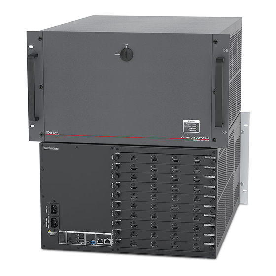
Page 80: Front Panel Features - Quantum Ultra 610
Primary power supply — Main power supply that provides power to the Quantum Ultra. This power supply can be replaced if necessary without powering off the system (hot-swappable) (see Replacing the Primary Power Supply on page 76). Quantum Ultra Videowall Processing System • Maintenance — Quantum Ultra 610 Only... -
Page 81: Replacing Input And Output Cards
) and the SBC, which runs the Quantum Ultra firmware. Replacing Input and Output Cards When you place an order for a Quantum Ultra, you specify how many input and output cards are loaded when the product is shipped. However, if your application changes, you may want to purchase additional cards from Extron and replace one or more of the original cards. - Page 82 NOTE: The card is not completely in place until you hear or feel it snap into the connector at the end of the card. If you do not feel it snap into position, press on it more firmly until you do. Quantum Ultra Videowall Processing System • Maintenance — Quantum Ultra 610 Only...
-
Page 83: Replacing A Power Supply - Quantum Ultra 610
When finished removing and installing cards, power the unit on. Replacing a Power Supply — Quantum Ultra 610 Quantum Ultra has a primary and a redundant power supply unit (PSU) to ensure continued, uninterrupted operation if a power supply should fail. However, if a power supply does fail, you should replace it at your earliest convenience. -
Page 84: Replacing The Primary Power Supply
Remove the cover panel ( Rotate the lever to the right ( ) until it is in a horizontal position, parallel to the top and bottom of the unit. Quantum Ultra Videowall Processing System • Maintenance — Quantum Ultra 610 Only... - Page 85 Rotating the Latch and Sliding the Power Supply to the Right and Lift the power supply up slightly and slide it toward you, out of the chassis ( Quantum Ultra Videowall Processing System • Maintenance — Quantum Ultra 610 Only...
- Page 86 Slide the round end of the lever ( 2 ) between the two pegs ( 1 ) when installing a power supply. Figure 71. Positioning the Lever between the Two Pegs on the Chassis Quantum Ultra Videowall Processing System • Maintenance — Quantum Ultra 610 Only...
-
Page 87: Replacing The Redundant Power Supply
(see figure 73). (Retain the back plate and screws to reattach the strip in step 6). Remove three screws. Figure 73. Removing the Metal Strip from the Failed Power Supply Back Panel Quantum Ultra Videowall Processing System • Maintenance — Quantum Ultra 610 Only... -
Page 88: Replacing The Power Supply (Top) Fan - Quantum Ultra 610
The largest (top) fan cools the power supplies. If this power supply fan fails, you can order www.extron.com a new one from and replace it as described in this section. This fan is hot-swappable, that is, it can be replaced while the Quantum Ultra is operating, without the need to power down the unit. ATTENTION: •... - Page 89 Les vis doivent être serrées avec un tournevis après la première installation et l’accès postérieur au panneau. Disconnect the small fan cables ( Cables Loosen the thumbscrew. Disconnect the cables. Figure 75. Detaching the Top Fan Quantum Ultra Videowall Processing System • Maintenance — Quantum Ultra 610 Only...
- Page 90 The replacement fan has two tabs on the back (see figure 77). These tabs fit into two slots in the back of the fan compartment of the chassis (see figure 78 on the next page). Tabs Figure 77. Tabs on the Top Fan Quantum Ultra Videowall Processing System • Maintenance — Quantum Ultra 610 Only...
- Page 91 Figure 79. Inserting the Replacement Fan When the fan unit is in place, use a screwdriver to tighten the thumbscrew. Connect the two fan cables. Quantum Ultra Videowall Processing System • Maintenance — Quantum Ultra 610 Only...
-
Page 92: Replacing A Disk Drive - Quantum Ultra 610
Thumbscrews should be tightened with a screwdriver after both initial installation and subsequent access to the panel. • Les vis doivent être serrées avec un tournevis après la première installation et l’accès postérieur au panneau. Quantum Ultra Videowall Processing System • Maintenance — Quantum Ultra 610 Only... - Page 93 Quantum Ultra Videowall Processing System • Maintenance — Quantum Ultra 610 Only...
- Page 94 ) insert into the receptacles on the board at the back of the compartment ( Use a screwdriver to tighten the thumbscrew and secure the drive in place. Power the system back on. Quantum Ultra Videowall Processing System • Maintenance — Quantum Ultra 610 Only...
-
Page 95: Replacing The System Board Computer (Sbc) Assembly - Quantum Ultra 610
Unplug the lower fan cable from the 3-pin connector at the right front corner of the SBC assembly (see figure 83). Fan Cable Figure 83. Unplugging the Fan Cable Quantum Ultra Videowall Processing System • Maintenance — Quantum Ultra 610 Only... - Page 96 Pull the handle on the SBC ( ) toward you until the assembly is free of the chassis. Loosen the thumbscrews (2). Figure 84. Removing the SBC Assembly Quantum Ultra Videowall Processing System • Maintenance — Quantum Ultra 610 Only...
-
Page 97: Installing A New Sbc Assembly
87 for the location). Reinstall the hard drives on the SBC assembly (see Replacing a Disk Drive — Quantum Ultra 610 on page 84). Power the system back on. Quantum Ultra Videowall Processing System • Maintenance — Quantum Ultra 610 Only... -
Page 98: Mounting
(such as the use of power strips). Rack Mounting the Quantum Ultra The Quantum Ultra processor can be placed on a tabletop or mounted in a rack (recommended). CAUTION: The Quantum Ultra 610 chassis is very heavy. When it is fully populated with input and output cards, its weight can be up to 59.8 lbs (28 kg). -
Page 99: Rack Mounting Requirements
Support Always use additional support at the sides or rear of the Quantum Ultra unit, attached to both the front and rear rack posts. Ensure that the shelf or other mounting accessories can support the full weight of the unit. - Page 100 Because of the weight of the Quantum Ultra processor, you must provide additional support for the unit from the back. • Compte tenu du poids du processeur Quantum Ultra, vous devez fournir plus de capacités de support à l’arrière de l’unité. Quantum Ultra Videowall Processing System • Mounting...
-
Page 101: Extron Warranty
Extron Electronics makes no further warranties either expressed or implied with respect to the product and its quality, performance, merchantability, or fitness for any particular use. In no event will Extron Electronics be liable for direct, indirect, or consequential damages resulting from any defect in this product even if Extron Electronics has been advised of such damage.
Need help?
Do you have a question about the Quantum Ultra and is the answer not in the manual?
Questions and answers