
Related Manuals for Extron electronics IPCP Pro Q xi Series


Summary of Contents for Extron electronics IPCP Pro Q xi Series
- Page 1 IPCP Pro Q xi and xi Series IP Link Pro xi Control Processors ® User Guide IP Link Pro xi Products 68-3496-01, Rev. E 10 24...
-
Page 2: Safety Instructions
Safety Instructions Safety Instructions • English Instructions de sécurité • Français AVERTISSEMENT : Ce pictogramme, , lorsqu’il est utilisé sur le WARNING: This symbol, , when used on the product, is intended to produit, signale à l’utilisateur la présence à l’intérieur du boîtier du produit alert the user of the presence of uninsulated dangerous voltage within the d’une tension électrique dangereuse susceptible de provoquer un choc product’s enclosure that may present a risk of electric shock. - Page 3 • 安全说明 简体中文 警告: 产品上的这个标志意在警告用户, 该产品机壳内有暴露的危险 电压, 有触电危险。 注意: 产品上的这个标志意在提示用户, 设备随附的用户手册中有重 要的操作和维护(维修)说明。 关于我们产品的安全指南、遵循的规范、EMI/EMF 的兼容性、无障碍使 用的特性等相关内容, 敬请访问 Extron 网站 , www.extron.com,参见 Extron 安全规范指南,产品编 号 68-290-01 。 安全記事 • 繁體中文 안전 지침 • 한국어 경고: 이 기호 가 제품에 사용될 경우, 제품의 인클로저 내에 있는 警告: 若產品上使用此符號,...
-
Page 4: Fcc Class A Notice
FCC Class A Notice This equipment has been tested and found to comply with the limits for a Class A digital device, pursuant to part 15 of the FCC rules. The Class A limits provide reasonable protection against harmful interference when the equipment is operated in a commercial environment. -
Page 5: Specifications Availability
Conventions Used in this Guide Notifications The following notifications are used in this guide: CAUTION: Risk of minor personal injury. ATTENTION : Risque de blessure mineure. ATTENTION: • Risk of property damage. • Risque de dommages matériels. NOTE: A note draws attention to important information. TIP: A tip provides a suggestion to make working with the application easier. -
Page 7: Table Of Contents
Contents Introduction ............................. 1 Before You Begin ..............................1 What This Guide Covers ..........................1 Conventions Used in This Guide ........................1 Important Information You Need Before Installation ..................1 About the IPCP Pro xi Series..........................2 Features .................................3 Feature Summary Table ..........................5 Application Diagrams ............................6 Device Control ..............................7 About Global Configurator Plus and Global Configurator Professional .............. - Page 8 Software-Based Configuration and Control ..................53 Configuration and Control: An Overview ......................53 Basic Setup Steps: a Guide to this Section and Other Resources ..............54 Downloading the Software and Getting Started ....................55 Locating Software, Firmware, and Driver Files on the Extron Website ............55 Obtaining Control Drivers ..........................56 Things to Do After Installing GC and Before Starting a Project ..............57 Using GC: Helpful Tips ..........................57...
-
Page 9: Introduction
Introduction This section covers the following basic information you should know about this guide and the product before installation: • Before You Begin • About the IPCP Pro xi Series • Application Diagrams • Device Control • About Global Configurator Plus and Global Configurator Professional •... -
Page 10: About The Ipcp Pro Xi Series
About the IPCP Pro xi Series The IPCP Pro xi Series Control Processors integrate Ethernet connection into AV systems to allow users to remotely control, monitor, and troubleshoot AV equipment, including display devices, switchers, source devices, and various other items such as lights, a projector lift, or a screen motor. They can be used in a distributed control system environment or as stand-alone control processors. -
Page 11: Features
IPCP, which, in turn, controls the other system components. Another option is to use a third-party device such as a touchpanel or tablet in conjunction with Extron LinkLicense. NOTE: GUI Designer software is used to design the user interface layout of any Extron TouchLink Pro touchpanel or third-party touch interface that is used with the IPCP. - Page 12 Network and configuration features • Global compatibility — The IPCP uses industry standard Ethernet communication protocols, including DHCP, DNS, HTTP (redirect), HTTPS, ICMP, IEEE 802.1X, NTP, SFTP, SMTP, SNMP, SSH, TCP/IP, and UDP/IP. • Network switch — The IPCP Pro 350 xi, IPCP Pro355MQ xi, IPCP Pro 360Q xi, and IPCP Pro360MQ xi include an unmanaged three port switch that supports 10Base-T up to gigabit (1000Base-T) Ethernet communication.
-
Page 13: Feature Summary Table
Feature Summary Table The following table provides a summary of models and major features. Features Ports Power Model Supply IPCP Pro S1 xi Rack External — — — — — — — — — — — — — IPCP Pro 250 xi Rack External —... -
Page 14: Application Diagrams
Application Diagrams The following figures show examples of types of devices that can be connected to some of the ports on the IPCP Pro xi Series control processors. Extron Microphones Flat Panel Display Flat Panel Display TLP Pro 1520MG Laptop 15"... -
Page 15: Device Control
RS-232 HDMI OUT HDMI OUT HDMI Extron DTP R HDMI 4K 231 D CATx Cable Receiver Display up to 230' (70 m) Microphones Extron SI 26 Surface Audio Mount Extron Speakers IN1608 xi SA Scaling Presentation Audio Extron Switcher TLP Pro 1022M IN1608 xi SA 10"... -
Page 16: About Global Configurator Plus And Global Configurator Professional
About Global Configurator Plus and Global Configurator Professional Global Configurator: • Loads device drivers for monitoring the status of and controlling devices within the AV system. • Uploads GUI Designer interface layouts to touchpanels and third-party touch interfaces. • Creates the configuration containing all the settings for the control processor and the products with which it interacts in the AV system. -
Page 17: Hardware Features And Installation
Hardware Features and Installation This section covers the following material: • Setup Checklist: How to Proceed With Installation — A checklist of tasks to guide you through installation • Network Communication Setup — A flowchart guide to network settings configuration •... -
Page 18: Mount And Cable All Devices
• Write down the MAC address of each network interface on each IP Link Pro device to be used. • Obtain model names and setup information for devices the IPCP will control. • Each control processor comes with a factory-installed Secure Sockets Layer (SSL) security certificate. If you intend to install a different SSL certificate, contact your IT department to obtain the certificate or Secure Sockets Layer (SSL) Certificates for instructions on how to obtain one (see... -
Page 19: Configure Or Program The Control Processor, Touchpanels, And Network Button Panels
Configure or Program the Control Processor, Touchpanels, and Network Button Panels • If TouchLink Pro touchpanels are part of the system, start and use GUI Designer to design, save, and build the graphical user interface (GUI) layout for the touchpanels (see the GUI Designer Help File for instructions). -
Page 20: Test And Troubleshoot
• Add touchpanels and set them up: • System Manager In Global Scripter, drag the GUI Designer layout file into the window. Click on the touchpanels in the project and select the layout file to be associated with each panel. Layout •... -
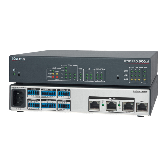
Page 21: Front Panel Features
Front Panel Features This section shows front panel features and their locations. The quantity and location of ports and corresponding front panel LEDs differ among IPCP models. However, the functions of each type of port and their LEDs are identical for all models. Aside from a few features of the IPCP Pro PCS1 xi, most of the features and LED Ports, Addressing, and Connections indications are described and shown in the section starting on page 21... - Page 22 IPCP Pro 355DRQ xi Front Panel IR Receiver Tx Rx RTS CTS Tx Rx Tx Rx 1 2 3 4 G +V +S -S G IR Learning Angle PWR OUT = 6W eBUS COM 1 COM 2 COM 3 DIGITAL I/O and Distance Power 15˚...
- Page 23 IPCP Pro 355MQ xi (within another device) eBUS RELAYS IR/S LINK LIMIT BUSY ERROR OVER eBUS Digital Relay eBUS Digital Relay LEDs (Serial) Serial LEDs LEDs (Serial) Serial LEDs LEDs LEDs LEDs LEDs LEDs LEDs IPCP Pro 360MQ xi (within another device) IPCP PRO 255Q xi PoE+ IR/S...
- Page 24 eBUS COM (Serial) Digital I/O IR/Serial LEDs LEDs LEDs IPCP PRO PCS1 xi POWER eBUS I/O IR/S LAN/ 1000 LIMIT Power Network LINK BREAKER LEDs OVER Reset Button AC Power Button Circuit and LED Breaker (recessed) Figure 11. IPCP Pro PCS1 xi Front Panel FOX3 MATRIX CONTROL IPCP PRO Q xi CONTROL AV LAN...
-
Page 25: Ipcp Pro Pcs1 Xi-Specific Front Panel Features
IPCP Pro PCS1 xi-Specific Front Panel Features Power button (switch) and LED POWER The front panel power button (switch) provides a way to manually turn switched AC power output on or off for the rear panel AC power output cable on the IPCP Pro PCS1 xi. NOTE: The button is not a safety disconnect device. -
Page 26: Ir Learning Receiver
IR Learning Receiver In most cases, Extron has already produced a driver file for controlling the projector, display, or source device you plan to use. If a device driver file is not available, you can create your own using Extron IR Learner Pro software, the remote control of the projector or display, and the IR learning receiver sensor on many models of IPCPs. -
Page 27: Ul Rack Mounting Guidelines
UL Rack Mounting Guidelines The following Underwriters Laboratories (UL) guidelines pertain to the safe installation of IPCP Pro xi Series control processors in a rack. CAUTION: • Elevated operating ambient temperature — If installed in a closed or multi-unit rack assembly, the operating ambient temperature of the rack environment may be greater than room ambient temperature. -
Page 28: Rear Panel Features Of The Din Rail Model
Rear Panel Features of the DIN Rail Model Mounting Slot Side View Rear View Mounting Mounting Clip Clip Figure 13. IPCP Pro 355DRQ xi Rear Panel Features Mounting an IPCP DIN Rail Unit to a DIN Rail To fasten the IPCP Pro 355DRQ xi to a DIN rail: Side View Figure 14. -
Page 29: Mounting The Ipcp Pro Matrix Q Xi Into A Matrix Switcher
Figure 15. The IPCP Pro 355DRQ xi Mounted on a DIN Rail, Before Cabling Mounting the IPCP Pro Matrix Q xi Into a Matrix Switcher The IPCP Pro Matrix Q xi mounts within an Extron FOX3 matrix switcher using the captive screws ( figure 19 on page 25). -
Page 30: Rear Panels - Rack Mount Models Without Av Lan
Rear Panels — Rack Mount Models Without AV LAN E E E E E E E D D D D D D D I I I I I I I IPCP Pro 250 xi IPCP Pro S1 xi COM 1 COM 2 DIGITAL I/O IPCP PRO S1 xi... -
Page 31: Rear Panels - Rack Mount Models With Av Lan
Rear Panels — Rack Mount Models E E E E E E E D D D D D D D I I I I I I I IPCP Pro 355MQ xi With AV LAN (within another device) COM 1 COM 2 COM 3 DIGITAL I/O AV LAN 2 AV LAN 3... -
Page 32: Front Panel - Din Rail Model
Front Panel — DIN Rail Model E E E E E E E D D D D D D D I I I I I I I J J J J J J J IPCP Pro 355DRQ xi Front Panel Tx Rx RTS CTS Tx Rx... -
Page 33: Rear Panel - Ipcp Pro Fox3 Matrix Q Xi
Rear Panel — IPCP Pro FOX3 Matrix Q xi IPCP IPCP Matrix AV LAN M M M M M M M M M IPCP Pro FOX3 Matrix Q xi FOX3 MATRIX CONTROL 00-05-A6-XX-XX-XX 00-05-A6-XX-XX-XX MAC: 00-05-A6-XX-XX-XX MATRIX MAC: 00-05-A6-XX-XX-XX IPCP LAN IPCP PRO Q xi CONTROL S/N: ####### E###### 00-05-A6-XX-XX-XX... -
Page 34: Power Connections
Power Connections Power for the IPCP Pro FOX3 Matrix Q xi is provided by the FOX3 matrix switcher into which it is installed (see Mounting the IPCP Pro Matrix Q xi Into a Matrix Switcher on page 9). For all other models, follow cabling directions in this section. - Page 35 Power input connector (internal power supply) — Connect the IPCP to a 100 to 240 VAC power source here (see figure 16 on page 22 or figure 17 on page 23). 100-240V 50-60Hz Power Input, Internal Power Supply • Connect to 100 to •...
- Page 36 Switched 12 VDC power output ports — These ports (see figure on page 22) provide 12 VDC output. For the IPCP Pro 550 xi and IPCP Pro 555Q xi, the four ports provide up to a combined maximum of 40 watts. Once configured, each port can be separately turned on or off.
- Page 37 • Veillez à toujours utiliser le câble d’alimentation fourni avec l’unité. • Should you need to use a different power cord, consult Extron Electronics prior to using the cord. • Si vous devez utiliser un autre câble d’alimentation, contactez Extron Electronics avant d’utiliser ce câble.
-
Page 38: Bidirectional Control And Communication Connections And Features
Bidirectional Control and Communication Connections and Features 3-pole COM ports, RS-232 only (see figure figure 17, and figure 18 on page 22 through page 24) 5-pole COM ports, RS-232/RS-422/RS-485 — Use COM ports for serial control of a display or other device and to receive status messages from the connected devices. - Page 39 LAN (Ethernet) connectors and LEDs (Ethernet) (see figure figure 17, and figure 18 on page 22 through page 24) and AV LAN connectors and LEDs (Ethernet) — To connect the IPCP to an Ethernet network (for configuration and control of the IPCP and the devices connected to it), plug a cable into one of these RJ-45 sockets and connect the other end of the cable to a network switch, hub, router, or PC connected to a local network or the Internet.
- Page 40 Network Port Addressing: If you use static IP addresses, configure the settings and IP addresses via Toolbelt. See the help file for Global Configurator or Toolbelt for basic information on configuration. PCS software version 4.5 or higher can also be used to set IP addresses on units with AV LAN ports as long as the ports are set to the default addresses.
- Page 41 For models without AV LAN: Connect the PC that you will use for setup, the LAN port of the control processor, and the touchpanels to the same Ethernet network. Ethernet TCP/IP Network NOTE: IPCPs with more than one LAN port Insert Twisted function as multiport, unmanaged Pair Wires...
- Page 42 Network Ethernet Insert Twisted Network Pair Wires AV LAN (Ethernet) Default protocol, AV LAN: • IP address: Ethernet 192.168.254.250 • Subnet mask: 255.255.255.0 • DNS address: 127.0.0.1 Front Panels, Rear Panels, Rack Mount • DHCP server off (disabled) Rack Mount Models Models •...
-
Page 43: Unidirectional Control And Communication Connections
Unidirectional Control and Communication Connections IR/Serial output ports (see figure figure 17, and figure 18 on page 22 through page 24) — An IPCP Pro xi Series control processor can use infrared signals or unidirectional RS-232 serial signals to control various devices (up to four per port for IR) via these ports. Set output signal type (IR or serial) during configuration. - Page 44 Relay ports — Relay ports (see figure figure 17, and figure 18 on page 22 through page 24) provide control for power, screen or projector lifts, window coverings, and similar items, when trigger events occur. All relays normally open. Front Panels, Front/Bottom Panel, Rear Panels, Rack Mount Models Relays...
-
Page 45: Additional Control Ports
Additional Control Ports Flex I/O ports (see (figure 16 figure 17 on page 22 and on page 23) — To allow the IPCP Pro xi Series control processor to monitor devices to trigger events, connect switches, sensors, LEDs, relays, or similar items to these ports. - Page 46 • Example application, analog input with pull-up: adjusting audio levels using a 10k potentiometer In this example, the flex I/O port is configured for analog input, and it supplies a pull-up voltage to the potentiometer. The position of the 10k potentiometer determines the voltage that this port provides, ranging from 0 VDC to 4.15 VDC.
- Page 47 Digital input — To allow the IPCP to monitor external devices that do not use RS-232 communication, connect a switch, motion sensor, moisture sensor, tally feedback output, button pad, relay contact, or a similar item to a Flex I/O port, and configure it for digital input. When configured as a digital input, the port is set to measure two states: high and low.
- Page 48 • Flex I/O digital input with pull-up enabled: • When the port is configured for pull-up, switch 2 is closed, activating the +5.0 VDC pull-up resistor. • An external short to ground creates a logic low. • An open circuit creates a logic high •...
- Page 49 • Flex I/O digital output with pull-up disabled: • When switch 1 closes, the port is on and the front panel LED is on. • When switch 1 opens, the port is off and the front panel LED is off. •...
- Page 50 • Flex I/O digital output with pull-up enabled: • When the port is configured for pull-up, switch 2 is closed, activating the +5.0 VDC pull-up resistor. • When switch 1 closes, the port is on and the front panel LED is on. •...
- Page 51 Digital I/O (digital input/output) ports — These ports work the same way the flex I/O ports work, but they do not offer analog input, and thresholds are not adjustable. Connect physical switches, sensors, LEDs, relays, or similar items to these ports (see figure figure 17, and...
- Page 52 • Digital I/O digital input with pull-up disabled: • Digital input is triggered by an external switch or voltage between the digital input pin and ground. • Example application, digital input without pull-up: occupancy sensor connection: +5.0 V 1k ohms SW 2 Occupancy Sensor...
- Page 53 Digital output — To activate LEDs, incandescent lights, or other devices that accept a TTL signal, or to provide contact closure control for projector lifts, motorized screens, room or light switches via an Extron IPA T RLY4 or similar device, you can use one or more of these ports as a digital output. When a port is configured for digital output, it offers two output states: on and off.
- Page 54 To determine the value of the current limiting resistor in the circuit shown above, you need to know the values of three variables: i = LED forward current in amps (found in the data sheet for the LED) = LED forward voltage drop in volts (found in the data sheet for the LED) = supply voltage of the external voltage source Insert those values into the following equation to determine the resistor value: Example calculation:...
- Page 55 eBUS port (see figure figure 17, and figure 18 on page 22 to page 24) — eBUS is a technology (proprietary bus architecture and serial communication protocol) developed by Extron. It allows many eBUS devices (such as button panels) and accessories (including power and signal hubs) to be connected to a single control processor to expand the capabilities of a control system.
- Page 56 This port provides power to eBUS devices. If the power draw by the connected devices reaches the maximum level allowed, the eBUS Limit LED lights. If the power consumption exceeds the allowed threshold, the IPCP shuts off the eBUS port and lights the eBUS Overload (Over) LED. If that occurs, you must resolve the hardware cause of the power overload before the IPCP can successfully restore function to this port.
- Page 57 Volume control port — To provide volume control for some Extron half rack audio amplifiers (such as the XPA and MPA models listed in figure 19), connect this port (see figure 16 on page 22 and figure 17 page 23) to the volume remote control port on the amplifier as shown below. Configure the maximum and minimum voltage limits.
-
Page 58: Resetting The Unit
Resetting the Unit There are six reset modes that are available by pressing the Reset button on the front panel (for most models) or the rear panel (for the IPCP Pro xi embedded control processors). Reset button is recessed, so use a pointed stylus, ballpoint pen, or Extron Tweeker to access it. - Page 59 IPCP Pro Q xi and xi Series Control Processor Reset Mode Summary Use This Activation Result Mode to... Recover To start the Project Recovery reset mode and recover a project: Project Recovery mode stops regular project operation and allows a connection to be 1.
- Page 60 IPCP Pro Q xi and xi Series Control Processor Reset Mode Summary Use This Activation Result Mode to... Reset All Network Settings mode: Reset IP To reset all network settings: settings and 1. Press and hold the Reset button until the Power LED blinks Turns DHCP off (for LAN ports).
-
Page 61: Software-Based Configuration And Control
Software-Based Configuration and Control This section of the guide is divided into the following topics: • Configuration and Control: An Overview • Basic Setup Steps: a Guide to this Section and Other Resources • Downloading the Software and Getting Started •... -
Page 62: Basic Setup Steps: A Guide To This Section And Other Resources
Basic Setup Steps: a Guide to this Section and Other Resources NOTE: GC projects can be created offline and uploaded to the hardware at a later date. Follow the steps in Setup Checklist: How to Proceed With Installation starting on page 9. The overall process for setting up a control processor using GC is as follows: Within Global Configurator Configure the IP settings... -
Page 63: Downloading The Software And Getting Started
Downloading the Software and Getting Started Download GC software updates and a large variety of device drivers can be downloaded from the page on the Extron website (www.extron.com/download/index.aspx). When you locate the desired software or driver package, follow the on-screen directions to download and install it. NOTE: New RS-232 and Ethernet drivers are required. -
Page 64: Obtaining Control Drivers
2. For software, click on the link for the specific software that you need. A software product page opens that provides a description of the software package, a list of system requirements, a list of features, and access to the release notes, in addition to a download link. For drivers: Control System Drivers a. -
Page 65: Things To Do After Installing Gc And Before Starting A Project
Things to Do After Installing GC and Before Starting a Project • Read the Global Configurator Help File, included with the software, for details and step-by-step procedures on how to start a GC Professional or GC Plus project and perform basic setup tasks for a control processor. The help file provides a wealth of information on settings and how to use the software. -
Page 66: Power Connections
Power Connections • Ensure that all devices are plugged in. • Make sure that each device is receiving power. The IPCP front panel power LED lights if the IPCP is receiving power. • If the IPCP includes switched power output ports, verify that the overload indicator LED is not lit. If the switched 12 VDC power output Over LED is lit, the power draw at the switched power ports has been exceeded. -
Page 67: Device Control Connections And Configuration
Device Control Connections and Configuration • Verify that ports are wired correctly and that ground (earthing) wires are connected to the proper pins on the control processor and, if applicable, on the controlled device. • Ensure that each IR emitter head is placed adjacent to or directly over the IR pickup window on the controlled device. -
Page 68: Reference Information
Reference Information This section of the guide includes the following reference items: • Network Port Requirements and Licensed Third-Party Software • File Types: a Key to Extron-specific File Names • Secure Sockets Layer (SSL) Certificates • IEEE 802.1X Certificates • SNMP •... -
Page 69: Secure Sockets Layer (Ssl) Certificates
Secure Sockets Layer (SSL) Certificates Extron control processors ship with factory-installed SSL certificates created by Extron. If you want or are required to use a different SSL certificate at your installation site, then you can use system utilities in the Toolbelt software to change the SSL certificate at any time. -
Page 70: Ieee 802.1X Certificates
IEEE 802.1X Certificates IEEE 802.1X is a standard that enables port-based network access control via an authentication server. The protocol requires that all devices must be authenticated before gaining privileges to access the secure part of the network. The Extron implementation of 802.1X supports PEAP - MSCHAPV2 and EAP - TLS methods of authentication. This section of the guide details the requirements for any certificate file (machine or CA) (below) and the private key file (for the machine certificate) to be used in the system. -
Page 71: Snmp
SNMP Extron control products support Simple Network Management Protocol (SNMP). SNMP facilitates the exchange of basic network management information between network devices. It helps in monitoring of operations and factors such as packet usage, memory usage, remote password resets, and collection of error information. An information technology administrator can use common IT tools to monitor those factors, as well as look up device location and the name of the contact person for the device. -
Page 72: Unmounting A Din Rail Unit
Unmounting a DIN Rail Unit If the need arises, the IPCP Pro 355DRQ xi can be removed from the DIN rail, whether or not cables are still attached. Remove or unmount the unit as follows: 1. Pull the mounting clip down to release the unit from the bottom of the rail (see figure 46, ). -
Page 73: Firmware Updates
Firmware Updates If the need arises, you can replace the IPCP firmware. This section covers the following firmware-related topics: • Determining the Firmware Version • Updating the Firmware Determining the Firmware Version There are several ways to check which firmware version the control processor is using: •... -
Page 74: Locating And Downloading The Firmware
Locating and Downloading the Firmware 1. Visit the Extron website to find the latest firmware file for the control processor. The easiest way to locate files is through the Downloads tab on the web page for the specific model. .exe 2. -
Page 75: Extron Warranty
Electronics makes no further warranties either expressed or implied with respect to the product and its quality, performance, merchantability, or fitness for any particular use. In no event will Extron Electronics be liable for direct, indirect, or consequential damages resulting from any defect in this product even if Extron Electronics has been advised of such damage.
Need help?
Do you have a question about the IPCP Pro Q xi Series and is the answer not in the manual?
Questions and answers