
Related Manuals for Extron electronics IPCP 505


Summary of Contents for Extron electronics IPCP 505
- Page 1 User Guide IP Link Products ® IPCP 505 IP Link Control Processor 68-2026-01 Rev. C 03 20...
- Page 2 Safety Instructions Safety Instructions • English Istruzioni di sicurezza • Italiano AVVERTENZA: Il simbolo, , se usato sul prodotto, serve ad WARNING: This symbol, ,when used on the product, is avvertire l’utente della presenza di tensione non isolata pericolosa intended to alert the user of the presence of uninsulated dangerous all’interno del contenitore del prodotto che può...
- Page 3 , and trademarks are the property of RGB Systems, Inc. or (®) (SM) (™) Extron Electronics (see the current list of trademarks on the Terms of Use page at www.extron.com): Registered Trademarks (®) Extron, Cable Cubby, ControlScript, CrossPoint, DTP, eBUS, EDID Manager, EDID Minder, Flat Field, FlexOS, Glitch Free, Global Configurator, Global Scripter, GlobalViewer, Hideaway, HyperLane, IP Intercom, IP Link, Key Minder, LinkLicense, LockIt, MediaLink, MediaPort, NetPA,...
- Page 4 FCC Class A Notice This equipment has been tested and found to comply with the limits for a Class A digital device, pursuant to part 15 of the FCC rules. The Class A limits provide reasonable protection against harmful interference when the equipment is operated in a commercial environment.
- Page 5 Conventions Used in this Guide Notifications The following notifications are used in this guide: ATTENTION: • Risk of property damage. • Risque de dommages matériels. NOTE: A note draws attention to important information. TIP: A tip provides a suggestion to make working with the application easier. Software Commands Commands are written in the fonts shown here: ^AR Merge Scene,,Op1 scene 1,1 ^B 51 ^W^C...
-
Page 7: Table Of Contents
Customizing the IPCP Control Web Pages ..51 Connections ..........15 Troubleshooting ..........52 Additional Control Ports ........ 17 Power Connections ........52 Resetting the Unit ..........18 Data Connections ......... 52 Device Control Connections and Configuration ..........52 IPCP 505 • Contents... - Page 8 Symbol Definitions ........56 Updating Firmware via Command/Response Table for Extron Firmware Loader Software ....88 SIS Commands ........... 61 Reference Information ....... 79 Glossary ............79 File Types: a Key to Extron-specific File Names ............80 IPCP 505 • Contents viii...
-
Page 9: Introduction
Important Information You Need Before Installation The order and types of setup tasks for the IPCP 505 control processor and TouchLink touchpanels are important. Pay close attention to them. Follow the setup checklist in the Hardware Features and Installation on page 8. IPCP 505 • Introduction... -
Page 10: About The Ipcp 505
100-240 VAC, 50-60 Hz input. Feature summary table The following table provides a summary of major features. Features Ports Power Switched 3-pole 5-pole Flex Mounting Supply 12 VDC Out Serial Relay Learning Rack Internal IPCP 505 • Introduction... -
Page 11: Controlling Other Devices
Blu-ray™ players. Users can create their own device drivers (IR) or go to the Extron website (www.extron.com) to obtain device drivers. The IPCP also provides four independently switched 12 VDC outputs, and can control up to eight Ethernet-enabled AV devices. IPCP 505 • Introduction... -
Page 12: Application Diagrams
1365x1024 1080p Switcher Extron DVD 1 Extron IR Emitter MVC 121 RS-232 Mixer/volume DVD 2 Screen Controller 2 MIC 1 MIC 2 MAIN 3 MASTER MVC 121 Controller MIXER/VOLUME CONTROLLER Figure 3. A Typical IPCP 505 Application IPCP 505 • Introduction... -
Page 13: Ir And Rs-232 Device Control
Extron. See the Global Configurator Help File or the IR Learner Help File (which come with the software) for details on setting up the IPCP and for downloading, programming, or learning device control commands. IPCP 505 • Introduction... -
Page 14: How The Ipcp 505 Works: Components And Interactions
Switch, LED, or Relay Figure 5. How the IPCP 505 Works The IPCP can be configured completely via Global Configurator software. Once you have set up how you want it to work (assigned drivers to ports, configured relays and contact closure input, and set up IP addresses and functions), that information is saved to a project file that is uploaded into the IPCP. -
Page 15: System Requirements
4.0 or higher Browser Microsoft Internet Explorer ® version 6.0 or higher with ActiveX enabled ® NOTE: GUI Configurator is used to set up any Extron TouchLink touchpanel that will be used with the IPCP. IPCP 505 • Introduction... -
Page 16: Hardware Features And Installation
Connect any Extron TLP touchpanels that will be part of the system to the same network as the PC and IPCP. Create a user interface layout for the touchpanels and upload the GUI configuration to each touchpanel. See the GUI Configurator Help File for instructions. IPCP 505 • Hardware Features and Installation... - Page 17 … Create a display disconnection notification e-mail. … Perform configurations for special applications, if needed. … Save the Global Configurator project/configuration. … Build and upload the configuration. … Test the system. IPCP 505 • Hardware Features and Installation...
-
Page 18: Front Panel Features
Ethernet connection settings to be reset to the factory defaults. The green LED flashes depending on the selected reset mode (see Resetting the Unit and the reset modes table on page 18 for details). IPCP 505 • Hardware Features and Installation... -
Page 19: Mounting The Ipcp 505
Reliable earthing (grounding) — Maintain reliable grounding of rack-mounted equipment. Pay particular attention to supply connections other than direct connections to the branch circuit (such as use of power strips). IPCP 505 • Hardware Features and Installation... -
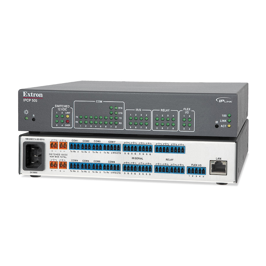
Page 20: Rear Panel Features And Connections
If the ports are disabled, the user must disconnect or fix the attached devices to correct the problem, after which power output can be re-enabled via controls in the IPCP internal web pages or via an SIS command. IPCP 505 • Hardware Features and Installation... -
Page 21: Bidirectional Control And Communication Connections And Features
In some cases the IPCP may be capable of transmitting and controlling a given device via RS-232 up to 250 feet (76 m) away, but the RS-232 response levels of that device may be too low for the IPCP to detect. IPCP 505 • Hardware Features and Installation... - Page 22 Use a crossover cable for connection directly to a PC. Wire the connector as shown in the tables above. MAC address — This is the unique user hardware ID number (MAC address) of the unit (for example, 00-05-A6-05-1C-A0). You may need this address during configuration. IPCP 505 • Hardware Features and Installation...
-
Page 23: Unidirectional Control And Communication Connections
One Single IR Emitter Dual IR Emitter Installing Two Single Emitters When installing only single emitters, tie them in series as shown below. Ground (−) (−) IR Signal (+) (−) Two Single IR Emitters IPCP 505 • Hardware Features and Installation... - Page 24 Configurator software or SIS commands to change the length of the timeout period. See the variable on page 67 and the corresponding relay port commands SIS Programming and Control page 66 in the section for details. IPCP 505 • Hardware Features and Installation...
-
Page 25: Additional Control Ports
Ground Share the same ground among Wire I/O connections. Device 4 Switch, (Switches, sensors, Device 3 Sensor LEDs, relays, or Device 2 similar items) Device 1 Figure 13. Flex I/O Port Wiring Examples IPCP 505 • Hardware Features and Installation... -
Page 26: Resetting The Unit
Modes 3 through 5. For Mode 5 (Reset to Factory Defaults) the LED blinks three times, the third blink indicating the last mode. The modes are separate functions, not a continuation from Mode 1 to Mode 5. IPCP 505 • Hardware Features and Installation... - Page 27 • The factory configured password for this device has been set to the device serial number. Passwords are case sensitive. Performing a Reset to Factory Defaults reset sets the password to no password. IPCP 505 • Hardware Features and Installation...
-
Page 28: Software-Based Configuration And Control
The third way to control and configure the controller is by using Simple Instruction Set (SIS) commands via Telnet (or a similar program), a web browser, or RS-232. SIS commands are discussed in detail in SIS Programming and Control starting on page 53. IPCP 505 • Software-based Configuration and Control... -
Page 29: Basic Setup Steps: A Guide To This Section And Other Resources
IP settings of the PC in order to communicate with the controller (see Setting up the PC for IP Communication With an IPCP 505 page 25). Then you must change the default IP address, subnet mask, and [optional] administrator name and password of the controller in order to use the IPCP on a network. -
Page 30: Configuring The Ipcp For Network Use Via Global Configurator
Figure 14. Sending the arp –s Command After the arp -s command is issued, the controller changes to the new address and starts responding to the ping requests, as described in the next step. IPCP 505 • Software-based Configuration and Control... - Page 31 Optional step: after verifying that the IP address change was successful, enter and issue the arp –d command at the prompt. For example: arp –d 192.168.197.7 removes 192.168.197.7 from the ARP table arp –d* removes all static IP addresses from the ARP table. IPCP 505 • Software-based Configuration and Control...
-
Page 32: Configuring The Ipcp For Network Use Via A Browser
Once the IP address of the controller is changed, you lose communication with the controller. Close the browser. After changing the IP settings of the controller, change the TCP/IP settings of the PC back to their original configuration. IPCP 505 • Software-based Configuration and Control... -
Page 33: Configuring The Ipcp For Network Use Via Sis Commands And Telnet
IP address for the controller or confirm whether you need to set up the IPCP 505 for DHCP (Dynamic Host Configuration Protocol) to have an address assigned automatically when you sign on. IPCP 505 • Software-based Configuration and Control... - Page 34 • For Windows XP, right-click on Local Area Connection, then select Properties. • For Windows 7, click on Local Area Connection to open the Local Area Connection Status dialog box, then click Properties. IPCP 505 • Software-based Configuration and Control...
- Page 35 Write down the current IP address and subnet mask of the PC below. If your PC is set to “Obtain an IP address automatically,” make a note of that, instead. You will need to restore these settings to the PC later. IP address: Subnet mask: IPCP 505 • Software-based Configuration and Control...
- Page 36 Restore the previous IP configuration of the PC by following steps 1, 2, 3, and 5, but use the original IP address settings for the PC that you wrote down in step 4. IPCP 505 • Software-based Configuration and Control...
-
Page 37: Global Configurator Software For Windows
Obtain this information from your network administrator and set the IP address before continuing. PC System Requirements System Requirements on page 7 for the minimum hardware and software requirements. NOTE: The IPCP 505 requires GC version 3.2 or higher. IPCP 505 • Software-based Configuration and Control... -
Page 38: Using Global Configurator: Helpful Tips
Valid characters are A-Z, a-z, 0-9, and - (hyphen). The name cannot start with a number or a hyphen, and it cannot end with a • hyphen. • Maximum name length is 24 characters. IPCP 505 • Software-based Configuration and Control... -
Page 39: Advanced Configuration
IR remote for the device so that it faces the IR learning receiver (on the IPCP front panel) within the angles and distance range shown in the front panel diagram on page 10. IPCP 505 • Software-based Configuration and Control... -
Page 40: Printing A Wiring Block Diagram Or A Gui Configuration Report
See the Firmware Updates section starting on page 81 for instructions on how to update the firmware for the controller. NOTE: Save the existing GC configuration project before replacing the firmware. IPCP 505 • Software-based Configuration and Control... -
Page 41: Advanced Serial Port Control
IPCP (unit 1) PC or Display RS-232 Ethernet TCP/IP Ethernet RS-232 Third Party or Other (serial) (serial) Network port port Device port port AV Device Figure 20. Methods of Advanced Serial Port Control IPCP 505 • Software-based Configuration and Control... - Page 42 SIS commands (see page 72) to assign a different range of port numbers to these ports, if needed. An IR/serial port must be configured for serial communication to be used for direct port access. IPCP 505 • Software-based Configuration and Control...
- Page 43 COM ports on the IPCP. To use serial bridging, two IPCP or IPL devices (one local and one remote) must be enabled to communicate with each other, establishing PC, touchpanel, or controller access to a remote AV device. IPCP 505 • Software-based Configuration and Control...
- Page 44 Enter the IP address of unit 2 in the browser Address field at the top of the screen, and press the <Enter> key. The System Status page opens, showing the current IP and serial port settings of unit 2. IPCP 505 • Software-based Configuration and Control...
- Page 45 Serial Bridging System Diagram and Port Numbers Click the Submit button (see figure 24, ). The AV device attached to remote unit 1 should now accept all serial commands from your PC, touchpanel, or controller. IPCP 505 • Software-based Configuration and Control...
-
Page 46: Saving And Uploading The Configuration
• Administrators have access to all of the web pages and are able to make changes to settings. Users can access the System Status page only. IPCP 505 • Software-based Configuration and Control... - Page 47 The Status web page provides only settings information. Changes must be made via the Configuration web page, the Global Configurator software, or SIS programming. Personnel who have user access can view the Status page but do not have access to configuration pages. IPCP 505 • Software-based Configuration and Control...
- Page 48 The System Status page provides information about the IPCP 505 model, part number, firmware version, port and IP settings, as shown in the following example. This information is useful when troubleshooting. Figure 26. A System Status Embedded Web Page IPCP 505 • Software-based Configuration and Control...
- Page 49 Spaces ( ) and underscores (_) are not permitted within the name of an IPCP unit. Valid characters are A-Z, a-z, 0-9, and - (hyphen). • • The name cannot start with a number or hyphen. It cannot end with a hyphen. IPCP 505 • Software-based Configuration and Control...
- Page 50 It also permits control and grouping of the switched 12 VDC power output ports. Click Configuration (see figure 28, ) and Port Settings ( ) to open the page. Figure 28. A Port Settings Embedded Web Page IPCP 505 • Software-based Configuration and Control...
- Page 51 Clicking on a port and then a command name makes the IPCP send that command out its linked IR port to the connected device. Figure 29. An IR Drivers Embedded Web Page IPCP 505 • Software-based Configuration and Control...
- Page 52 In this page you can specify the IP address and domain name of the web server, set up SMTP verification credentials, and specify the addresses of e-mail alert recipients and which e-mail file they will be sent. Figure 31. An Email Alerts Embedded Web Page IPCP 505 • Software-based Configuration and Control...
- Page 53 Figure 32. A Firmware Upgrade Embedded Web Page NOTES: • Firmware Updates starting on page 81 for instructions on how to update the firmware. Save the existing configuration project before replacing the firmware. • IPCP 505 • Software-based Configuration and Control...
- Page 54 They are necessary for operation of the controller. Never delete the main event file (0.evt). Les fichiers Événement (__.evt) NE doivent PAS être supprimés. Ils sont nécessaires • au fonctionnement du contrôleur. Ne jamais supprimer le fichier Événement principal (0.evt). IPCP 505 • Software-based Configuration and Control...
-
Page 55: Globalviewer Web Pages
GC. The Info screen appears for the overall system, not for specific connected devices. Read the Global Configurator Help File for details about each screen and how to use the GlobalViewer pages. IPCP 505 • Software-based Configuration and Control... - Page 56 The following figures are examples of IPCP 505 GlobalViewer pages. Figure 35. GlobalViewer Schedule Page Figure 36. GlobalViewer Monitor Page IPCP 505 • Software-based Configuration and Control...
- Page 57 The following figure shows an example. Figure 38. A GlobalViewer Overall System Device Control Page You can click the GlobalViewer on-screen buttons in the Control pages to send the corresponding command from the IPCP to that device. IPCP 505 • Software-based Configuration and Control...
-
Page 58: Controlling The Ipcp 505 With A Touchpanel
IPCP or the network and use just the touchpanels to control the IPCP. • If the system components do not respond properly when you test the touchpanel, check and adjust the configuration of the IPCP using GC, then upload the revised configuration. IPCP 505 • Software-based Configuration and Control... -
Page 59: Customizing The Ipcp Control Web Pages
Your choice of labels for panel buttons A company or institution logo • Visit the Extron website (http://www.extron.com/product/customgui.aspx) or contact an Extron customer support representative for more information on this service and on available template options. IPCP 505 • Software-based Configuration and Control... -
Page 60: Troubleshooting
(IR or RS-232) are associated with the correct ports on the IPCP and on the other devices. If you still experience problems, call the Extron Sales & Technical Support Hotline or the Extron S3 Control Systems Support Hotline (1.800.633.9877). IPCP 505 • Software-based Configuration and Control... -
Page 61: Sis Programming And Control
IPCP responds by sending a message to the host. No response is required from the host. The IPCP-initiated messages are listed here. (c) Copyright 2013, Extron Electronics, IPCP 505, Vx.xx, 60-1071-02 ] Day, DD MMM YYYY HH:MM:SS ] Vx.xx is the firmware version number. -
Page 62: Password Information
(port 80) connection using URL-encoded commands. The ASCII and URL commands listed in the tables starting on page 61 perform the same functions, but they are encoded differently to accommodate the requirements of each port (Telnet or browser). IPCP 505 • SIS Programming and Control... -
Page 63: Entering Sis Commands: Helpful Tips
NOTE: With Telnet you can use either an “Escape” ( E ) command or a “W” command, and the carriage return or the pipe character. With the web browser, you are required to use a “W” command and the pipe character. IPCP 505 • SIS Programming and Control... -
Page 64: Symbol Definitions
Example: Tue, 13 Jun 2011 18:19:33 IP address (xxx.xxx.xxx.xxx). Leading zeros in each of the four fields are optional in setting values, and they are suppressed in returned values.IPCP 505 default address: 192.168.254.254. E-mail domain name; for example, extron.com IPCP 505 • SIS Programming and Control... - Page 65 Ipn• rather than just the data X1@ ] Priority status for receiving timeouts: 0 = use send data string command parameters (0 = default) 1 = use configure receive timeout command parameters IPCP 505 • SIS Programming and Control...
- Page 66 ), itself, is the response. When the connection is via IP, is 4 asterisks (****) if a password has been assigned, or it is an empty field ( ) if a password hasn’t been assigned. IPCP 505 • SIS Programming and Control...
- Page 67 (****). a “0”) for digital inputs: 0 - 04095 (0 - 25.3 VDC) 164 = default ≈ 1 VDC. NOTE: The lower threshold ( ) must be smaller than the upper threshold ( IPCP 505 • SIS Programming and Control...
- Page 68 1 = RS-232 port (±5 VDC) NOTE: For commands and examples of computer or device responses mentioned in this guide, the character “0” is used for the number zero and “O” represents the capital letter “o”. IPCP 505 • SIS Programming and Control...
-
Page 69: Command/Response Table For Sis Commands
IPCP 505 • SIS Programming and Control... - Page 70 IPCP 505 • SIS Programming and Control...
- Page 71 IPCP 505 • SIS Programming and Control...
- Page 72 IPCP 505 • SIS Programming and Control...
- Page 73 IPCP 505 • SIS Programming and Control...
- Page 74 IPCP 505 • SIS Programming and Control...
- Page 75 IPCP 505 • SIS Programming and Control...
- Page 76 IPCP 505 • SIS Programming and Control...
- Page 77 IPCP 505 • SIS Programming and Control...
- Page 78 IPCP 505 • SIS Programming and Control...
- Page 79 IPCP 505 • SIS Programming and Control...
- Page 80 IPCP 505 • SIS Programming and Control...
- Page 81 IPCP 505 • SIS Programming and Control...
- Page 82 IPCP 505 • SIS Programming and Control...
- Page 83 IPCP 505 • SIS Programming and Control...
- Page 84 IPCP 505 • SIS Programming and Control...
- Page 85 IPCP 505 • SIS Programming and Control...
- Page 86 IPCP 505 • SIS Programming and Control...
-
Page 87: Reference Information
Glossary • • File Types: a Key to Extron-specific File Names Full product specifications are available via the IPCP 505 product page at www.extron.com. Glossary Custom web page Any file that can be loaded into an IPCP and served by the internal web server. The IPCP can be used for various web-based tasks. -
Page 88: File Types: A Key To Extron-Specific File Names
Firmware cannot be updated by loading an .s19 file through the File Management page, but it can be updated via the Firmware Upgrade web page (see page 45). IPCP 505 • Reference Information... -
Page 89: Firmware Updates
Connect the controller to a PC via an Ethernet connection, or connect the controller and the PC to a network/LAN. For details see Hardware Features and Installation starting on page 8, Software-based Configuration and Control starting on page 20, and the IPCP 505 Setup Guide. Start a web browser program. IPCP 505 • Firmware Updates... - Page 90 To reach the factory default web pages on a controller that has been set up for GlobalViewer, enter http://<IP address>/nortxe_index.html into the address field of the browser, substituting the actual IP address for “<IP address>”. For example, http://192.168.196.42/nortxe_index.html. IPCP 505 • Firmware Updates...
- Page 91 Embedded Web Page If using GlobalViewer, click the Type button in the upper left of the GV page (see figure 45, , below), and click on the IPCP 505 folder ( ). The firmware version is listed in the Control window ( Figure 44.
-
Page 92: Updating The Main Firmware
IPL_T_Series_19_1364_50_vxx_xx.s19 where xx_xx is the version number (xx.xx) or IPLtvx.x.x.S19 where x.x.x indicates the version number. NOTE: The firmware update file must have a filename extension of .s19. If the file does not have that extension, it will not work properly. IPCP 505 • Firmware Updates... -
Page 93: Updating Firmware Via Extron Ip Link File Manager Software
IPCP after the firmware is updated. See command details on page 78 in the SIS section. Click on the Tools menu and select Firmware Update Manager (see the image at right). The Firmware Update Manager window appears. IPCP 505 • Firmware Updates... -
Page 94: Updating Firmware Via The Ipcp Embedded Web Page
IPCP controller. This method allows you to update one IPCP at a time via an IP connection. Download the .s19 firmware file. Launch a web browser on the connected PC and type the IP address of the controller in the address area. IPCP 505 • Firmware Updates... - Page 95 Selecting the New Firmware File for the Upgrade In the Choose File to Upload dialog box, locate and select the firmware file (*.s19) ) you downloaded to C:\Program Files\Extron\Firmware\IPCP_505\xx, and click the Open button ( ). The dialog box closes. IPCP 505 • Firmware Updates...
-
Page 96: Updating Firmware Via Extron Firmware Loader Software
Once the firmware is uploaded, the IPCP restarts events. Firmware Loader displays the new firmware version in the Firmware column. Close or exit Firmware Loader. Verify that the IPCP is connected to the network and is functioning as expected. IPCP 505 • Firmware Updates... - Page 97 Extron Electronics makes no further warranties either expressed or implied with respect to the product and its quality, performance, merchantability, or fitness for any particular use. In no event will Extron Electronics be liable for direct, indirect, or consequential damages resulting from any defect in this product even if Extron Electronics has been advised of such damage.
Need help?
Do you have a question about the IPCP 505 and is the answer not in the manual?
Questions and answers