Table of Contents
Advertisement
Quick Links
Advertisement
Chapters
Table of Contents

Related Manuals for maxon motor EPOS2 Module 36/2


Summary of Contents for maxon motor EPOS2 Module 36/2
- Page 1 EPOS2 Positioning Controller Hardware Reference Edition May 2017 Positioning Controller Hardware Reference Document ID: rel7050 maxon motor ag Brünigstrasse 220 P.O.Box 263 CH-6072 Sachseln Phone +41 41 666 15 00 Fax +41 41 666 16 50 www.maxonmotor.com...
- Page 2 ERMISSION TO COMMENCE NSTALLATION The EPOS2 Module 36/2 is considered as partly completed machinery according to EU directive 2006/ 42/EC, Article 2, Clause (g) and therefore is intended to be incorporated into or assembled with other machinery or other partly completed machinery or equipment.
-
Page 3: Table Of Contents
4.14 Status LEDs..........36 maxon motor control EPOS2 Positioning Controller Document ID: rel7050 EPOS2 Module 36/2 Hardware Reference Edition: May 2017 © 2017 maxon motor. Subject to change without prior notice. - Page 4 5.3.5 Wiring Example: Two Axes with RS232 to CAN Gateway..... . . 45 maxon motor control Document ID: rel7050 EPOS2 Positioning Controller Edition: May 2017 EPOS2 Module 36/2 Hardware Reference © 2017 maxon motor. Subject to change without prior notice.
-
Page 5: Table 1-1 Table
Use for other and/or additional purposes is not permitted. maxon motor, the manufacturer of the equip- ment described, does not assume any liability for loss or damage that may arise from any other and/or additional use than the intended purpose. - Page 6 Windows® © Microsoft Corporation, USA-Redmond, WA Table 1-3 Brand Names and Trademark Owners maxon motor control Document ID: rel7050 EPOS2 Positioning Controller Edition: May 2017 EPOS2 Module 36/2 Hardware Reference © 2017 maxon motor. Subject to change without prior notice.
- Page 7 The present document – including all parts thereof – is protected by copyright. Any use (including repro- duction, translation, microfilming and other means of electronic data processing) beyond the narrow restrictions of the copyright law without the prior approval of maxon motor ag, is not permitted and sub- ject to persecution under the applicable law.
- Page 8 • • p a g e i n t e n t i o n a l l y l e f t b l a n k • • maxon motor control Document ID: rel7050 EPOS2 Positioning Controller Edition: May 2017 EPOS2 Module 36/2 Hardware Reference © 2017 maxon motor. Subject to change without prior notice.
-
Page 9: Documentation Structure
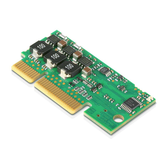
• wiring examples. maxon motor control’s EPOS2 Module 36/2 is a small-sized, full digital, smart motion controller. It is des- ignated for the use as plug-in module in customer-specific motherboards for single axis or multi axes motion control systems. Due to its flexible and high efficient power stage, the EPOS2 Module 36/2 drives brushed DC motors with digital encoder as well as brushless EC motors with digital Hall sensors and encoder. -
Page 10: Safety Precautions
– and be kept – in a safe operating mode. • Be aware that you are not entitled to perform any repair on components supplied by maxon motor. Best Practice •... -
Page 11: Electrical Data
Digital Output 5 (“High Speed Command”), push-pull Table 3-6 Electrical Data – Outputs maxon motor control 3-11 EPOS2 Positioning Controller Document ID: rel7050 EPOS2 Module 36/2 Hardware Reference Edition: May 2017 © 2017 maxon motor. Subject to change without prior notice. -
Page 12: Mechanical Data
Mounting with optional PCB support brackets Table 3-12 Mechanical Data maxon motor control 3-12 Document ID: rel7050 EPOS2 Positioning Controller Edition: May 2017 EPOS2 Module 36/2 Hardware Reference © 2017 maxon motor. Subject to change without prior notice. -
Page 13: Dimensional Drawings
Dimensional Drawing (with horizontal connector Meritec 983172-064-2MMF) [mm] ETAINER Figure 3-4 Footprint of Retainer (Meritec 983172-064-2MMF connector) [mm] maxon motor control 3-13 EPOS2 Positioning Controller Document ID: rel7050 EPOS2 Module 36/2 Hardware Reference Edition: May 2017 © 2017 maxon motor. Subject to change without prior notice. -
Page 14: Environmental Conditions
Accessories are not part of the delivery. You will need to order them separately. maxon motor control 3-14 Document ID: rel7050 EPOS2 Positioning Controller Edition: May 2017 EPOS2 Module 36/2 Hardware Reference © 2017 maxon motor. Subject to change without prior notice. -
Page 15: Standards
Mean Time Between Failures (MTBF): 610'435 hours Table 3-16 Standards maxon motor control 3-15 EPOS2 Positioning Controller Document ID: rel7050 EPOS2 Module 36/2 Hardware Reference Edition: May 2017 © 2017 maxon motor. Subject to change without prior notice. - Page 16 • • p a g e i n t e n t i o n a l l y l e f t b l a n k • • maxon motor control 3-16 Document ID: rel7050 EPOS2 Positioning Controller Edition: May 2017 EPOS2 Module 36/2 Hardware Reference © 2017 maxon motor. Subject to change without prior notice.
-
Page 17: Pin Assignment
EPOS RS232 receive EPOS TxD EPOS RS232 transmit Ground of SCI and RS232 maxon motor control 4-17 EPOS2 Positioning Controller Document ID: rel7050 EPOS2 Module 36/2 Hardware Reference Edition: May 2017 © 2017 maxon motor. Subject to change without prior notice. -
Page 18: Table 4-17 Epos2 Module 36/2 - Pin Assignment Array A
CAN ID 1 (valence = 1) CAN ID 2 CAN ID 2 (valence = 2) maxon motor control 4-18 Document ID: rel7050 EPOS2 Positioning Controller Edition: May 2017 EPOS2 Module 36/2 Hardware Reference © 2017 maxon motor. Subject to change without prior notice. -
Page 19: Minimum External Wiring
EPOS2 Module 36/2 – Pin Assignment Array B Minimum external Wiring Figure 4-7 Minimum external Wiring maxon motor control 4-19 EPOS2 Positioning Controller Document ID: rel7050 EPOS2 Module 36/2 Hardware Reference Edition: May 2017 © 2017 maxon motor. Subject to change without prior notice. -
Page 20: Power Supply
Supply voltages above 40 VDC will destroy the unit. To prevent damage to the EPOS2 Module 36/2, we recommend to install two upstream fuses – a tran- sient voltage suppressor diode (TVS diode) and a capacitor in the power supply voltage line (for details ... -
Page 21: Use Of Separate Logic Supply (Optional)
Supply voltages above 40 VDC will destroy the unit. To prevent damage to the EPOS2 Module 36/2, we recommend to install two upstream fuses – a tran- sient voltage suppressor diode (TVS diode) and a capacitor in the power supply voltage line (for details ... -
Page 22: Motor Connection
Motor (+M) DC motor: Motor + B5/6/7 Motor (−M) DC motor: Motor − maxon motor control 4-22 Document ID: rel7050 EPOS2 Positioning Controller Edition: May 2017 EPOS2 Module 36/2 Hardware Reference © 2017 maxon motor. Subject to change without prior notice. -
Page 23: Hall Sensor Connection
Auxiliary output voltage for Hall sensors and encoder +5 VDC Ground of Hall sensor/encoder supply maxon motor control 4-23 EPOS2 Positioning Controller Document ID: rel7050 EPOS2 Module 36/2 Hardware Reference Edition: May 2017 © 2017 maxon motor. Subject to change without prior notice. -
Page 24: Encoder Connection
Channel B\ Channel B complement Channel I Index Channel I\ Index complement maxon motor control 4-24 Document ID: rel7050 EPOS2 Positioning Controller Edition: May 2017 EPOS2 Module 36/2 Hardware Reference © 2017 maxon motor. Subject to change without prior notice. -
Page 25: Digital Input Connection
DigIN1 Circuit (analogously valid also for DigIN2…4) For wiring examples page 4-26. maxon motor control 4-25 EPOS2 Positioning Controller Document ID: rel7050 EPOS2 Module 36/2 Hardware Reference Edition: May 2017 © 2017 maxon motor. Subject to change without prior notice. - Page 26 -------------------------------------- - Note Logic level threshold V assumed to be 5 V. maxon motor control 4-26 Document ID: rel7050 EPOS2 Positioning Controller Edition: May 2017 EPOS2 Module 36/2 Hardware Reference © 2017 maxon motor. Subject to change without prior notice.
-
Page 27: Digital Inputs 7 And 8
Do not connect DigIN’s complements! Figure 4-14 DigIN7 “Single-ended” Circuit (analogously valid also for DigIN8) maxon motor control 4-27 EPOS2 Positioning Controller Document ID: rel7050 EPOS2 Module 36/2 Hardware Reference Edition: May 2017 © 2017 maxon motor. Subject to change without prior notice. -
Page 28: Analog Input Connection
Bandwidth 250 Hz Figure 4-15 AnIN1 Circuit (analogously valid also for AnIN2) maxon motor control 4-28 Document ID: rel7050 EPOS2 Positioning Controller Edition: May 2017 EPOS2 Module 36/2 Hardware Reference © 2017 maxon motor. Subject to change without prior notice. -
Page 29: Digital Output Connection
<1.0 V @ 50 mA Figure 4-17 DigOUT1 “Sinks” Circuit (analogously valid also for DigOUT2) maxon motor control 4-29 EPOS2 Positioning Controller Document ID: rel7050 EPOS2 Module 36/2 Hardware Reference Edition: May 2017 © 2017 maxon motor. Subject to change without prior notice. - Page 30 Max. load current load Figure 4-18 DigOUT1 “Source” Circuit (analogously valid also for DigOUT2) maxon motor control 4-30 Document ID: rel7050 EPOS2 Positioning Controller Edition: May 2017 EPOS2 Module 36/2 Hardware Reference © 2017 maxon motor. Subject to change without prior notice.
-
Page 31: Digital Output 5
Max. voltage drop <0.55 V + (I drop Figure 4-20 DigOUT5 “Sinks” Circuit maxon motor control 4-31 EPOS2 Positioning Controller Document ID: rel7050 EPOS2 Module 36/2 Hardware Reference Edition: May 2017 © 2017 maxon motor. Subject to change without prior notice. -
Page 32: Rs232 Connection
DigOUT5 “Source” Circuit 4.10 RS232 Connection The EPOS2 Module 36/2 can be configured via RS232 communication port. The software «EPOS Stu- dio» provides a graphical user interface to setup all features via the PC’s serial port. Max. input voltage ±30 V Output voltage typical ±9 V @ 3 kΩ... -
Page 33: Sci Interface Connection
(NRZ) format. As a common application for EPOS2 Module 36/2’s SCI interface, it can be wired to an USB-to-UART converter to built an USB interface. For further details chapter “5.1.6 USB” on page 5-40. -
Page 34: Can Configuration
** 0 = CAN ID input line open or externally connected to +3.3 VDC Table 4-20 CAN ID – Examples maxon motor control 4-34 Document ID: rel7050 EPOS2 Positioning Controller Edition: May 2017 EPOS2 Module 36/2 Hardware Reference © 2017 maxon motor. Subject to change without prior notice. -
Page 35: 4.13.2 Can Automatic Bit Rate Detection
4.7 kΩ (against +3.3 VDC) Figure 4-23 CAN automatic Bit Rate Detection Circuit maxon motor control 4-35 EPOS2 Positioning Controller Document ID: rel7050 EPOS2 Module 36/2 Hardware Reference Edition: May 2017 © 2017 maxon motor. Subject to change without prior notice. -
Page 36: Status Leds
Connections Status LEDs 4.14 Status LEDs The LEDs display the current status of the EPOS2 Module 36/2, as well as possible errors: • Green LED shows the operating status • Red LED indicates errors For detailed information separate document «EPOS2 Firmware Specification». -
Page 37: Motherboard Design Guide
PCB. This connector must be a 2x32 way vertical or horizontal type with at rated current per pin of at least 1 A. In case of high vibration in your application, the EPOS2 Module 36/2 must be locked with an additional PCB retainer (for details and references “Connections” on page 3-12. -
Page 38: Logic Supply Voltage
• Deceleration rate • Number of modules For recommended types (supplying one EPOS2 Module 36/2) “Supplier Reference” on page 5-39. 5.1.2.2 Fuse FU1 Place a fuse at the power supply’s entry to protect against reverse polarity. Together with the TVS diode, the fuse breaks an occurring reverse current. -
Page 39: Motor Phase
5.1.4 Motor Phase The EPOS2 Module 36/2 features a built-in choke of 10 μH per phase. For most motors and applications this will be sufficient. In case of high power supply voltage and for motors with very low inductance, the current ripple will become too high thus, requiring additional chokes on the motherboard. -
Page 40: Usb
5.1.6.1 General Requirements USB offers an easy way to configure and command the EPOS2 Module 36/2. The module itself does not possess an USB interface, but an USB to UART converter placed on the motherboard can be wired to the module’s SCI interface pins. It will be sufficient to place only one USB converter on the motherboard. -
Page 41: Design Rules
• For Digital Outputs chapter “4.9 Digital Output Connection” on page 4-29. maxon motor control 5-41 EPOS2 Positioning Controller Document ID: rel7050 EPOS2 Module 36/2 Hardware Reference Edition: May 2017 © 2017 maxon motor. Subject to change without prior notice. -
Page 42: Layout
Schematic Examples 5.3.1 Minimum External Wiring Logic supply is sourced by the power supply voltage. The EPOS2 Module 36/2 is configured by RS232. For details chapter “4.2 Minimum external Wiring” on page 4-19. 5.3.2 Separate Logic Supply Voltage and CAN Communication Power and logic supply voltage are sourced separately. -
Page 43: Usb Interface
PC through USB. Figure 5-26 USB Interface – Wiring Diagram maxon motor control 5-43 EPOS2 Positioning Controller Document ID: rel7050 EPOS2 Module 36/2 Hardware Reference Edition: May 2017 © 2017 maxon motor. Subject to change without prior notice. -
Page 44: Wiring Example: Low Supply Voltage Operation
It is recommended to use this operation mode only with power supply voltages below 11 VDC. Figure 5-27 Low Supply Voltage Operation – Wiring Diagram maxon motor control 5-44 Document ID: rel7050 EPOS2 Positioning Controller Edition: May 2017 EPOS2 Module 36/2 Hardware Reference © 2017 maxon motor. Subject to change without prior notice. -
Page 45: Wiring Example: Two Axes With Rs232 To Can Gateway
Figure 5-28 Two Axes with RS232 to CAN Gateway – Wiring Diagram maxon motor control 5-45 EPOS2 Positioning Controller Document ID: rel7050 EPOS2 Module 36/2 Hardware Reference Edition: May 2017 © 2017 maxon motor. Subject to change without prior notice. - Page 46 • • p a g e i n t e n t i o n a l l y l e f t b l a n k • • maxon motor control 5-46 Document ID: rel7050 EPOS2 Positioning Controller Edition: May 2017 EPOS2 Module 36/2 Hardware Reference © 2017 maxon motor. Subject to change without prior notice.
- Page 47 Figure 4-6 EPOS2 Module 36/2 – PCB with Connector Array ......17 Figure 4-7 Minimum external Wiring .
- Page 48 Table 4-17 EPOS2 Module 36/2 – Pin Assignment Array A......18 Table 4-18 EPOS2 Module 36/2 –...
- Page 49 (and signs) used in the document 6 supply voltage, required 20 symbols used 6 maxon motor control Z-49 EPOS2 Positioning Controller Document ID: rel7050 EPOS2 Module 36/2 Hardware Reference Edition: May 2017 © 2017 maxon motor. Subject to change without prior notice.
- Page 50 11 UART 40 example for interface 43 to UART converter 40 maxon motor control Z-50 Document ID: rel7050 EPOS2 Positioning Controller Edition: May 2017 EPOS2 Module 36/2 Hardware Reference © 2017 maxon motor. Subject to change without prior notice.
- Page 51 • • p a g e i n t e n t i o n a l l y l e f t b l a n k • • maxon motor control Z-51 EPOS2 Positioning Controller Document ID: rel7050 EPOS2 Module 36/2 Hardware Reference Edition: May 2017 © 2017 maxon motor. Subject to change without prior notice.
- Page 52 The present document – including all parts thereof – is protected by copyright. Any use (including reproduction, translation, microfilming and other means of electronic data processing) beyond the narrow restrictions of the copyright law without the prior approval of maxon motor ag, is not permitted and subject to persecution under the applicable law. maxon motor ag Brünigstrasse 220...
Need help?
Do you have a question about the EPOS2 Module 36/2 and is the answer not in the manual?
Questions and answers