Sign In
Upload
Manuals
Brands
Maxon Motor Manuals
Controller
EPOS2 Module 36/2
Maxon Motor EPOS2 Module 36/2 Manuals
Manuals and User Guides for Maxon Motor EPOS2 Module 36/2. We have
2
Maxon Motor EPOS2 Module 36/2 manuals available for free PDF download: Hardware Reference Manual
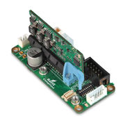
maxon motor EPOS2 Module 36/2 Hardware Reference Manual (40 pages)
36/2 Motherboard
Brand:
maxon motor
| Category:
Controller
| Size: 3 MB
Table of Contents
T Cable Ofcontents 1 about this Document 5 2 Introduction 9
3
Table of Contents
3
Table 3-9 Table
3
Table 1-1 Table
5
Documentation Structure
9
Figure 2-1 Documentation Structure
9
Components
10
Designation Order
10
EPOS2 Module 36/2 Motherboard
10
Table 2-4 EPOS2 Module 36/2 Motherboard
10
Table 2-5 Modules (Optional)
10
Table 2-6 Cables (Optional)
10
Table 4-12 Power Cable
10
Table 4-13 USB Type a - Crimp Cable
10
Table 4-14 RS232-COM Cable
10
Safety Precautions
11
EPOS2 Motherboard I/O Module
13
Document ID: Rel8458 Edition: November 2018
13
Motherboard (for 1 EPOS2 Module 36/2)
13
Figure 3-2 EPOS2 Module 36/2 Motherboard - Interfaces
13
Power Input Connector (J1)
14
Coils Output Connector (J2)
14
Figure 3-3 Power Input Connector (J1)
14
Figure 3-4 Coils Output Connector (J2)
14
Hall Sensor Input Connector (J3)
15
Encoder Input Connector (J4)
15
Figure 3-5 Hall Sensor Input Connector (J3)
15
Figure 3-6 Encoder Input Connector (J4)
15
Auxiliary I/O Connector (J5)
16
Figure 3-7 Auxiliary I/O Connector (J5)
16
Auxiliary Bay Connector (J6)
17
Figure 3-8 Auxiliary Bay Connector (J6)
17
VCC Board-To-Board Powerlink (J7A & J7B)
18
GND Board-To-Board Powerlink (J8A & J8B)
18
Figure 3-9 VCC Board-To-Board Powerlink (J7A & J7B)
18
Figure 3-10 GND Board-To-Board Powerlink (J8A & J8B)
18
CAN Bus Connector (J9 & J10)
19
CAN Link Cable
19
Figure 3-11 CAN Bus Connector (J9 & J10)
19
EPOS2 Module 36/2 Connector (J11)
20
Figure 3-12 EPOS2 Module 36/2 Connector (J11)
20
DIP Switch Bank (Sw)
22
Figure 3-13 DIP Switch Bank (Sw1)
22
Connections
13
Attachments
23
CAN Jumper (Link1)
23
Motor+ Link (Link2)
23
Motor- Link (Link3)
23
Fuse (Fuse1)
23
Fuse (Fuse2)
23
Figure 3-14 CAN Jumper (Link1)
23
Figure 3-15 Motor+ Link (Link2)
23
Figure 3-16 Motor- Link (Link3)
23
Figure 3-17 Fuse (Fuse1)
23
Status Indicators
24
Power LED (Pwr)
24
Dimensional Drawing
24
Figure 3-19 Power LED (Pwr)
24
Figure 3-20 Dimensional Drawing - Motherboard with EPOS2 Module 36/2 [MM]
24
Extension Modules
25
USB Module (407583)
25
1X USB Module
25
M3X6 MM Mounting Screw
25
Figure 4-21 USB Module - Interfaces
25
Figure 4-22 USB Connector (J1)
25
Figure 4-23 Auxiliary Port Connector (J2)
26
Figure 4-24 Transmit Data LED (Tx)
26
RS232 Module (407584)
27
1X RS232 Module
27
M3X6 MM Mounting Screw
27
Figure 4-25 Receive Data LED (Rx)
27
Figure 4-26 RS232 Module - Interfaces
27
Figure 4-27 USB Connector (J1)
27
Figure 4-28 Auxiliary Port Connector (J2)
28
Figure 4-29 Power LED (Pwr)
29
I/O Module (407585)
30
I/O Module
30
M3X6 MM Mounting Screw
30
Figure 4-30 I/O Module - Interfaces
30
Figure 4-31 I/O Connector (J1)
30
Figure 4-32 Auxiliary Port Connector (J2)
31
Figure 4-33 Power LED (Pwr)
31
Dual Encoder Module (423536)
32
1X Dual Encoder Module
32
M3X6 MM Mounting Screw
32
EPOS2 Positioning Controller EPOS2 Module 36/2 Mobo Hardware Reference
32
Figure 4-34 Dual Encoder Module - Interfaces
32
Figure 4-35 Encoder Connector (J1)
32
Figure 4-36 Auxiliary Port Connector (J2)
33
Figure 4-37 Power LED (Pwr)
33
Cables
34
Power Cable (423507)
34
USB Type a - Crimp Cable (423526)
34
RS232-COM Cable (423530)
34
L Fist Ofigures
37
Advertisement
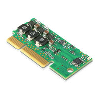
Maxon Motor EPOS2 Module 36/2 Hardware Reference Manual (52 pages)
Positioning Controller
Brand:
Maxon Motor
| Category:
Controller
| Size: 5 MB
Table of Contents
T Cable Ofcontents 1 about this Document 5 2 Introduction 9
3
Table of Contents
3
Table 3-13 Table
3
1 About this Document
5
Table 1-1 Table
5
Documentation Structure
9
Safety Precautions
10
Electrical Data
11
Table 3-5 Electrical Data - Inputs
11
Table 3-6 Electrical Data - Outputs
11
Table 31-34 Electrical Data 1-3 Rating
11
3 Technical Data
11
Mechanical Data
12
Table 3-10 Electrical Data - Leds
12
Table 3-11 Electrical Data - Connections
12
Table 3-12 Mechanical Data
12
Table 3-7 Electrical Data - Voltage Outputs
12
Table 3-8 Electrical Data - Motor Connections
12
Table 3-9 Electrical Data - Interfaces
12
Dimensional Drawings
13
Environmental Conditions
14
Order Details
14
Table 3-15 Accessories
14
Standards
15
Table 3-16 Standards
15
Pin Assignment
17
Table 4-17 EPOS2 Module 36/2 - Pin Assignment Array a
18
Minimum External Wiring
19
Table 4-18 EPOS2 Module 36/2 - Pin Assignment Array B
19
Power Supply
20
Determination of Power Supply
20
Use of Separate Logic Supply (Optional)
21
Low Supply Voltage Operation (Optional)
21
Motor Connection
22
Maxon EC Motor (Brushless)
22
Maxon DC Motor (Brushed)
22
Hall Sensor Connection
23
Encoder Connection
24
Digital Input Connection
25
Digital Inputs 1, 2, 3 and 4
25
Digital Inputs 7 and 8
27
Analog Input Connection
28
Analog Inputs 1 and 2
28
Digital Output Connection
29
Digital Outputs 1 and 2
29
Digital Output 5
31
RS232 Connection
32
CAN Connection
33
SCI Interface Connection
33
CAN Configuration
34
CAN ID (Node Address)
34
Table 4-19 CAN ID - Binary Code Values
34
Table 4-20 CAN ID - Examples
34
4.13.2 CAN Automatic Bit Rate Detection
35
Status Leds
36
Table 4-21 Leds - Interpretation of Condition
36
5 Motherboard Design Guide
37
Requirements for External Components
37
Card Edge Connector
37
Power Supply Voltage
37
Logic Supply Voltage
38
Motor Phase
39
Supplier Reference
39
Table 5-22 Recommended Components
39
Usb
40
Table 5-23 USB to UART Converter Configuration - Settings
40
Design Rules
41
Ground
41
Communication Interfaces
41
I/Os
41
Table 5-24 Functional Blocks - Ground Connections
41
Layout
42
Schematic Examples
42
Minimum External Wiring
42
Separate Logic Supply Voltage and CAN Communication
42
USB Interface
43
Wiring Example: Low Supply Voltage Operation
44
Wiring Example: Two Axes with RS232 to CAN Gateway
45
L Tist Ofables
48
Advertisement
Related Products
Maxon Motor EPOS2 24/2
Maxon Motor EPOS2 70/10
Maxon Motor EPOS2 50/5
Maxon Motor EPOS2 P 24/5
maxon motor EPOS 24/1
maxon motor EPOS 24/5
maxon motor EPOS2 24/5
Maxon Motor EPOS4 Compact 50/8 CAN
maxon motor EPOS4 Compact 24/1.5 CAN
maxon motor EPOS4 Series
Maxon Motor Categories
Controller
DC Drives
Amplifier
Control Unit
Engine
More Maxon Motor Manuals
Login
Sign In
OR
Sign in with Facebook
Sign in with Google
Upload manual
Upload from disk
Upload from URL