Table of Contents
Advertisement
Advertisement
Chapters
Table of Contents

Related Manuals for maxon motor EPOS2 70/10


Summary of Contents for maxon motor EPOS2 70/10
- Page 1 EPOS2 Positioning Controller Hardware Reference Edition December 2013 Positioning Controller Hardware Reference Document ID: rel4270 maxon motor ag Brünigstrasse 220 P.O.Box 263 CH-6072 Sachseln Phone +41 41 666 15 00 Fax +41 41 666 16 50 www.maxonmotor.com...
- Page 2 ERMISSION TO COMMENCE NSTALLATION The EPOS2 70/10 is considered as partly completed machinery according to EU’s directive 2006/42/ EC, Article 2, Clause (g) and therefore is intended to be incorporated into or assembled with other machinery or other partly completed machinery or equipment.
-
Page 3: Table Of Contents
4.13 Status LEDs..........44 maxon motor control EPOS2 Positioning Controller Document ID: rel4270 EPOS2 70/10 Hardware Reference Edition: December 2013 © 2013 maxon motor. Subject to change without prior notice. - Page 4 • • p a g e i n t e n t i o n a l l y l e f t b l a n k • • maxon motor control Document ID: rel4270 EPOS2 Positioning Controller Edition: December 2013 EPOS2 70/10 Hardware Reference © 2013 maxon motor. Subject to change without prior notice.
-
Page 5: Table 1-1 Notations Used In This Document
Use for other and/or additional purposes is not permitted. maxon motor, the manufacturer of the equip- ment described, does not assume any liability for loss or damage that may arise from any other and/or additional use than the intended purpose. - Page 6 Points out information particular to potential damage of equipment. Reference Refers to particular information provided by other parties. maxon motor control Document ID: rel4270 EPOS2 Positioning Controller Edition: December 2013 EPOS2 70/10 Hardware Reference © 2013 maxon motor. Subject to change without prior notice.
-
Page 7: Table 1-2 Brand Names And Trademark Owners
The present document – including all parts thereof – is protected by copyright. Any use (including repro- duction, translation, microfilming and other means of electronic data processing) beyond the narrow restrictions of the copyright law without the prior approval of maxon motor ag, is not permitted and sub- ject to persecution under the applicable law. - Page 8 • • p a g e i n t e n t i o n a l l y l e f t b l a n k • • maxon motor control Document ID: rel4270 EPOS2 Positioning Controller Edition: December 2013 EPOS2 70/10 Hardware Reference © 2013 maxon motor. Subject to change without prior notice.
-
Page 9: Documentation Structure
• wiring examples. maxon motor control’s EPOS2 70/10 is a small-sized, full digital, smart motion controller. Due to its flex- ible and high efficient power stage, the EPOS2 70/10 drives brushed DC motors with digital encoder as well as brushless EC motors with digital Hall sensors and encoder. -
Page 10: Safety Precautions
– and be kept – in a safe operating mode. • Be aware that you are not entitled to perform any repair on components supplied by maxon motor. Best Practice •... -
Page 11: Electrical Data
ID 1…127 configurable via DIP switch or CAN ID (CAN identification) software Table 3-4 Electrical Data – Inputs maxon motor control 3-11 EPOS2 Positioning Controller Document ID: rel4270 EPOS2 70/10 Hardware Reference Edition: December 2013 © 2013 maxon motor. Subject to change without prior notice. -
Page 12: Table 33-55 Electrical Data 3-5 Outputs
Status Indicators Operation green LED Error red LED Table 3-9 Electrical Data – LEDs maxon motor control 3-12 Document ID: rel4270 EPOS2 Positioning Controller Edition: December 2013 EPOS2 70/10 Hardware Reference © 2013 maxon motor. Subject to change without prior notice. -
Page 13: Table 3-10 Electrical Data - Connections
Molex Micro-Fit 3.0 43030-xxxx (AWG 20-30) Table 3-10 Electrical Data – Connections maxon motor control 3-13 EPOS2 Positioning Controller Document ID: rel4270 EPOS2 70/10 Hardware Reference Edition: December 2013 © 2013 maxon motor. Subject to change without prior notice. -
Page 14: Mechanical Data
Table 3-12 Environmental Conditions maxon motor control 3-14 Document ID: rel4270 EPOS2 Positioning Controller Edition: December 2013 EPOS2 70/10 Hardware Reference © 2013 maxon motor. Subject to change without prior notice. -
Page 15: Order Details
Safety Standards UL File Number E187447; unassembled printed circuit board Table 3-14 Standards maxon motor control 3-15 EPOS2 Positioning Controller Document ID: rel4270 EPOS2 70/10 Hardware Reference Edition: December 2013 © 2013 maxon motor. Subject to change without prior notice. - Page 16 • • p a g e i n t e n t i o n a l l y l e f t b l a n k • • maxon motor control 3-16 Document ID: rel4270 EPOS2 Positioning Controller Edition: December 2013 EPOS2 70/10 Hardware Reference © 2013 maxon motor. Subject to change without prior notice.
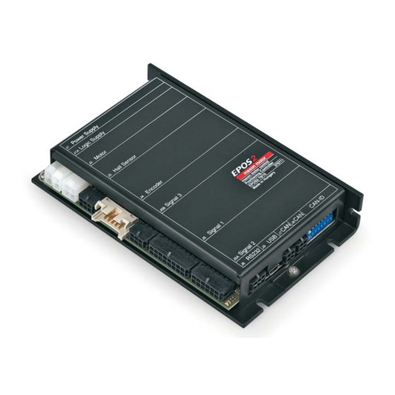
- Page 17 Connections Figure 4-3 Interfaces – Designations and Location Figure 4-4 Wiring Diagram maxon motor control 4-17 EPOS2 Positioning Controller Document ID: rel4270 EPOS2 70/10 Hardware Reference Edition: December 2013 © 2013 maxon motor. Subject to change without prior notice.
-
Page 18: Power Supply Connector (J1)
Depending on load (continuous max. 10 A / acceleration, short-time max. 25 A) 1) Calculate required voltage under load using following scheme (the formula takes a max. PWM cycle of 90% and a max. voltage drop of -1 V at EPOS2 70/10 into account): Known values: •... -
Page 19: Logic Supply Connector (J1A)
Molex Mini-Fit Jr. female crimp terminals (44476-xxxx) Suitable hand crimper Molex hand crimper (63819-0900) maxon motor control 4-19 EPOS2 Positioning Controller Document ID: rel4270 EPOS2 70/10 Hardware Reference Edition: December 2013 © 2013 maxon motor. Subject to change without prior notice. -
Page 20: Motor Connector (J2)
Motor (-M) DC motor: Motor - do not connect – Motor shield Cable shield maxon motor control 4-20 Document ID: rel4270 EPOS2 Positioning Controller Edition: December 2013 EPOS2 70/10 Hardware Reference © 2013 maxon motor. Subject to change without prior notice. -
Page 21: Hall Sensor Connector (J3)
Molex Micro-Fit 3.0 female crimp terminals (43030-xxxx) Suitable hand crimper Molex hand crimper (63819-0900) maxon motor control 4-21 EPOS2 Positioning Controller Document ID: rel4270 EPOS2 70/10 Hardware Reference Edition: December 2013 © 2013 maxon motor. Subject to change without prior notice. -
Page 22: Encoder Connector (J4)
Encoder Input Circuit for Channel A (analogously valid also for Channel B) Figure 4-11 Encoder Input Circuit for Index Channel maxon motor control 4-22 Document ID: rel4270 EPOS2 Positioning Controller Edition: December 2013 EPOS2 70/10 Hardware Reference © 2013 maxon motor. Subject to change without prior notice. - Page 23 Suitable connector DIN 41651 Plug, pitch 2.54 mm, 10 poles, plug strain relief maxon motor control 4-23 EPOS2 Positioning Controller Document ID: rel4270 EPOS2 70/10 Hardware Reference Edition: December 2013 © 2013 maxon motor. Subject to change without prior notice.
-
Page 24: Signal 1 Connector (J5)
Molex Micro-Fit 3.0 female crimp terminals (43030-xxxx) Suitable hand crimper Molex hand crimper (63819-0000) maxon motor control 4-24 Document ID: rel4270 EPOS2 Positioning Controller Edition: December 2013 EPOS2 70/10 Hardware Reference © 2013 maxon motor. Subject to change without prior notice. -
Page 25: Digital Inputs 1, 2 And 3
<300 µs @ 24 VDC Figure 4-14 DigIN1…3 Logic Level Figure 4-15 DigIN1…3 Circuit maxon motor control 4-25 EPOS2 Positioning Controller Document ID: rel4270 EPOS2 70/10 Hardware Reference Edition: December 2013 © 2013 maxon motor. Subject to change without prior notice. -
Page 26: Digital Inputs 4, 5 And 6
<300 µs @ 24 VDC Figure 4-16 DigIN4…6 Logic Level Figure 4-17 DigIN4…6 Circuit maxon motor control 4-26 Document ID: rel4270 EPOS2 Positioning Controller Edition: December 2013 EPOS2 70/10 Hardware Reference © 2013 maxon motor. Subject to change without prior notice. - Page 27 (24 V) = 3 k (200 mW) • By principle, using 2-wire proximity switches is possible. maxon motor control 4-27 EPOS2 Positioning Controller Document ID: rel4270 EPOS2 70/10 Hardware Reference Edition: December 2013 © 2013 maxon motor. Subject to change without prior notice.
-
Page 28: Supply Voltage For Digouts
Leakage current leak Switching delay <500 µs @ 24 VDC Figure 4-19 DigOUT1…3 Circuit maxon motor control 4-28 Document ID: rel4270 EPOS2 Positioning Controller Edition: December 2013 EPOS2 70/10 Hardware Reference © 2013 maxon motor. Subject to change without prior notice. -
Page 29: Digital Output 4
Wiring Example: “Permanent Magnet Brake” Figure 4-21 DigOUT4 – Wiring Example for Permanent Magnet Brake maxon motor control 4-29 EPOS2 Positioning Controller Document ID: rel4270 EPOS2 70/10 Hardware Reference Edition: December 2013 © 2013 maxon motor. Subject to change without prior notice. -
Page 30: Digital Input 11
DigIN11 Circuit Figure 4-24 DIP Switch JP4/2 – Factory Setting: “Power Stage Enable” deactivated maxon motor control 4-30 Document ID: rel4270 EPOS2 Positioning Controller Edition: December 2013 EPOS2 70/10 Hardware Reference © 2013 maxon motor. Subject to change without prior notice. -
Page 31: Signal 2 Connector (J5A)
Molex Micro-Fit 3.0 female crimp terminals (43030-xxxx) Suitable hand crimper Molex hand crimper (63819-0000) 4.7.1 Reference Output Voltage Can be used as supply voltage for external loads connected to EPOS2 70/10 analog inputs. +5VOUT Connector [J5A] Pin [1] Output voltage +5 VDC Output resistance 1.0 kΩ... -
Page 32: Analog Inputs 1 And 2
1.22 mV Bandwidth 5 kHz Figure 4-27 AnIN1 Circuit (analogously valid also for AnIN2) maxon motor control 4-32 Document ID: rel4270 EPOS2 Positioning Controller Edition: December 2013 EPOS2 70/10 Hardware Reference © 2013 maxon motor. Subject to change without prior notice. -
Page 33: Digital Inputs 7 And 8 "High Speed Command
Bandwidth 5 kHz Figure 4-29 DigIN7 “Sin/Cos” Circuit (analogously valid also for DigIN8) maxon motor control 4-33 EPOS2 Positioning Controller Document ID: rel4270 EPOS2 70/10 Hardware Reference Edition: December 2013 © 2013 maxon motor. Subject to change without prior notice. - Page 34 Max. input frequency 2.5 MHz Figure 4-30 DigIN7 “Single-ended” Circuit (analogously valid also for DigIN8) maxon motor control 4-34 Document ID: rel4270 EPOS2 Positioning Controller Edition: December 2013 EPOS2 70/10 Hardware Reference © 2013 maxon motor. Subject to change without prior notice.
-
Page 35: Signal 3 Connector (J5B)
Molex Micro-Fit 3.0 female crimp terminals (43030-xxxx) Suitable hand crimper Molex hand crimper (69819-0000) maxon motor control 4-35 EPOS2 Positioning Controller Document ID: rel4270 EPOS2 70/10 Hardware Reference Edition: December 2013 © 2013 maxon motor. Subject to change without prior notice. -
Page 36: Digital Input 9 "High Speed Command
Input low current Max. input frequency 2.5 MHz Figure 4-33 DigIN9 “Single-ended” Circuit maxon motor control 4-36 Document ID: rel4270 EPOS2 Positioning Controller Edition: December 2013 EPOS2 70/10 Hardware Reference © 2013 maxon motor. Subject to change without prior notice. -
Page 37: Auxiliary Output Voltage
4.8.2 Auxiliary Output Voltage Can be used as supply voltage for external loads connected to EPOS2 70/10 digital inputs. Connector [J5B] Pin [4] Output voltage +5 VDC (referenced to D_Gnd) Output current max. 150 mA Figure 4-34 Auxiliary Output Voltage Circuit... -
Page 38: Digital Output 5 "High Speed Output
Logic 1 >2.5 V @ 60 mA (source) Figure 4-36 DigOUT5 “Single-ended” Circuit maxon motor control 4-38 Document ID: rel4270 EPOS2 Positioning Controller Edition: December 2013 EPOS2 70/10 Hardware Reference © 2013 maxon motor. Subject to change without prior notice. -
Page 39: Rs232 Connector (J6)
Molex Micro-Fit 3.0 female crimp terminals (43030-xxxx) Suitable hand crimper Molex hand crimper (63819-0000) maxon motor control 4-39 EPOS2 Positioning Controller Document ID: rel4270 EPOS2 70/10 Hardware Reference Edition: December 2013 © 2013 maxon motor. Subject to change without prior notice. -
Page 40: Can Connector (J7, J8)
Molex Micro-Fit 3.0 female crimp terminals (43030-xxxx) Suitable hand crimper Molex hand crimper (63819-0000) maxon motor control 4-40 Document ID: rel4270 EPOS2 Positioning Controller Edition: December 2013 EPOS2 70/10 Hardware Reference © 2013 maxon motor. Subject to change without prior notice. -
Page 41: Usb Connector (J9)
Notes Suitable connector Standard USB cable with type mini B plug (5 poles) maxon motor control 4-41 EPOS2 Positioning Controller Document ID: rel4270 EPOS2 70/10 Hardware Reference Edition: December 2013 © 2013 maxon motor. Subject to change without prior notice. -
Page 42: Can Configuration (Jp1)
16 + 32 + 64 Table 4-16 CAN ID – DIP Switch Settings (Example) maxon motor control 4-42 Document ID: rel4270 EPOS2 Positioning Controller Edition: December 2013 EPOS2 70/10 Hardware Reference © 2013 maxon motor. Subject to change without prior notice. -
Page 43: Can Bus Termination
Example 1: Multiple Axis System with EPOS2 70/10 within CANopen Bus Figure 4-41 EPOS2 70/10 without CAN Bus Termination Example 2: Multiple Axis System with EPOS2 70/10 both Ends of CANopen Bus Figure 4-42 EPOS2 70/10 with CAN Bus Termination... -
Page 44: Status Leds
4.13 Status LEDs The LEDs display the current status of the EPOS2 70/10 as well as possible errors: • Green LED shows the operating status • Red LED indicates errors For detailed information separate document «EPOS2 Firmware Specification». Status / Error Green Power stage is disabled. - Page 45 EPOS2 70/10 with CAN Bus Termination........43...
- Page 46 LEDs – Interpretation of Condition ........44 maxon motor control Z-46 Document ID: rel4270 EPOS2 Positioning Controller Edition: December 2013 EPOS2 70/10 Hardware Reference © 2013 maxon motor. Subject to change without prior notice.
- Page 47 JP1, bus termination 43 of the device 9 of this document 5 maxon motor control Z-47 EPOS2 Positioning Controller Document ID: rel4270 EPOS2 70/10 Hardware Reference Edition: December 2013 © 2013 maxon motor. Subject to change without prior notice.
- Page 48 LEDs 44 supply voltage, required 18 symbols used 5 technical data 11 interface 41 maxon motor control Z-48 Document ID: rel4270 EPOS2 Positioning Controller Edition: December 2013 EPOS2 70/10 Hardware Reference © 2013 maxon motor. Subject to change without prior notice.
-
Page 49: Epos2 70/10 Hardware Reference Edition: December
• • p a g e i n t e n t i o n a l l y l e f t b l a n k • • maxon motor control Z-49 EPOS2 Positioning Controller Document ID: rel4270 EPOS2 70/10 Hardware Reference Edition: December 2013 © 2013 maxon motor. Subject to change without prior notice. - Page 50 The present document – including all parts thereof – is protected by copyright. Any use (including reproduction, translation, microfilming and other means of electronic data processing) beyond the narrow restrictions of the copyright law without the prior approval of maxon motor ag, is not permitted and subject to persecution under the applicable law. maxon motor ag Brünigstrasse 220...
Need help?
Do you have a question about the EPOS2 70/10 and is the answer not in the manual?
Questions and answers