Table of Contents
Advertisement
Quick Links
maxon motor control
EPOS2 P Programmable Positioning Controller
Hardware Reference
Edition May 2016
Programmable Positioning Controller
Hardware Reference
Document ID: rel5876
maxon motor ag Brünigstrasse 220 P.O.Box 263 CH-6072 Sachseln Phone +41 41 666 15 00 Fax +41 41 666 16 50 www.maxonmotor.com
Advertisement
Table of Contents

Related Manuals for maxon motor EPOS2 P 24/5


Summary of Contents for maxon motor EPOS2 P 24/5
- Page 1 EPOS2 P Programmable Positioning Controller Hardware Reference Edition May 2016 Programmable Positioning Controller Hardware Reference Document ID: rel5876 maxon motor ag Brünigstrasse 220 P.O.Box 263 CH-6072 Sachseln Phone +41 41 666 15 00 Fax +41 41 666 16 50 www.maxonmotor.com...
- Page 2 ERMISSION TO COMMENCE NSTALLATION The EPOS2 P 24/5 is considered as partly completed machinery according to EU directive 2006/42/EC, Article 2, Clause (g) and therefore is intended to be incorporated into or assembled with other machinery or other partly completed machinery or equipment.
-
Page 3: Table Of Contents
4.10 Status LEDs..........37 maxon motor control EPOS2 P Programmable Positioning Controller Document ID: rel5876 EPOS2 P 24/5 Hardware Reference Edition: May 2016 © 2016 maxon motor. Subject to change without prior notice. - Page 4 • • p a g e i n t e n t i o n a l l y l e f t b l a n k • • maxon motor control Document ID: rel5876 EPOS2 P Programmable Positioning Controller Edition: May 2016 EPOS2 P 24/5 Hardware Reference © 2016 maxon motor. Subject to change without prior notice.
-
Page 5: About This Document
Use for other and/or additional purposes is not permitted. maxon motor, the manufacturer of the equip- ment described, does not assume any liability for loss or damage that may arise from any other and/or additional use than the intended purpose. - Page 6 © Molex, USA-Lisle, IL Mini-Fit Jr.™ Table 1-3 Brand Names and Trademark Owners maxon motor control Document ID: rel5876 EPOS2 P Programmable Positioning Controller Edition: May 2016 EPOS2 P 24/5 Hardware Reference © 2016 maxon motor. Subject to change without prior notice.
- Page 7 The present document – including all parts thereof – is protected by copyright. Any use (including repro- duction, translation, microfilming and other means of electronic data processing) beyond the narrow restrictions of the copyright law without the prior approval of maxon motor ag, is not permitted and sub- ject to persecution under the applicable law.
- Page 8 • • p a g e i n t e n t i o n a l l y l e f t b l a n k • • maxon motor control Document ID: rel5876 EPOS2 P Programmable Positioning Controller Edition: May 2016 EPOS2 P 24/5 Hardware Reference © 2016 maxon motor. Subject to change without prior notice.
-
Page 9: Documentation Structure
EPOS2 P 24/5 is a small-sized, full digital and free programmable positioning control unit. Due to its flexible and high efficient power stage, the EPOS2 P 24/5 drives brushed DC motors with digital encoder as well as brushless EC motors with digital Hall sensors and encoder. -
Page 10: Safety Precautions
– and be kept – in a safe operating mode. • Be aware that you are not entitled to perform any repair on components supplied by maxon motor. Best Practice •... -
Page 11: Electrical Data
Digital Output 4 (“Brake”) open drain Table 3-6 Electrical Data – Outputs maxon motor control 3-11 EPOS2 P Programmable Positioning Controller Document ID: rel5876 EPOS2 P 24/5 Hardware Reference Edition: May 2016 © 2016 maxon motor. Subject to change without prior notice. -
Page 12: Table 3-7 Electrical Data - Voltage Outputs
Program error orange LED Table 3-11 Electrical Data – LEDs maxon motor control 3-12 Document ID: rel5876 EPOS2 P Programmable Positioning Controller Edition: May 2016 EPOS2 P 24/5 Hardware Reference © 2016 maxon motor. Subject to change without prior notice. - Page 13 Tyco C42334-A421-C42 (right) / Tyco C42334-A421-C52 (left) Table 3-12 Electrical Data – Connections maxon motor control 3-13 EPOS2 P Programmable Positioning Controller Document ID: rel5876 EPOS2 P 24/5 Hardware Reference Edition: May 2016 © 2016 maxon motor. Subject to change without prior notice.
-
Page 14: Mechanical Data
M3 screws Table 3-13 Mechanical Data Figure 3-2 Dimensional Drawing [mm] maxon motor control 3-14 Document ID: rel5876 EPOS2 P Programmable Positioning Controller Edition: May 2016 EPOS2 P 24/5 Hardware Reference © 2016 maxon motor. Subject to change without prior notice. -
Page 15: Environmental Conditions
EPOS2 P 24/5 Order number 378308 Table 3-15 Order Details maxon motor control 3-15 EPOS2 P Programmable Positioning Controller Document ID: rel5876 EPOS2 P 24/5 Hardware Reference Edition: May 2016 © 2016 maxon motor. Subject to change without prior notice. -
Page 16: Standards
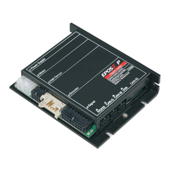
Mean Time Between Failures (MTBF): 320'814 hours Table 3-16 Standards maxon motor control 3-16 Document ID: rel5876 EPOS2 P Programmable Positioning Controller Edition: May 2016 EPOS2 P 24/5 Hardware Reference © 2016 maxon motor. Subject to change without prior notice. - Page 17 Figure 4-4 Interfaces – Designations and Location Figure 4-5 Wiring Diagram maxon motor control 4-17 EPOS2 P Programmable Positioning Controller Document ID: rel5876 EPOS2 P 24/5 Hardware Reference Edition: May 2016 © 2016 maxon motor. Subject to change without prior notice.
-
Page 18: Power Supply Connector (J1)
Depending on load (continuous max. 5 A / acceleration, short-time max. 10 A) 1) Calculate required voltage under load using following scheme (the formula takes a max. PWM cycle of 90% and a max. voltage drop of −1 V at EPOS2 P 24/5 into account): Known values: •... -
Page 19: Use Of Separate Logic Supply
Figure 4-8 Jumper JP4 – closed (left) / open (right) maxon motor control 4-19 EPOS2 P Programmable Positioning Controller Document ID: rel5876 EPOS2 P 24/5 Hardware Reference Edition: May 2016 © 2016 maxon motor. Subject to change without prior notice. -
Page 20: Motor Connector (J2)
DC motor: Motor − do not connect Motor shield Cable shield maxon motor control 4-20 Document ID: rel5876 EPOS2 P Programmable Positioning Controller Edition: May 2016 EPOS2 P 24/5 Hardware Reference © 2016 maxon motor. Subject to change without prior notice. -
Page 21: Maxon Dc Motor With Integrated Motor/Encoder Ribbon Cable
Figure 4-11 Jumpers JP2/JP3 – open (left) / closed (right) maxon motor control 4-21 EPOS2 P Programmable Positioning Controller Document ID: rel5876 EPOS2 P 24/5 Hardware Reference Edition: May 2016 © 2016 maxon motor. Subject to change without prior notice. -
Page 22: Hall Sensor Connector (J3)
Molex Micro-Fit 3.0 female crimp terminals (43030-xxxx) Notes Suitable hand crimper Molex hand crimper (63819-0000) maxon motor control 4-22 Document ID: rel5876 EPOS2 P Programmable Positioning Controller Edition: May 2016 EPOS2 P 24/5 Hardware Reference © 2016 maxon motor. Subject to change without prior notice. -
Page 23: Encoder Connector (J4)
Max. encoder input frequency 5 MHz Figure 4-14 Encoder Input Channel maxon motor control 4-23 EPOS2 P Programmable Positioning Controller Document ID: rel5876 EPOS2 P 24/5 Hardware Reference Edition: May 2016 © 2016 maxon motor. Subject to change without prior notice. - Page 24 DIN 41651 Plug, pitch 2.54 mm, 10 poles, plug strain relief Notes maxon motor control 4-24 Document ID: rel5876 EPOS2 P Programmable Positioning Controller Edition: May 2016 EPOS2 P 24/5 Hardware Reference © 2016 maxon motor. Subject to change without prior notice.
-
Page 25: Signal Connector (J5)
Molex Micro-Fit 3.0 female crimp terminals (43030-xxxx) Notes Suitable hand crimper Molex hand crimper (63819-0000) maxon motor control 4-25 EPOS2 P Programmable Positioning Controller Document ID: rel5876 EPOS2 P 24/5 Hardware Reference Edition: May 2016 © 2016 maxon motor. Subject to change without prior notice. -
Page 26: Digital Inputs 1, 2 And 3
<2 µs @ 5 VDC Figure 4-17 DigIN1 Circuit (analogously valid also for DigIN2/3) maxon motor control 4-26 Document ID: rel5876 EPOS2 P Programmable Positioning Controller Edition: May 2016 EPOS2 P 24/5 Hardware Reference © 2016 maxon motor. Subject to change without prior notice. -
Page 27: Digital Inputs 4, 5 And 6
DigIN4 Circuit (analogously valid also for DigIN5/6) For wiring examples page 4-28. maxon motor control 4-27 EPOS2 P Programmable Positioning Controller Document ID: rel5876 EPOS2 P 24/5 Hardware Reference Edition: May 2016 © 2016 maxon motor. Subject to change without prior notice. - Page 28 DigIN4 – Type NPN Proximity Switch (analogously valid also for DigIN5/6) maxon motor control 4-28 Document ID: rel5876 EPOS2 P Programmable Positioning Controller Edition: May 2016 EPOS2 P 24/5 Hardware Reference © 2016 maxon motor. Subject to change without prior notice.
-
Page 29: Analog Inputs 1 And 2
Figure 4-21 AnIN1 Circuit (analogously valid also for AnIN2) 4.5.4 Auxiliary Supply Voltage Output Can be used as supply voltage for external loads connected to EPOS2 P 24/5’s digital outputs. Connector [J5] Pin [9] D_Gnd Connector [J5] Pins [1]; [2] Output voltage +11…24 VDC... -
Page 30: Digital Outputs 1, 2 And 3
Figure 4-25 DigOUT1 “Source” Circuit (analogously valid also for DigOUT2/3) maxon motor control 4-30 Document ID: rel5876 EPOS2 P Programmable Positioning Controller Edition: May 2016 EPOS2 P 24/5 Hardware Reference © 2016 maxon motor. Subject to change without prior notice. -
Page 31: Digital Output 4
≤2 mA Max. load current load Figure 4-28 DigOUT4 “Source” Circuit maxon motor control 4-31 EPOS2 P Programmable Positioning Controller Document ID: rel5876 EPOS2 P 24/5 Hardware Reference Edition: May 2016 © 2016 maxon motor. Subject to change without prior notice. -
Page 32: Rs232 Connector (J6)
Molex Micro-Fit 3.0 female crimp terminals (43030-xxxx) Notes Suitable hand crimper Molex hand crimper (63819-0000) maxon motor control 4-32 Document ID: rel5876 EPOS2 P Programmable Positioning Controller Edition: May 2016 EPOS2 P 24/5 Hardware Reference © 2016 maxon motor. Subject to change without prior notice. -
Page 33: Can Connector (J7, J8)
Molex Micro-Fit 3.0 female crimp terminals (43030-xxxx) Notes Suitable hand crimper Molex hand crimper (63819-0000) maxon motor control 4-33 EPOS2 P Programmable Positioning Controller Document ID: rel5876 EPOS2 P 24/5 Hardware Reference Edition: May 2016 © 2016 maxon motor. Subject to change without prior notice. -
Page 34: Can Configuration (Jp1 & Jp1A)
16 + 32 + 64 Table 4-18 CAN ID – DIP Switch Settings (Example) maxon motor control 4-34 Document ID: rel5876 EPOS2 P Programmable Positioning Controller Edition: May 2016 EPOS2 P 24/5 Hardware Reference © 2016 maxon motor. Subject to change without prior notice. -
Page 35: Can Bus Termination In "Can-M" Supervisor Control (Master) Network
DIP Switch (JP1 [8]) – CAN Bus Termination in CAN-S (left “OFF” right “ON”) maxon motor control 4-35 EPOS2 P Programmable Positioning Controller Document ID: rel5876 EPOS2 P 24/5 Hardware Reference Edition: May 2016 © 2016 maxon motor. Subject to change without prior notice. -
Page 36: Usb Connector (J9)
Standard USB cable with type mini B plug (5 poles) Notes maxon motor control 4-36 Document ID: rel5876 EPOS2 P Programmable Positioning Controller Edition: May 2016 EPOS2 P 24/5 Hardware Reference © 2016 maxon motor. Subject to change without prior notice. -
Page 37: Status Leds
4.10 Status LEDs The LEDs display the current status of the EPOS2 P 24/5 as well as possible errors: • Green LED shows the operating status • Red LED indicates errors • Blue LED shows the program status • Orange LED indicates program errors ... - Page 38 • • p a g e i n t e n t i o n a l l y l e f t b l a n k • • maxon motor control 4-38 Document ID: rel5876 EPOS2 P Programmable Positioning Controller Edition: May 2016 EPOS2 P 24/5 Hardware Reference © 2016 maxon motor. Subject to change without prior notice.
- Page 39 USB Connector (J9) ...........36 maxon motor control Z-39 EPOS2 P Programmable Positioning Controller Document ID: rel5876 EPOS2 P 24/5 Hardware Reference Edition: May 2016 © 2016 maxon motor. Subject to change without prior notice.
- Page 40 LEDs – Interpretation of Condition ........37 maxon motor control Z-40 Document ID: rel5876 EPOS2 P Programmable Positioning Controller Edition: May 2016 EPOS2 P 24/5 Hardware Reference © 2016 maxon motor. Subject to change without prior notice.
- Page 41 JP1A, autobitrate detection (CAN-M) 35 JP1A, bus termination (CAN-M) 35 maxon motor control Z-41 EPOS2 P Programmable Positioning Controller Document ID: rel5876 EPOS2 P 24/5 Hardware Reference Edition: May 2016 © 2016 maxon motor. Subject to change without prior notice.
- Page 42 18 symbols used 6 technical data 11 interface 36 maxon motor control Z-42 Document ID: rel5876 EPOS2 P Programmable Positioning Controller Edition: May 2016 EPOS2 P 24/5 Hardware Reference © 2016 maxon motor. Subject to change without prior notice.
-
Page 43: Epos2 P 24/5 Hardware Reference Edition: May
• • p a g e i n t e n t i o n a l l y l e f t b l a n k • • maxon motor control Z-43 EPOS2 P Programmable Positioning Controller Document ID: rel5876 EPOS2 P 24/5 Hardware Reference Edition: May 2016 © 2016 maxon motor. Subject to change without prior notice. - Page 44 The present document – including all parts thereof – is protected by copyright. Any use (including reproduction, translation, microfilming and other means of electronic data processing) beyond the narrow restrictions of the copyright law without the prior approval of maxon motor ag, is not permitted and subject to persecution under the applicable law. maxon motor ag Brünigstrasse 220...
Need help?
Do you have a question about the EPOS2 P 24/5 and is the answer not in the manual?
Questions and answers