
Subscribe to Our Youtube Channel
Related Manuals for maxon motor EPOS 70/10


Summary of Contents for maxon motor EPOS 70/10
- Page 1 EPOS Positioning Controller Hardware Reference December 2008 Edition 70/10 Positioning Controller Documentation Hardware Reference maxon document number: 752380-04...
-
Page 2: Table Of Contents
EPOS Positioning Controller EPOS 70/10 Hardware Reference Table of contents Table of contents........................2 Table of figures ........................3 Introduction ........................... 4 How to use this guide......................4 Safety Instructions......................... 5 Performance Data ......................... 6 Electrical data........................6 Inputs .......................... -
Page 3: Table Of Figures
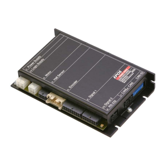
EPOS Positioning Controller EPOS 70/10 Hardware Reference Table of figures Figure 1: EPOS 70/10 photo ......................4 Figure 2: EPOS documentation hierarchy..................4 Figure 3: EPOS photo with connector description ................8 Figure 4: Wiring diagram (overview) ....................8 Figure 5: Power connector (J1)....................... -
Page 4: Introduction
EPOS Positioning Controller EPOS 70/10 Hardware Reference Introduction This documentation “Hardware Reference” provides the hardware details of the EPOS 70/10 positioning controller. It contains performance data, connections, specification, pin assignment and wiring examples. The maxon motor EPOS 70/10 is a small-sized full digital smart motion controller. -
Page 5: Safety Instructions
Danger Do ensure that during the installation of the EPOS 70/10 no apparatus is connected to the electrical supply. After switching on, do not touch any live parts! Max. -
Page 6: Performance Data
EPOS Positioning Controller EPOS 70/10 Hardware Reference Performance Data 6.1 Electrical data Power supply voltage V (Ripple < 10%) .......... 11 … 70 VDC Logic supply voltage V (Ripple < 10%) (optional) ......11 … 70 VDC Max. output voltage ..................0.9 • V Max. -
Page 7: Interfaces
EPOS Positioning Controller EPOS 70/10 Hardware Reference 6.6 Interfaces RS-232 ......RxD; TxD ......... max. 115 200 bit/s CAN (1) ......CAN_H (high); CAN_L (low) ....max.1 MBit/s CAN (2) ......CAN_H (high); CAN_L (low) ....max.1 MBit/s 6.7 LED indicator... -
Page 8: Connections 300583
EPOS Positioning Controller EPOS 70/10 Hardware Reference Connections 300583 Figure 3: EPOS photo with connector description Figure 4: Wiring diagram (overview) maxon motor control December 2008 Edition / document number 752380-04 / subject to change... -
Page 9: Power Supply Connector (J1)
Choose a power supply capable of supplying this calculated voltage under load. The formula takes a max. PWM cycle of 90 % and a 1 volts max. voltage drop at EPOS 70/10 into account. Consider: During braking of the load, the power supply must be capable of buffering the fed back energy, e.g. -
Page 10: Logic Supply Connector (J1A)
EPOS Positioning Controller EPOS 70/10 Hardware Reference 7.2 Logic supply connector (J1A) Optionally, the logic supply voltage can be sourced separately. This allows a safe and economical power backup feature. In case no separate Logic supply is applied, the Logic supply will be sourced by the Power supply voltage automatically. -
Page 11: Motor Connector (J2)
EPOS Positioning Controller EPOS 70/10 Hardware Reference 7.3 Motor connector (J2) 7.3.1 maxon EC motor Connect the maxon EC motor (brushless) motor windings on motor connector (J2). Figure 7: Motor connector (J2) Signal Description Motor winding 1 EC motor: Winding 1... -
Page 12: Hall Sensor Connector (J3)
EPOS Positioning Controller EPOS 70/10 Hardware Reference 7.4 Hall sensor connector (J3) Hall sensors are needed for detecting rotor position of maxon EC motors (brushless). Suitable for Hall Effect sensors IC using Schmitt-trigger with open collector output. Hall sensor supply voltage +5 VDC Max. -
Page 13: Encoder Connector (J4)
EPOS Positioning Controller EPOS 70/10 Hardware Reference 7.5 Encoder connector (J4) It is necessary that an encoder with a built-in line driver is used (3-channel recommended). The standard encoder adjustment (original packing) refers to a 500-count per turn encoder. For other encoders the adjustment must be modified with the software. -
Page 14: Signal 1 Connector (J5)
EPOS Positioning Controller EPOS 70/10 Hardware Reference 7.6 Signal 1 connector (J5) Signal connector contains smart multi-purpose digital I/O’s configurable as: “Positive- and Negative Limit Switches”, “Home Switch” and “Brake Output”. Additionally “General Purpose” digital I/O’s are provided. -
Page 15: Digital Input 1, 2, 3 "General Purpose
EPOS Positioning Controller EPOS 70/10 Hardware Reference 7.6.1 Digital input 1, 2, 3 “General Purpose“ These opto-isolated inputs are defined as “General Purpose” by default and can be configured via software setting. Digital input 1 [DigIN1] Connector [J5] Pin number [8]... -
Page 16: Digital Input 4, 5, 6 "Home Switch", "Positive And Negative Limit Switch
EPOS Positioning Controller EPOS 70/10 Hardware Reference 7.6.2 Digital input 4, 5, 6 "Home Switch", "Positive and Negative Limit Switch" These opto-isolated inputs are defined as: Digital input 4: “Home Switch” Digital input 5: “Positive Limit Switch“ Digital input 6: “Negative Limit Switch“... - Page 17 EPOS Positioning Controller EPOS 70/10 Hardware Reference Wiring examples: Different types of proximity switches Figure 18: Digital input 4,5, external wiring examples • Notes: Use of 3-wire PNP proximity switches is preferred. • Use of 3-wire NPN proximity switches needs an additional external pull-up resistor (12V) = 560 Ω...
-
Page 18: V Opto In" External Supply Input Voltage For Digital Outputs
EPOS Positioning Controller EPOS 70/10 Hardware Reference 7.6.3 “+V Opto IN” external supply Input voltage for Digital Outputs An external supply voltage has to be applied for supplying the EPOS 70/10 digital optical-isolated outputs. +V Opto IN [+V Opto IN]... -
Page 19: Digital Output 1, 2, 3 "General Purpose
EPOS Positioning Controller EPOS 70/10 Hardware Reference 7.6.4 Digital output 1, 2, 3 “General Purpose“ These opto-isolated outputs are defined as “General Purpose” by default and can be configured via software setting. Digital output 1 [DigOUT1] Connector [J5] Pin number [13]... -
Page 20: Digital Output 4 "Brake
EPOS Positioning Controller EPOS 70/10 Hardware Reference 7.6.5 Digital output 4 "Brake" Apply permanent magnet brake for DC voltage. Digital output 4 [DigOUT4] Connector [J5] Pin number [10] +V Opto IN [+V Opto IN] Connector [J5] Pin number [9]... -
Page 21: Signal 2 Connector (J5A)
EPOS Positioning Controller EPOS 70/10 Hardware Reference 7.7 Signal 2 connector (J5A) Signal 2 connector contains differential “High Speed Command” digital I/O’s and additionally differential analogue inputs are provided. Figure 20: Signal connector (J5A) Signal Description +5VOUT Reference Output voltage +5V... -
Page 22: Reference Output Voltage
EPOS Positioning Controller EPOS 70/10 Hardware Reference 7.7.1 Reference Output voltage Reference Output voltage can be used as supply voltage for external loads connected to EPOS 70/10 analogue inputs. Connector No. and Pin No. Connector [J5A] Pin number [1] Output voltage... -
Page 23: Analogue Input 1 "General Purpose
EPOS Positioning Controller EPOS 70/10 Hardware Reference 7.7.2 Analogue input 1 "General Purpose" “General Purpose” differential analogue input by default. Not configurable via software setting. Connector [J5A] Pin number [5] Connector No. and Pin No. Connector [J5A] Pin number [6] Input voltage range 0 ... -
Page 24: Digital Input 7 "High Speed Command
EPOS Positioning Controller EPOS 70/10 Hardware Reference 7.7.4 Digital input 7 "High Speed Command" “High Speed Command” differential input by default and can be configured via software setting. Connector [J5A] Pin number [11] Differential Connector No. and Pin No. -
Page 25: Digital Input 8 "High Speed Command
EPOS Positioning Controller EPOS 70/10 Hardware Reference 7.7.5 Digital input 8 "High Speed Command" “High Speed Command” differential input by default and can be configured via software setting. Connector [J5A] Pin number [9] Connector No. and Pin No. -
Page 26: Rs-232 Connector (J6)
EPOS Positioning Controller EPOS 70/10 Hardware Reference 7.8 RS-232 connector (J6) Maximum input voltage ± 30 V typical ± 9 V Output voltage 3kΩ to Ground Maximum bit rate 115 200 bit/s Internal RS232 driver/receiver EIA RS232 standard Note: •... -
Page 27: Can Connector (J7, J8)
EPOS Positioning Controller EPOS 70/10 Hardware Reference 7.9 CAN connector (J7, J8) Standard type CAN high-speed ISO 11898 compatible Maximum bit rate 1 MBit/s Max. number of CAN nodes Protocol CANopen DS-301 V4.02 Identifier setting by DIP-Switch or software... -
Page 28: Can Node Identification (Jp 1)
EPOS Positioning Controller EPOS 70/10 Hardware Reference 7.10 CAN Node Identification (JP 1) The CAN-ID (node address) is set at DIP-Switch 1 ... 7. All addresses can be coded from 1 ... 127 using the binary code. Binary... -
Page 29: Led Status
EPOS 70/10 Hardware Reference LED status The green LED shows the operating status and the red LED indicates an error of the positioning controller EPOS 70/10. Detailed information may be found in the Firmware Specification document. Red LED Green LED...
Need help?
Do you have a question about the EPOS 70/10 and is the answer not in the manual?
Questions and answers