
Related Manuals for maxon motor EPOS 24/1


Summary of Contents for maxon motor EPOS 24/1
- Page 1 EPOS Positioning Controller Hardware Reference December 2008 Edition 24/1 Positioning Controller Documentation Hardware Reference maxon document number: 573047-09...
-
Page 2: Table Of Contents
EPOS Positioning Controller EPOS 24/1 Hardware Reference Table of contents Table of contents........................2 Table of figures ........................3 Introduction ........................... 4 How to use this guide......................4 Safety Instructions......................... 5 Performance Data ......................... 6 Electrical data........................6 Inputs .......................... -
Page 3: Table Of Figures
Figure 5: EPOS 24/1 for maxon EC 6 motor connector description ..........9 Figure 6: Wiring diagram for maxon EC 6 motor (overview)............9 Figure 7: EPOS 24/1 for maxon EC 16/EC 22 motors connector description ......10 Figure 8: Wiring diagram for maxon EC 16/EC 22 motors (overview).......... 10 Figure 9: Connector (J1) ....................... -
Page 4: Introduction
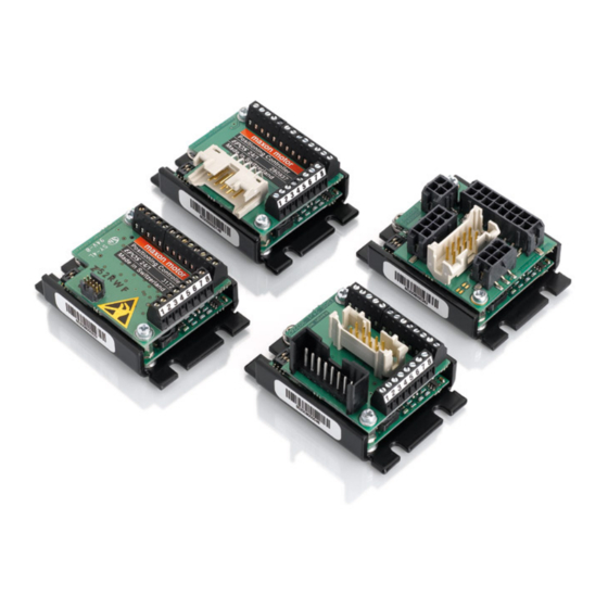
EPOS Positioning Controller EPOS 24/1 Hardware Reference Introduction This documentation “Hardware Reference” provides the hardware details of the EPOS 24/1 positioning controller. It contains performance data, connections, specification, pin assignment and wiring examples. The maxon motor EPOS 24/1 is a small-sized full digital smart motion controller. -
Page 5: Safety Instructions
Danger Do ensure that during the installation of the EPOS 24/1 no apparatus is connected to the electrical supply. After switching on, do not touch any live parts! Max. -
Page 6: Performance Data
Max. speed (motors with 2 poles ............25 000 rpm EPOS 24/1 for DC/EC motors: ..150 µH / 1 A Built-in motor choke per phase: EPOS 24/1 for EC 6 motor: ..300 µH / 0.7 A 6.2 Inputs Hall sensor signals ...... -
Page 7: Ambient Temperature- / Humidity Range
Motor / Hall ............SMD Flex Print Connector; 8 poles ..................pitch 0.5mm, top contact style EPOS 24/1 for maxon EC 16/EC 22 motors #302267 ..............with digital Hall sensors and MR-Encoder Motor / Hall ........... STOCKO MKS1658; 8 poles; pitch 2.5 mm Encoder ................ -
Page 8: Connections 280937, 317270, 302267
EPOS 24/1 Hardware Reference Connections 280937, 317270, 302267 EPOS 24/1 for maxon DC motors #280937 Figure 3: EPOS 24/1 for maxon DC motors connector description Figure 4: Wiring diagram for maxon DC motors (overview) maxon motor control December 2008 Edition / document number 573047-09 / subject to change... -
Page 9: Figure 5: Epos 24/1 For Maxon Ec 6 Motor Connector Description
EPOS Positioning Controller EPOS 24/1 Hardware Reference EPOS 24/1 for maxon EC 6 motor #317270 Figure 5: EPOS 24/1 for maxon EC 6 motor connector description Figure 6: Wiring diagram for maxon EC 6 motor (overview) maxon motor control December 2008 Edition / document number 573047-09 / subject to change... -
Page 10: Figure 8: Wiring Diagram For Maxon Ec 16/Ec 22 Motors (Overview)
EPOS Positioning Controller EPOS 24/1 Hardware Reference EPOS 24/1 for maxon EC 16/EC 22 motors #302267 Figure 7: EPOS 24/1 for maxon EC 16/EC 22 motors connecto description Figure 8: Wiring diagram for maxon EC 16/EC 22 motors (overview) maxon motor control... -
Page 11: Connector (J1)
EPOS Positioning Controller EPOS 24/1 Hardware Reference 7.1 Connector (J1) Signal connector contains multi-purpose digital I/O’s. The digital inputs are configurable as: “Home Switch” or “Positive- or Negative Limit Switch”. Additionally “General Purpose” digital I/O’s are provided. Figure 9: Connector (J1) -
Page 12: Digital Input 1 "General Purpose
EPOS Positioning Controller EPOS 24/1 Hardware Reference 7.1.1 Digital input 1 “General Purpose“ “General Purpose” input by default and can be configured via software setting. Connector No. and Pin No. Connector [J1] Pin number [1] Input voltage 0 ... 24 VDC Max. -
Page 13: Digital Input 3 "General Purpose
EPOS Positioning Controller EPOS 24/1 Hardware Reference 7.1.3 Digital input 3 "General Purpose" “General Purpose” input by default and can be configured via software setting. Connector No. and Pin No. Connector [J1] Pin number [3] Input voltage 0 ... 24 VDC Max. -
Page 14: Digital Input 4 "Home Switch
EPOS Positioning Controller EPOS 24/1 Hardware Reference 7.1.4 Digital input 4 "Home Switch" Determine the absolute position of the axis. “Home Switch” input by default and can be configured via software setting. Connector No. and Pin No. Connector [J1] Pin number [4] Input voltage 0 ... -
Page 15: Digital Input 5 "Positive Limit Switch
EPOS Positioning Controller EPOS 24/1 Hardware Reference 7.1.5 Digital input 5 "Positive Limit Switch" “Positive Limit Switch” input by default and can be configured via software setting. Connector No. and Pin No. Connector [J1] Pin number [5] Input voltage 0 ... -
Page 16: Digital Input 6 "Negative Limit Switch
EPOS Positioning Controller EPOS 24/1 Hardware Reference 7.1.6 Digital input 6 "Negative Limit Switch" “Negative Limit Switch” input by default and can be configured via software setting. Connector No. and Pin No. Connector [J1] Pin number [6] Input voltage 0 ... -
Page 17: Auxiliary Output Voltage
EPOS 24/1 Hardware Reference 7.1.7 Auxiliary output voltage Auxiliary output voltage can be used as power supply for external devices (switches…) connected to EPOS 24/1 digital inputs. The auxiliary output voltage is short circuit protected. Connector No. and Pin No. -
Page 18: Digital Output 3 "General Purpose
EPOS Positioning Controller EPOS 24/1 Hardware Reference 7.1.8 Digital output 3 "General Purpose" “General Purpose” output by default and can be configured via software setting. Connector No. and Pin No. Connector [J1] Pin number [9] Open Collector (internal pull-up... -
Page 19: Digital Output 4 "General Purpose
EPOS Positioning Controller EPOS 24/1 Hardware Reference 7.1.9 Digital output 4 "General Purpose" “General Purpose” output by default and can be configured via software setting. Connector No. and Pin No. Connector [J1] Pin number [10] Open Collector (internal pull-up... -
Page 20: Supply Voltage
Choose a power supply capable of supplying this calculated voltage under load. The formula takes a max. PWM cycle of 98 % and a 1 Volt maximum voltage drop at EPOS 24/1 into account. Consider: During braking of the load, the power supply must be capable of buffering the fed back energy, e.g. -
Page 21: Connector (J2)
EPOS Positioning Controller EPOS 24/1 Hardware Reference 7.2 Connector (J2) Connector J2 contains CAN bus and RS232 communication signals. Additional multi-purpose analogue inputs are provided. Figure 28: Connector (J2) Signal Description CAN high CAN high bus line CAN low... -
Page 22: Can Communication
EPOS Positioning Controller EPOS 24/1 Hardware Reference 7.2.1 CAN communication CAN high Connector [J2] Pin number [1] CAN low Connector [J2] Pin number [2] Connector [J2] Pin number [5] Standard type CAN high-speed ISO 11898 compatible Maximum bit rate 1 MBit/s Max. -
Page 23: Analogue Input 1 "General Purpose
EPOS Positioning Controller EPOS 24/1 Hardware Reference 7.2.3 Analogue input 1 "General Purpose" “General Purpose” analogue input by default. Not configurable via software setting. Connector No. and Pin No. Connector [J2] Pin number [6] Input voltage range 0 ... 5 VDC Max. -
Page 24: Motor / Encoder / Hall Sensor Connectors
EPOS Positioning Controller EPOS 24/1 Hardware Reference 7.3 Motor / Encoder / Hall sensor connectors 7.3.1 maxon DC motor with integrated motor / encoder ribbon cable (J3) Connect the maxon DC motor on Motor / Encoder connector (J3). -
Page 25: Maxon Ec 6 Motor With Hall Sensor And Digital Mr-Encoder
Encoder Channel A Channel B Encoder Channel B 7.3.2.1 maxon motor control Adapter 317228 (included in delivery of article 317270) Connect the maxon motor control cable order number 281074 to Motor / Hall sensor / Encoder connector (J5). Adapter 317228... -
Page 26: Figure 37: Encoder Input Circuit
EPOS Positioning Controller EPOS 24/1 Hardware Reference Connect the maxon MR-Encoder cable to connector (J6). MR-Encoder (J6) Figure 36: MR-Encode connector (J6) Signal Description + 5 VDC / 100 mA Encoder supply voltage +5 VDC / 100 mA... -
Page 27: Figure 38: Motor / Hall Sensor Connector (J7)
EPOS Positioning Controller EPOS 24/1 Hardware Reference Connect the maxon Motor / Hall sensor cable to connector (J7). Motor / Hall sensor (J7) Figure 38: Motor / Hall sensor connector (J7) Signal Description Motor winding 3 EC 6 motor winding 3... -
Page 28: Maxon Ec 16/Ec 22 Motor With Hall Sensor And Digital Mr-Encoder
EPOS Positioning Controller EPOS 24/1 Hardware Reference 7.3.3 maxon EC 16/EC 22 motor with Hall sensor and digital MR-Encoder Connect the maxon EC 16/EC 22 motor on Motor / Hall sensor connector (J8). Motor / Hall sensor connector (J8) -
Page 29: Figure 41: Encoder Connector (J9)
EPOS Positioning Controller EPOS 24/1 Hardware Reference 7.3.3.1 Encoder connector (J9) Connect the Encoder on Encoder connector (J9). Encoder connector (J9) Figure 41: Encoder connector (J9) Signal Description n.c. Not connected +5 VDC / 100 mA Encoder supply voltage Ground n.c. -
Page 30: Connections 302287
EPOS 24/1 Hardware Reference Connections 302287 EPOS 24/1 for maxon DC/EC motors #302287 Figure 43: EPOS 24/1 for maxon DC/EC motors connector description Figure 44: Wiring diagram for maxon DC/EC motors (overview) maxon motor control December 2008 Edition / document number 573047-09 / subject to change... -
Page 31: Motor / Hall Sensor Connector (J10)
+5VDC / 30 mA Hall sensor 1 Hall sensor 1 input Ground of Hall sensor supply Motor winding 2 Winding 2 Accessories: EPOS 24/1 Motor / Hall sensor cable maxon order number: 302948 Notes: Suitable connector: Molex Micro-Fit 3.0 8 poles... -
Page 32: Motor / Encoder Connector (J11)
EPOS Positioning Controller EPOS 24/1 Hardware Reference 8.2 Motor / Encoder connector (J11) Connect the Encoder cable or the Encoder cable with integrated motor lines on Encoder connector (J11). Figure 46: Encoder connector (J11) 8.2.1 maxon EC motor or maxon DC motor with separated motor and encoder cable This is the standard adjustment (factory setting). -
Page 33: Maxon Dc Motor With Integrated Motor / Encoder Ribbon Cable
EPOS Positioning Controller EPOS 24/1 Hardware Reference 8.2.2 maxon DC motor with integrated motor / encoder ribbon cable To use the EPOS 24/1 #302287 with small DC motors with integrated motor / encoder ribbon cable, two simple modifications have to be done: •... -
Page 34: Rs232 Connector (J12)
EPOS Positioning Controller EPOS 24/1 Hardware Reference 8.3 RS232 connector (J12) Figure 49: RS232 connector (J12) Signal Description RS232 RxD EPOS RS232 receive RS232 TxD EPOS RS232 transmit n.c. Not connected RS232_Ground RS232_Ground Shield Cable shield Accessories: EPOS RS232-COM cable... -
Page 35: Can Connector (J13)
EPOS Positioning Controller EPOS 24/1 Hardware Reference 8.4 CAN connector (J13) Figure 50: CAN connector (J13) Signal Description CAN high CAN high bus line CAN low CAN low bus line CAN GND CAN Ground CAN shield Cable shield... -
Page 36: Power / Signal Connector (J14)
EPOS Positioning Controller EPOS 24/1 Hardware Reference 8.5 Power / Signal connector (J14) Power / Signal connector contains smart multi-purpose digital I/O configurable as: “Positive- and Negative Limit Switches” and “Home Switch”. Additionally “General Purpose” digital I/O's and analogue inputs are provided. -
Page 37: Can Node Identification (Jp 1)
EPOS Positioning Controller EPOS 24/1 Hardware Reference CAN Node Identification (JP 1) The CAN-ID (node address) is set at DIP-Switch 1 ... 4. All addresses can be coded from 1 ... 15 using the binary code. Binary Switch... -
Page 38: Led Status
EPOS 24/1 Hardware Reference 10 LED status The green LED shows the operating status and the red LED indicates an error of the positioning controller EPOS 24/1. Detailed information may be found in the Firmware Specification document. Red LED Green LED... -
Page 39: Figure 54: Dimensions Epos 24/1 For Ec 6 Motor 317270
EPOS Positioning Controller EPOS 24/1 Hardware Reference Figure 54: Dimensions EPOS 24/1 for EC 6 motor 317270 Figure 55: Dimensions EPOS 24/1 for EC 16/EC 22 motors 302267 Figure 56: Dimensions EPOS 24/1 for DC/EC motors 302287 maxon motor control...
Need help?
Do you have a question about the EPOS 24/1 and is the answer not in the manual?
Questions and answers