
Subscribe to Our Youtube Channel
Related Manuals for Bolin Technology FEX Series


Summary of Contents for Bolin Technology FEX Series
- Page 1 FEX SERIES FIXED FHD SDI + IP ZOOM CAMERA USER MANUAL PART ONE VERSION: FEX-SN-M12082018 © 2018 Bolin Technology...
-
Page 2: Table Of Contents
Contents CAMERA USER MANUAL .................................. 4 IMPORTANT INFORMATION ................................4 OVERVIEW ....................................... 7 (B-C ) .................................... 7 EATURES LASS WHAT’S IN THE BOX ..................................... 8 ) ..................................8 CCESSORIES PTIONAL CAMERA DIAGRAMS ..................................9 INSTALLING YOUR CAMERA ................................10 RJ45 W ........................... - Page 3 ................................错误!未定义书签。 ETWORK ................................... 错误!未定义书签。 YSTEM ..................................错误!未定义书签。 VENT ................................. 错误!未定义书签。 TORAGE...
-
Page 4: Camera User Manual
Before operating the unit, please read this manual thoroughly and retain it for future reference. Copyright Copyright 2015-2018 Bolin Technology all rights reserved. No part of this manual may be copied, reproduced, translated, or distributed in any form or by any means without prior consent in writing from our company. - Page 5 We will readily improve or update the products or procedures described in the manual. Best effort has been made to verify the integrity and correctness of the contents in this document, but no statement, information, or recommendation in this manual shall constitute formal guarantee of any kind, expressed or implied. We shall not be held responsible for any technical or typographical errors in this manual.
- Page 6 Safety Information WARNING! Installation and removal of the unit and its accessories must be carried out by qualified personnel. You must read all of the Safety Instructions supplied with your equipment before installation and operation. Warnings: If the product does not work properly, please contact your dealer. Never attempt to disassemble the camera yourself. (We will not assume any responsibility for problems caused by unauthorized repair or maintenance.) ...
-
Page 7: Overview
Overview This user guide is suitable for the following models: If the model numbers that have following letter included in the end, means some extra features included: B Class – Use for broadcasting, SDI video format 1080P and 1080I supported, frame rate up to 60/59.94. It supports not only PELCO D/P, IP ONVIF but also VISCA and VISCA OVER IP control. -
Page 8: What's In The Box
WHAT’S IN THE BOX Accessories (Optional) -
Page 9: Camera Diagrams
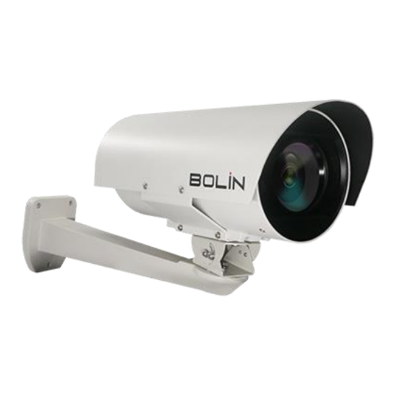
Camera Diagrams Camera 1. Infrared LED Lights 2. Camera Lens, 30X zoom 3. Infrared LED Lights 4. Sunshield 5. Nitrogen Pressurization Schrader Valve (For Factory Use Only) 6. Handle 7. MS Connector (Male), SDI+IP+12VDC+POE+RS422 connection. 8. Nitrogen Pressurization Schrader Valve (For Factory Use Only) 9. -
Page 10: Installing Your Camera
Installing Your Camera NOTE: The camera is completely sealed with pressurized nitrogen inside. Do not open your camera nor release the Nitrogen air from the Schrader Valves without authorization from a BOLIN Technology Support representative Opening the camera and / or releasing the nitrogen from inside the it may damage the camera. This will void the warranty. -
Page 11: Make The Rj45 Connector
NOTE: Please install the connector properly as the following picture: NOTE: The connector that has been installed properly should be like the picture below: Make the RJ45 connector... -
Page 12: Make The Rs422 Control Connector
Make the RS422 control connector Make the BNC SDI video connector... -
Page 13: Make The 12Vdc Power Connector
Make the 12VDC power connector The power connector type is 5.5x2.1mm Jack. Cable Requirements Network Cable: 10/100 Mbps Ethernet CAT 5/5E/6 UTP cables are applicable to the ANSI/EIA/TIA-568A/B and ISO/D. Eight wires in the network cable need to be inserted in parallel into the top of the cable connector. -
Page 14: Install The Tail Cable
Stranding Material Nominal Diameter Solid Bare Copper 0.04 in. Shield Material Type Layer Material Coverage Tape Aluminum / Polyester / Aluminum 100% Braid Tinned Copper Nom. Capacitance Conductor to shield Nom. Inductance Nom. Char. Impedance 16.2 pF/ft 0.106 µ H/ft 75 Ohm Install the Tail Cable Install and detach the Tail Cable included with the product as following:... -
Page 15: Power Connection
2. Verify that the mounted position meets the bearing requirements. Otherwise, you are advised to reinforce the mounted position to support the device weight. For more information, see the product datasheet. 3. Verify lightning protection and grounding requirements 4. Ground the terminal properly. NOTE: ... - Page 16 If you want the camera address to be automatically assigned by the VISCA controller, keep the camera address as the default address (set the camera address to 0 using the DIP switches). Reboot the camera by turning it Off/On after the camera address has been set up correctly. Camera RS422 control supports Daisy Chain connection up to 7 cameras.
- Page 17 RS422 VISCA connection with Bolin KBD-1010 controller How to make 1 to 1 RS422 connection with Bolin KBD-1010 controller as below or refer to Bolin KBD-1010 user guide. 1 to 1 RS422 connection, use Junction Box connection.
- Page 18 How to make RS422 Daisy Chain multiple camera connection with Bolin KBD-1010 controller as below or refer to Bolin KBD- 1010 user guide RS422 Daisy Chain connection, use Junction Box connection...
-
Page 19: Pelco P/D Keyboard Rs485 Connection
Daisy Chain PELCO P/D Keyboard RS485 Connection Follow the connection below to make the RS485 control connection for the keyboard controller. The camera default address is set to 1, default Baud Rate is set to 9600. Set the keyboard controller Baud Rate to 9600. The Baud Rate of the camera and the controller must be the same. Use the keyboard controller to change the camera address. - Page 20 1 to 1 RS485 connection. For how to make the connection on the controller, please refer to the controller user guide. RS485 Daisy Chain multiple camera connection. To make the connection on the controller, please refer to controller user guide. RS485 PELCO connection with Bolin KBD-1010 controller How to make 1 to 1 RS485 connection with Bolin KBD-1010 controller as below or refer to Bolin KBD-1010 user guide.
- Page 21 How to make RS485 Daisy Chain multiple camera connection with Bolin KBD-1010 controller as below or refer to Bolin KBD- 1010 user guide RS485 Daisy Chain connection, use Junction Box connection...
- Page 22 Daisy Chain Note For VISCA / PELCO control, this unit supports daisy chain connection for using multiple cameras.
-
Page 23: Visca Over Ip Control
For control details, refer to Operating Instructions of control keyboard/station software. You need to match the communication speed (Baud Rate) between the camera and the joystick controller. Operating Multiple Cameras Using RS422/485 Using RS-422 (VISCA), you can connect to 7 cameras. ... - Page 24 Physically connect the network port on the camera to the network switch Set the IP address and other network information appropriately to communicate on your network Connect the VISCA over IP-compatible controller to the network Configure the controller to access the camera’s IP address and VISCA over IP port ...
-
Page 25: Setup Camera Id, Baud Rate And Control Protocol
Setup Camera ID, Baud Rate and Control Protocol 1. For you to control a camera, the camera ID, baud rate and control protocol must be set up in advance. The baud rate and the camera ID setting within the Camera must match the baud rate and camera ID setting on the system/control keyboard. -
Page 26: Controlling The Camera
Controlling the Camera Adjusting and Setting with Menus About On-Screen Menus You can change various settings, such as shooting conditions and system setup of the camera, while observing menus displayed on a connected computer screen. This section explains how to read the on-screen menus before starting menu operations. The menu parameters may vary according to the different product model numbers. -
Page 27: The On-Screen Menu Configuration
The On-Screen Menu Configuration CALL 95 PRESET EXPOSURE AE MODE FULL AUTO IRIS PRIOR CLOSE, F14, F11, F9.6, F8, F6.8,F5.6,F4.8, F4,F3.4,F2.8,F2.4,F2.0,F1.6 SHUTTER 1/1,1/2,1/4,1/8,1/15,1/30,1/60, 1/90, 1/100, 1/125, 1/180, 1/250, 1/350, 1/500, 1/725, 1/1000, 1/1500, 1/2000, 1/3000, 1/4000, 1/6000, 1/10K sec BRIGHT 0-31 MANUAL GAIN... - Page 28 SYSTEM SETUP FACTORY DEFAULT DISPLAY CONFIGURATION ZOOM LENS OFF, ON DIRECTION OFF, ON EXIT INTERFACE SET CAMERA ID 1…255 BAUD RATE 2400, 4800, 9600 ,38400 FACTORY FORMAT EXIT FLIP OFF, ON SDI VIDEO 1080p60, 1080i60, 1080p30, 720p60, 720p30 , 1080p29.97, 1080i59.94, 1080p59.94, 1080p50, 1080i50, 1080p25, 720p50, 720p25, 720p59.94 SYSTEM INFO...
-
Page 29: Exposure Menu
EXPOSURE Menu >EXPOSURE The EXPOSURE menu is used to set the items related to exposure. >WHITE BALANCE AE MODE (Exposure Mode) >PICTURE >LENS PARAMETERS FULL AUTO: The exposure is adjusted automatically using the sensitivity of the >SYSTEM SETUP >FUNCTION SETTING image sensor, electronic shutter speed, and iris. -
Page 30: White Balance Menu
WHITE BALANCE Menu The WHITE BALANCE menu is used to select the white balance mode. >EXPOSURE >WHITE BALANCE MODE (white balance mode) >PICTURE Select the white balance mode from the following: >LENS PARAMETERS >SYSTEM SETUP >FUNCTION SETTING AUTO: This mode computes the white balance value output using color >SAVE AND EXIT information from the entire screen. -
Page 31: Picture Menu
NOTE: When you select USER, R. GAIN (red gain) and B. GAIN (blue gain) appear. You can select each item in the range from 0 to 255. OUTDOOR AUTO: This is an auto white balance mode specifically for outdoors. It allows you to capture images with natural white balance in the morning and evening. - Page 32 NONE: No effect. A/F: After operating the camera, the mode of focus be changed to auto form DIGITAL ZOOM: OFF JOYSTICK RECOVER:NONE manual. A/F RECOVER TIME: 000 A/I: After operating the camera, the mode of IRIS be changed to auto form A/I RECOVER TIME: 000 manual.
-
Page 33: System Setup Menu
SYSTEM SETUP Menu >EXPOSURE The SYSTEM SETUP menu is used to set the items related to the camera system >WHITE BALANCE >PICTURE FACTORY DEFAULT: >LENS PARAMETERS The menu is used to restore the factory settings >SYSTEM SETUP >FUNCTION SETTING >SAVE AND EXIT DISPLAY CONFIGURATION: >EXIT Entered the menu of DISPLAY CONFIGURATION, it will be shown the below items:... -
Page 34: Video Format: Sdi + Ip True Dual Output
VIDEO FORMAT: SDI + IP True Dual Output: The SDI video output and the IP video output can be configured independently. Each can be set to its own resolution. The IP and SDI can output separate video resolutions simultaneously. SDI output options: B-Class models: ... - Page 35 SYSTEM INFO: CAMERA ID :01 CAMERA ID: Modify in the menu of “INTERFACE SET” BAUD RATE :9600 BAUD RATE: Modify in the menu of “INTERFACE SET” SDI VIDEO:1080P/30 IP VIDEO :1080P SDI VIDEO: Modify in the menu of “INTERFACE SET” SV: S0A0700S010801A15 IP VIDEO: Modify in the menu of “INTERFACE SET”...
- Page 36 In order to use the special functions of the camera, the following presets are predefined for specific functions (You can find the default predefined preset at Web interface, Setup -> PTZ -> Advanced Settings): Preset number Set / call Function description Lens Reset Call Activate Backlight...
- Page 37 Preset Number DEFAULT Preset Number DEFAULT Preset Number DEFAULT DWELL DWELL DWELL ② ① ③ ④ ⑤ ⑥ RUN CONTINOUSELY: start the tour that has been set. EXIT: Push the joystick to the right to exit this level menu. PATTERN SETUP: A pattern is a memorized, repeating series of pan, tilt, zoom, and preset functions that can be recalled with a command from a controller or automatically by a programmed function (alarm, park, event, or power-up).
- Page 38 2082 TECHNOLOGY LLC BOLIN TECHNOLOGY...
Need help?
Do you have a question about the FEX Series and is the answer not in the manual?
Questions and answers