
Related Manuals for Bolin Technology VCC-8-4K20S-3SMB


Summary of Contents for Bolin Technology VCC-8-4K20S-3SMB
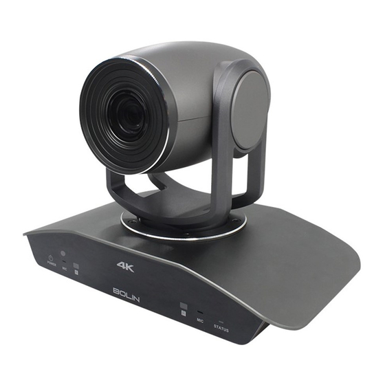
- Page 1 4K HDBaseT PTZ Camera USER MANUAL VERSION: VCC-4KHDB-M-11252018 VCC-8-4K20S-3SMB © 2018 Bolin Technology...
-
Page 2: Table Of Contents
Contents IMPORTANT INFORMATION ..............................3 WHAT’S IN THE BOX ................................. 5 OVERVIEW ....................................6 ..................................... 6 ODEL UMBERS FEATURES ....................................6 CAMERA DIAGRAMS ................................. 7 ......................................7 AMERA ................................... 8 ECEIVER ..................................9 EMOTE ONTROLLER SYSTEM CONFIGURATION ............................... 10 ....................................10 ONNECTION .................................. -
Page 3: Important Information
Before operating the unit, please read this manual thoroughly and retain it for future reference. Copyright Copyright 2015-2018 Bolin Technology all rights reserved. No part of this manual may be copied, reproduced, translated, or distributed in any form or by any means without prior consent in writing from our company. - Page 4 provided in this manual. Use of this document and the subsequent results shall be entirely on the user’s own responsibility. Safety Information WARNING! Installation and removal of the unit and its accessories must be carried out by qualified personnel. You must read all of the Safety Instructions supplied with your equipment before installation and operation.
-
Page 5: What's In The Box
WHAT’S IN THE BOX Camera: HDBaseT Receiver (Not included with the camera, order separately) Accessories (Optional) -
Page 6: Overview
Overview Model Numbers This user guide is suitable for the following models: VCC-8-4K20S-3SMB VCC-8-4K-BR (For use with HDBaseT Model, not included with the camera, order separately) Features Resolution: 4K,1080P,720P Zoom: Optical 20X, Digital 12X. SRZ Feature: Up to 30X in 4K and 40X in FHD via Super Resolution Zoom ... -
Page 7: Camera Diagrams
Camera Diagrams Camera 1. 12V DC Power Port Connect the supplied DC power adaptor and cord. 2. CVBS Video output 3. 3.5mm Audio Input 4. RS-422/485 Control Port RJ45 to RS422 extension cable is provided. (For more detail of extension cable see page15) 5. -
Page 8: Hdbaset Receiver
Do not use it as an IP video encoder. It is not for use with model VCC-8-4K20S-3SMB. 19. IR Remote Controller Indicator These are sensors to receive commands from infrared remote controller, distance up to 10 meters. -
Page 9: Remote Controller
Remote Controller 1. Power Power ON the camera to turn the camera in operation status. Power OFF the camera to turn the camera in standby status. When the camera is powered OFF, the camera turns to the back and would be on standby mode. ... -
Page 10: System Configuration
System Configuration Connection When the camera is connected to a computer and joystick keyboard with a VISCA cable (cross type, RS-232), you can operate the camera with the computer and the joystick keyboard. When the camera is connected to a joystick keyboard a control cable (cross type, RS-422/485), you can operate the camera’s pan, tilt, zoom with the joystick keyboard. -
Page 11: Obtain Video Signal
In this connection configuration, HDMI cable, SDI video cable, data cable, Network cable is required. To obtain these third party components or accessories, consult the dealer where you bought your camera. Power Use only the DC power adaptor (JEITA type4) supplied with the unit. Do not use any other DC power adaptor. -
Page 12: Camera Control Methods And System Configurations
Camera Control Methods and System Configurations This unit has multiple ways of controlling the camera and various system configuration capabilities using optional products. This section describes ways of controlling and typical system examples with the required components and usage of each system. 1. - Page 13 An application software that supports this unit is needed if you use PC station. RS232 Connection 1. Set RS232 control method on Bottom Dip Switch. 2. Set Baud Rate on Bottom Dip Switch to the same as Baud Rate setting on the keyboard you are using. Set specific camera address that you want to control the camera for on Bottom Dip Switch.
- Page 14 Use RS-422(VISCA)/RS-485 (PELCO P/D) You can use RS-422/485 port connect to optional controllers, such as joystick control keyboard, control PC station, to operate the camera. To perform pan/tilt and zoom operations using the joystick of the control keyboard, and to perform the Preset operation using the control buttons.
- Page 15 SONY Keyboard RS422 Connection VISCA (Non-Sony) Keyboard RS422 Connection PELCO P/D Keyboard RS485 Connection Use PELCO P/D compatible keyboard. Use preset 95# on the keyboard to bring up/exit camera OSD menu. Use joystick and Button “OPEN” or “CLOSE” to navigate OSD menu. To operate keyboard, please refer to the user manual of the keyboard you are using.
-
Page 16: Control The Camera Using Hdbaset Receiver
Control the camera using HDBaseT Receiver Must set the camera in RS232 control method on Bottom Dip Switch. Set Baud Rate on Bottom Dip Switch to the same as Baud Rate setting on the keyboard you are using. Reboot the camera by turning it Off/On after the Bottom Dip Switch has been set up correctly. Device supports RS232 and RS422/485 control. - Page 17 RS422: Make RJ45 connector for HDBaseT Receiver RS422 port as following: The RS232/RS422 serial port connection on controller side, please refer to the userguide of the controller. Use extension cables included to connect the RS232/RS422 control cable to the controller: RJ45 to RS232 extension adapter cable.
- Page 18 RJ45 to RS422 extension adapter cable. Make the RS422 connection as following pinout definition instruction: If you have more than one HDBaseT receivers to make multiple camera connection for RS422 daisy chain control, please refer to Page 14 (How to connect multiple cameras). ...
-
Page 19: Bottom Dip Switch Settings
BOTTOM DIP SWITCH SETTINGS The bottom dip switch is for setting the camera configuration for following items: 1. Camera ID Address for RS-485 PELCO protocol 2. Video output / Video color space 3. RS-232 / RS-422/485 selection 4. RS-232 / RS-422/485 baud rate 5. - Page 20 Bit 1~4: Video resolution setting Bit 5~6: Reserve Bit 7~8: IR remote controller ID setting SW2 Factory default setting is: OFF OFF.ON.ON.OFF.OFF.OFF.OFF. 1. Video Resolution Setting Video Resolution 1080i59.94 1080P50 720P59.94 1080P59.94 HDMI: 2160P29.97 SDI: 1080P59.94 1080P50 1080P50 1080P50 1080i50 1080P50 720P50 1080P50...
-
Page 21: Adjusting And Setting With Menus
Adjusting and Setting with Menus About On-Screen Menus You can change various settings, such as shooting conditions and system setup of the camera, while observing menus displayed on a connected computer screen. This section explains how to read the on-screen menus before starting menu operations. The menu parameters may vary according to the different product model numbers. -
Page 22: Exposure Menu
EXPOSURE Menu The EXPOSURE menu is used to set the items related to exposure. MODE (Exposure Mode) FULL AUTO: The exposure is adjusted automatically using the sensitivity, electronic shutter speed, and iris. BRIGHT: Adjust the brightness level (LEVEL) manually. SHUTTER PRI: Shutter Priority mode. The exposure is adjusted automatically using the sensitivity and iris. -
Page 23: Picture Menu
Perform the following operations: 1. Place an image of white subject (For example: A piece of white paper) in the center of the screen. 2. Press the HOME button of the infrared remote controller. The one-push white balance adjustment is activated. ATW (Auto Tracing White Balance): Auto Tracing White balance (2000K to 10000K) USER: This is a mode that enables you to manually set the control of R and B gain up to 256 steps. -
Page 24: System Menu
OFF: When set to OFF, digital zoom does not operate, and only optical zoom is available. ON: Set to DIGITAL ZOOM ON, 12X digital zoom is activated. The resolution would be compromised when digital zoom is activated. SRZ (Supper Resolution Zoom): Through the use of “all pixel super resolution technology”... -
Page 25: Operation Using The Infrared Remote Controller
Software Version Number that is currently running on the camera, you may need this information for technical support. Note The camera video format can be changed by setting bottom DIP switch as well. For detail, see page 18. Operation Using the Infrared Remote Controller Pan/Tilt and Zoom Operation Panning and Tilting 1. -
Page 26: Operating Multiple Cameras With The Infrared Remote Controller
When the STANDBY lamp is blinking If the camera is moved forcibly, or a finger or other object interferes with camera movement, the camera may fail to memorize the pan/tilt position. Press the PAN-TILT RESET button to reset the pan/tilt position. Zooming Button [T] - Zoom-IN and [W] - Zoom-OUT. -
Page 27: Storing The Camera Settings In Memory - The Presetting Feature
Storing the Camera Settings in Memory — the Presetting Feature Memory (Preset) Using the preset function, 6 sets of camera shooting conditions can be stored and recalled. 6 sets of camera shooting conditions can be stored and recalled by using remote controller. Up to 128 presets via protocol programming. This function allows you to achieve the desired status instantly, even without adjusting the following items each time. -
Page 28: Menu Configuration
Menu Configuration The menus of the camera are configured as described below. For more details, refer to the pages in parentheses. The initial settings of each item are in bold. DATA SCREEN EXPOSURE MODE FULL AUTO CLOSE, F11, F10, F9.6, F8, F7.3, F6.8, F6.4, F6.2, F5.6, F5.2, F4.8, IRIS PRI F4.4,F4.0, F3.7,F3.4,F3.1,F2.8,F2.6,F2.4,F2.0 1/1, 2/3,1/2, 1/3,1/4, 1/6,1/8, 1/10, 1/15,1/20,1/30, 1/50,1/60,... -
Page 29: Dimension
Dimension Unit: mm... -
Page 30: Installation
Installation Screw up the rack mount on HDBaseT Securing the HDMI cable on metal cable rack. - Page 31 2082 TECHNOLOGY LLC BOLIN TECHNOLOGY...
Need help?
Do you have a question about the VCC-8-4K20S-3SMB and is the answer not in the manual?
Questions and answers