
Related Manuals for Bolin Technology VCC-4KHDB-M-11142018


Summary of Contents for Bolin Technology VCC-4KHDB-M-11142018
- Page 1 4K HDBaseT PTZ Camera USER MANUAL VERSION: VCC-4KHDB-M-11142018 VCC-8-4K12S-SMB © 2018 Bolin Technology...
-
Page 2: Table Of Contents
Contents IMPORTANT INFORMATION ..............................3 WHAT’S IN THE BOX ................................. 5 OVERVIEW ....................................6 ....................................6 AMERA ERSION ..................................... 6 ODEL UMBERS FEATURES ....................................6 CAMERA DIAGRAMS ................................. 7 ......................................7 AMERA ................................... 8 ECEIVER ..................................9 EMOTE ONTROLLER 3V CR2032 C : .......................... -
Page 3: Important Information
Before operating the unit, please read this manual thoroughly and retain it for future reference. Copyright Copyright 2015-2016 Bolin Technology all rights reserved. No part of this manual may be copied, reproduced, translated, or distributed in any form or by any means without prior consent in writing from our company. - Page 4 This manual is a guide for multiple product models and so it is not intended for any specific product. In this manual, the illustrations of displayed interface, parameters displayed, drawings and value ranges may vary with models. Please see the actual product for details. Due to uncertainties such as physical environment, discrepancy may exist between the actual values and reference values provided in this manual.
-
Page 5: What's In The Box
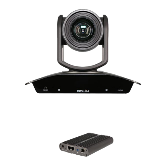
WHAT’S IN THE BOX Camera: HDBaseT Receiver (Not included with the camera, order separately) Accessories (Optional) -
Page 6: Overview
Overview Camera Version Hardware: HV:V.0C.0dejiklp.02.00S.03.A03 Software: SV:V0C0500S110401A09 HDBaseT Version: HV.V.D.0000cdjk.14.001.01.A03 Model Numbers This user guide is suitable for the following models: VCC-8-4K12S-SMB VCC-8-4K-BR (HDBaseT Model, not include with the camera, order separately) Features Resolution: 4K,1080P,720P Zoom: Optical 12X ... -
Page 7: Camera Diagrams
Camera Diagrams Camera 1. 12V DC Power Port Connect the supplied DC power adaptor and cord. 2. CVBS Video output 3. 3.5mm Audio Input 4. RS-422/485 Control Port RJ45 to RS422 extension cable is provided. (For more detail of extension cable see page15) 5. -
Page 8: Hdbaset Receiver
HDBaseT Receiver 18. LAN Port (RJ45, IP Pass-Thru) Connect network switch or router to this port for Dual Output HDMI+IP HDBaseT camera. NOTE: This HDBaseT receiver is not an IP video encoder. The LAN Port is the IP video extension for the IP video output on the camera side. -
Page 9: Remote Controller
Remote Controller 1. Power 2. Camera ID (Total 3) Selector 3. Preset Position (Total 6) Calling and Setting 4. PAN-TILT Pan and Tilt direction control HOME: Home position, Resolution reset 5. L/R Direction Set Left and right orientation setting 6. -
Page 10: System Configuration
System Configuration Connection When the camera is connected to a computer and joystick keyboard with a VISCA cable (cross type, RS-232), you can operate the camera with the computer and the joystick keyboard. When the camera is connected to a joystick keyboard a control cable (cross type, RS-422/485), you can operate the camera’s pan, tilt, zoom with the joystick keyboard. -
Page 11: Obtain Video Signal
In this connection configuration, HDMI cable, SDI video cable, data cable, Network cable is required. To obtain these third party components or accessories, consult the dealer where you bought your camera. Notes Use only the AC power adaptor (JEITA type4) supplied with the unit. Do not use any other AC power adaptor. -
Page 12: Camera Control Methods And System Configurations
Camera Control Methods and System Configurations This unit has multiple ways of controlling the camera and various system configuration capabilities using optional products. This section describes ways of controlling and typical system examples with the required components and usage of each system. 1. - Page 13 RS232 Connection 1. Set RS232 control method on Bottom Dip Switch. (See page 17). 2. Set Baud Rate on Bottom Dip Switch to the same as Baud Rate setting on the keyboard you are using. (See page 18). 3. Reboot the camera by turning it Off/On after the Bottom Dip Switch has been set up correctly. 4.
- Page 14 System Configuration C RS422 (VISCA) connection Set RS422 control method on Bottom Dip Switch (See page 17). Set Baud Rate on Bottom Dip Switch to the same as Baud Rate setting on the keyboard you are using. (See page 18). Reboot the camera by turning it Off/On after the Bottom Dip Switch has been set up correctly.
- Page 15 PELCO P/D Keyboard RS485 Connection Use PELCO P/D compatible keyboard. Use preset 95# on the keyboard to bring up/exit camera OSD menu. Use joystick and Button “OPEN” or “CLOSE” to navigate OSD menu. To operate keyboard, please refer to the user manual of the keyboard you are using. Control the camera using HDBaseT Receiver Set RS232 control method on Bottom Dip Switch(See page 17).
- Page 16 Note For control details, refer to Operating Instructions of control keyboard/station software. You need to match the communication speed between the camera and the joystick controller. You cannot use the RS-232 connections when using the RS422/485 connection. Operating Multiple Cameras Using RS-422/485 ...
-
Page 17: Bottom Dip Switch Settings
BOTTOM DIP SWITCH SETTINGS The bottom dip switch is for setting the camera configuration for following items: 1. Camera ID Address for RS-485 PELCO protocol 2. Video output / Video color space 3. RS-232 / RS-422/485 selection 4. RS-232 / RS-422/485 baud rate 5. - Page 18 4. RS-232 / RS-422 Baud Rate Setting RS-232 / RS-422 Baud Rate Setting 2400 bps 4800 bps 9600 bps (Default) 38400 bps Bit 1~4: Video resolution setting Bit 5~6: Reserve Bit 7~8: IR remote controller ID setting SW2 Factory default setting is: OFF OFF.ON.ON.OFF.OFF.OFF.OFF. 1.
-
Page 19: Adjusting And Setting With Menus
Adjusting and Setting with Menus About On-Screen Menus You can change various settings, such as shooting conditions and system setup of the camera, while observing menus displayed on a connected computer screen. This section explains how to read the on-screen menus before starting menu operations. The menu parameters may vary according to the different product model numbers. -
Page 20: Exposure Menu
EXPOSURE Menu The EXPOSURE menu is used to set the items related to exposure. MODE (Exposure Mode) FULL AUTO: The exposure is adjusted automatically using the sensitivity, electronic shutter speed, and iris. BRIGHT: Adjust the brightness level (LEVEL) manually. SHUTTER PRI: Shutter Priority mode. The exposure is adjusted automatically using the sensitivity and iris. -
Page 21: Picture Menu
PICTURE Menu The PICTURE menu is used to set the items related to the picture. SHARPNESS: Picture sharpness value ranges from 0 to 15. You can enjoy emphasized edge and high-resolution images. EFFECT: (Picture Effect) It consists of the following functions: Image effect from Off, B&W NOISE REDUCTION: Noise reduction - you can enjoy clearer images by removing unnecessary noise. - Page 22 Note You cannot set IR-RECEIVE to OFF when you operate the menu using the infrared remote controller. To set it to OFF, use the appropriate VISCA controller. DISPLAY INFO When this item is set to ON, the message of the camera configuration appears for about 3 seconds on the screen, after the camera is powered on or rebooted.
-
Page 23: Operation Using The Infrared Remote Controller
Operation Using the Infrared Remote Controller Pan/Tilt and Zoom Operation Panning and Tilting 1. Press the POWER switch. The camera will turn on and perform the pan/tilt reset operation automatically. 2. Press the arrow button to pan or tilt the camera. While checking the picture on the screen, press the desired arrow button. -
Page 24: Operating Multiple Cameras With The Infrared Remote Controller
Zooming Button [T] - Zoom-IN and [W] - Zoom-OUT. Button [F] – FAST mode. Press once and the LED turns red to activate the Fast Zoom Speed Mode, press again to go back to normal Zoom Speed mode. Note When you perform pan/tilt operation while the camera is in the telephoto mode, the moving speed of the image on the screen may be a little jerky. -
Page 25: Storing The Camera Settings In Memory - The Presetting Feature
Storing the Camera Settings in Memory — the Presetting Feature Memory (Preset) Using the preset function, 6 sets of camera shooting conditions can be stored and recalled. 6 sets of camera shooting conditions can be stored and recalled by using remote controller. Up to 128 presets via protocol programming. This function allows you to achieve the desired status instantly, even without adjusting the following items each time. -
Page 26: Menu Configuration
Menu Configuration The menus of the camera are configured as described below. For more details, refer to the pages in parentheses. The initial settings of each item are in bold. -
Page 27: Dimension
Dimension Unit: mm... -
Page 28: Installation
Installation Screw up the rack mount on HDBaseT Securing the HDMI cable on metal cable rack. -
Page 29: Specifications
Specifications... - Page 31 2082 TECHNOLOGY LLC BOLIN TECHNOLOGY...
Need help?
Do you have a question about the VCC-4KHDB-M-11142018 and is the answer not in the manual?
Questions and answers