
Related Manuals for Bolin Technology BC-9 Series


Summary of Contents for Bolin Technology BC-9 Series
-
Page 1: Ptz Camera
BC-9 Series 4K SDI+IP Dual Output PTZ Camera USER MANUAL Part One: Camera User Manual VERSION: BC-9-M-12262019 BC-9-4K12S-S6MN © 2020 Bolin Technology... -
Page 2: Table Of Contents
Contents IMPORTANT INFORMATION ..............................5 WHAT’S IN THE BOX ................................. 7 OVERVIEW ....................................8 FEATURES ....................................8 CAMERA DIAGRAMS ................................. 9 ..................................11 EMOTE ONTROLLER SYSTEM CONFIGURATION ............................... 12 ..................................12 ABLE EQUIREMENTS ..................................14 BTAIN IDEO IGNAL IN / OUT .................................... 14 UDIO SD C ....................................... - Page 3 NETWORK ....................................43 PAN TILT ZOOM M ................................. 44 SYSTEM MENU .................................... 44 ............................46 UTPUT VIDEO FORMAT SETTING FIRMWARE UPGRADE ................................46 MCU F ................................47 PGRADING IRMWARE ..............................47 PGRADING ENCODER FIRMWARE FPGA ................................47 PGRADING FIRMWARE ................................47 IDEO RESOLUTION UPGRADE OPERATION USING THE INFRARED REMOTE CONTROLLER .....................
-
Page 4: Operating Instructions
Before operating the unit, please read this manual thoroughly and retain it for future reference. Copyright Copyright 2015-2020 Bolin Technology all rights reserved. No part of this manual may be copied, reproduced, translated, or distributed in any form or by any means without prior consent in writing from our company. -
Page 5: Important Information
IMPORTANT INFORMATION Legal Notice Attention: To ensure account security, please change the password after your first login. You are recommended to set a strong password (no less than eight characters). Password login does not apply to some models that do not need password login. - Page 6 Do not drop the camera or subject it to physical shock. Do not touch sensor modules with fingers. If cleaning is necessary, use a clean cloth with a bit of ethanol and wipe it gently. If the camera will not be used for an extended period of time, put on the lens cap to protect the sensor from dirt.
-
Page 7: What's In The Box
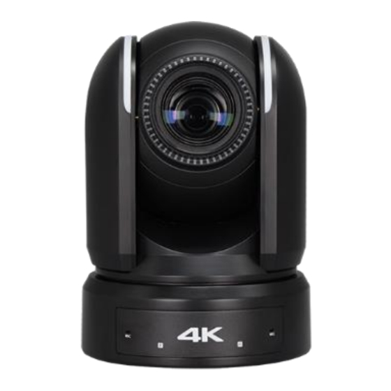
WHAT’S IN THE BOX Note: The camera color may be in white or black per the item that is purchased. Accessories (Optional) -
Page 8: Overview
Overview This user guide is suitable for the following models: BC-9-4K12S-S3MN/B (FHD, White) BC-9-4K12S-S3MN/W (FHD, Black) BC-9-4K12S-S6MN/B (4K, White) BC-9-4K12S-S6MN/W (4K, Black) BC-9-4K12S-LS-4K (FHD-4K Upgrade License) Features 1 Inch “Exmor R” CMOS sensor, Effective pixel number: 14.4 Megapixels. Resolution: Up to 2160P29.97, 1080P60, 1080i59.94;... -
Page 9: Camera Diagrams
Camera Diagrams... - Page 10 1. 12V DC Power Port Connect the supplied DC power adaptor and cord. 2. DIP Switch 3. Main HDMI1.4 (4K) Video Output 4. Sub HD HDMI Video Output Not available, for future AI Auto Tracking video output 5. 6G-SDI Video Output, Dual Link 3G-SDI Video Output combine with 6# 6.
-
Page 11: Remote Controller
Remote Controller 1. Power Power ON the camera to turn the camera in operation status. Power OFF the camera to turn the camera in standby status. When the camera is powered OFF, the camera turns to the back and would be on standby mode. -
Page 12: System Configuration
System Configuration Connection When the camera is connected to a computer and joystick keyboard with a VISCA cable (cross type, RS-232), you can operate the camera with the computer and the joystick keyboard. When the camera is connected to a joystick keyboard a control cable (cross type, RS-422/485), you can operate the camera’s pan, tilt, zoom with the joystick keyboard. - Page 13 Belden 4694R/RG-6/U is a suitable cable to transmit broadcast-quality video: SDI video cable: 3G-SDI Belden1694A/5CFB is a suitable cable to transmit broadcast-quality video: Conductor: Stranding Material Nominal Diameter Solid Bare Copper 0.04 in. Shield Material Type Layer Material Coverage Tape Aluminum / Polyester / Aluminum 100% Braid...
-
Page 14: Obtain Video Signal
Obtain Video Signal The camera can simultaneously have SDI, HDMI, IP / NDI video outputs. HDMI Video signal 1. Connect the camera to a UHD Monitor/TV using HDMI cable. 2. Turn on the camera, video will display on the monitor after running initializing. 3. - Page 15 Currently, the following Micro SD cards are supported: Camera Initial setting status Information Information of the camera initial setting status will display for 5 Camera Status Info Display seconds. PELCO ID 1. Camera PELCO ID for RS-485 control VISCA ID 2.
-
Page 16: Camera Control Methods And System Configurations
Camera Control Methods and System Configurations This unit has multiple ways of controlling the camera and various system configuration capabilities using optional products. This section describes the ways of controlling and typical system examples with the required components and usage of each system. 1. - Page 17 You can make RS232 connection cable if you have the following applications: Use extension cables included RJ45 to RS232 8 pin Mini Din adaptor to make RS232 connection for your control device. 10. Use extension cables included RJ45 to RS422/232 Phoenix terminal contact adaptor to make RS232 connection for your control device.
-
Page 18: Use Rs-422(Visca) / Rs485 (Pelco P/D)
12. How to make RS232 Daisy Chain multiple camera connection with standard RS232 serial port controller as below: Use RS-422(VISCA) / RS485 (PELCO P/D) You can use RS-422/485 port connect to optional controllers, such as joystick control keyboard, control PC station, to operate the camera. - Page 19 SONY Keyboard RS422 Connection 10. How to make RS422 connection and RS422 Daisy Chain multiple cameras connection with Non-Sony controller as below: VISCA (Non-Sony) Keyboard RS422 Connection 11. Use extension cables RJ45 to RS422 Phoenix connecter adaptor included to make RS422 connection for your control device.
- Page 20 12. Or you can use CAT5/6 T-568B Standard Ethernet cable direct connect between the camera and the controller to make RS422 connection by following the pin definition below: 13. How to make RS422 Daisy Chain multiple camera connection with RS422 standard serial port controller:...
-
Page 21: Pelco P/D Keyboard Rs485 Connection
PELCO P/D Keyboard RS485 Connection NOTE: Use RS422 ports for RS485 connection. Only use TX+ and TX- for RS485 connection. Set RS422 control method on Bottom Dip Switch. Set Baud Rate on Bottom Dip Switch to the same as Baud Rate setting on the keyboard you are using. ... - Page 22 How to make RS485 multiple cameras connection with RS485 standard serial port controller: Note For RS-232 VISCA control, this unit supports daisy chain connection for using multiple cameras. For control details, refer to Operating Instructions of control keyboard/station software. ...
-
Page 23: Visca Over Ip Control
VISCA over IP Control With VISCA over IP function, you can control the camera using VISCA protocol on a controller equipped with IP communication capabilities via LAN. The communication specifications of VISCA over IP are followings: Interface: RJ-45 10/100M ... -
Page 24: Optional Video Output Cards
Optional Video Output Cards 9 Series 4K PTZ camera has two optional video output cards: HDBaseT video output Optical SDI output HDBaseT Video Output Card... -
Page 25: Hdbaset Receiver
HDBaseT Receiver 1. LAN Port (RJ45, IP Pass-Thru) Connect network switch or router to this port for Dual Output HDMI+IP HDBaseT camera. NOTE: This HDBaseT receiver is not an IP video encoder. The LAN Port is the IP video extension for the IP video output on the camera side. -
Page 26: Hdbaset Connection
HDBaseT Connection Unscrew the cover and remove the cover piece from the back panel slot, insert the HDBaseT card into the slot. Make sure the card is completely inserted in the place properly. Use HDBaseT Receiver to obtain HDMI 4K / HD Video signal 1. - Page 27 Via HDBaseT, you can use IR remote controller to control the camera from the remote side that is up to 100 meters away. RS232/RS422 Control Must set the camera in RS232 control method on Bottom Dip Switch. Set Baud Rate on Bottom Dip Switch to the same as Baud Rate setting on the keyboard you are using. Reboot the camera by turning it Off/On after the Bottom Dip Switch has been set up correctly.
-
Page 28: Rs232/422 Connection Between The Hdbaset Receiver And The Controller
RS232/422 Connection between the HDBaseT receiver and the controller: To make the RS232/RS422/RS485 control cable connection between the HDBaseT receiver and the controller: Use CAT5/6 T-568B Standard Ethernet cable direct connect between the camera/HDBaseT Receiver and the controller to make RS232/RS422/485 connection by following the pin definition below: RS232: Make RJ45 connector for HDBaseT Receiver RS232 port as following: RS422: Make RJ45 connector for HDBaseT Receiver RS422 port as following: RS485: Make RJ45 connector for HDBaseT Receiver RS485 port as following:... - Page 29 NOTE: Use RS422 ports for RS485 connection. Only use TX+ and TX- for RS485 connection. The RS232/RS422 serial port connection on controller side, please refer to the user guide of the controller. Use extension cables included to connect the RS232/RS422/RS485 control to the controller: RJ45 to RS232 extension adapter cable.
- Page 30 RS422 Connection: RJ45 to RS422/232 Phoenix terminal contact adaptor: Use extension cables included to make RS422 connection for your control device. Make the RS422 connection as following pinout definition instruction: If you have more than one HDBaseT receivers to make multiple camera connection for RS422 daisy chain control ...
- Page 31 RS422 Daisy Chain multiple camera connection via HDBaseT receivers: RS485 Daisy Chain multiple camera connection via HDBaseT receivers: Operating Multiple Cameras Using RS-422/485 Using RS-422 (VISCA), you can connect up to 7 cameras. Using RS-485 (PELCO), you can connect up to 255 cameras. ...
-
Page 32: Optical Video Output Card
Optical Video Output Card... - Page 33 Optical video card Connection Unscrew the cover and remove the cover piece from the back panel slot, insert the optical video card into the slot. Make sure the card is completely inserted in the place properly. SFP Fiber Optical Module: Laser Unit: Single-mode 1,310nm DFB-LD transmitter and PIN receiver Complaint with MSA SFP+ Specification SFF-8402.
-
Page 34: Tally Light Gpi I/O Connection
Tally Light GPI I/O connection GPI connection with RS422 VISCA control connection GPI connection with VISCA OVER IP control connection How to make the connection with BOLIN products Please see the User Guide “BOLIN Camera and Keyboard Controller Connection” that you can download it at www.bolintechnology.com product pages. -
Page 35: Dip Switch Settings
DIP SWITCH SETTINGS The Dip switch is for setting the camera configuration for following items: 1. Camera ID Address for VISCA protocol 2. Video color space 3. RS-232 / RS-422 control method selection 4. RS-232 / RS-422 baud rate selection Setting of the DIP Switches Turn off power to the camera before changing the DIP switch settings. - Page 36 Setting of the back panel Rotate DIP Switches The Rotate Dip Switch is for setting video format. Use small screw driver to turn the switch, the arrow points to the Numbers or the Letters. The video format that the Number or Letter stands for refer to the video format as the chart following: Numbers &...
-
Page 37: Adjusting And Setting With Menus
Adjusting and Setting with Menus About On-Screen Menus You can change various settings, such as shooting conditions and system setup of the camera, while observing menus displayed on a connected computer screen. This section explains how to read the on-screen menus before starting menu operations. The menu parameters may vary according to the different product model numbers. -
Page 38: Exposure Menu
When you are operating the menu using the infrared remote controller, you cannot set IR- RECEIVE in the SYSTEM menu to OFF. To set IR- RECEIVE to OFF, use the appropriate VISCA command. EXPOSURE Menu The EXPOSURE menu is used to set the items related to exposure. MODE (Exposure Mode) EXPOSURE MENU: FULL AUTO FULL AUTO: Iris, Gain and Shutter Speed can... - Page 39 When you select one from various exposure modes, some of the following setting items that are required for the selected mode will appear. GAIN: Select the gain from the following: 0dB, 3dB, 6dB, 9dB, 12dB, 15dB, 18dB, 21dB, 24dB, 27dB, 30dB, 33dB, 36dB GAIN LIMIT: The gain limit can be set at Full Auto, Iris Priority, Shutter Priority mode.
-
Page 40: White Balance Menu
enable exposure compensation. When you set EX-COMP to ON, LEVEL appear and you can select the exposure compensation level from the following: –10.5, –9, –7.5, –6, –4.5, –3, –1.5, 0, +1.5, +3, +4.5, +6, +7.5, +9, +10.5 If you set the level to 0, exposure compensation will be disabled. Level +10.5 is the brightest and –10.5 is the darkest compensation value. -
Page 41: Detail Menu
NOTE: When you select the OPW (One Push White Balance) Perform the following operations: 1. Place an image of white subject (For example: A piece WHITE BALANCE MENU of white paper) in the center of the screen. WB MODE 2. Press the HOME button of the infrared remote controller. The one-push white balance adjustment is activated. -
Page 42: Picture Menu
H/V BALANCE: You can choose the ratio for horizontal and vertical contour correction signal elements. Choose a value from –2 to 0 to +2. When you choose a higher value, the horizontal contour correction elements become greater compared to the vertical elements. B/W BALANCE: You can adjust the balance between contours in black on the low brightness side of the spectrum and contours in white on the high brightness side. -
Page 43: Gamma
When the image stabilizer function is set to ON, you can obtain the image with less screen blur caused by shaking. The correction effect can be achieved at the vibration frequency around 10 Hz. The image stabilizer function uses the digital zoom method. Although there are changes in the angle of view and resolution, the sensitivity is maintained. -
Page 44: Pan Tilt Zoom Menu
PAN TILT ZOOM Menu The PAN TILT ZOOM menu is used to select the PAN TILT ZOOM MENU pan/tilt/ zoom mode. DIGITAL ZOOM EXPOSURE DIGITAL ZOOM: ZOOM RATIO OSD WHITE BALANCE Set to DIGITAL ZOOM ON, 12X digital zoom (with AF SENSITIVITY NORMAL DETAIL... - Page 45 When this item is set to ON, the message of the camera configuration appears for about 10 seconds on the screen, after the camera is powered on or rebooted. PRESET MEMORY: This feature allows you to save the image parameter to PRESET memory, turn it on to save most image parameters like as picture, white balance, exposure, focus mode, zoom positions when you call the preset.
-
Page 46: True Dual Output Video Format Setting
The firmware upgrade process is intended to be performed under the supervision of a BOLIN-Authorized repair technician. For assistance with this, please contact your authorized BOLIN Technology dealer, installer, or integrator. BOLIN Technology Technical Support can also be reached for assistance with this process... -
Page 47: Upgrading Mcu Firmware
Upgrading MCU Firmware MCU Firmware can be upgraded by following these steps: 1. Load the .bin file onto a flash drive (Formatted as FAT32), and name the file “HD20.bin” 2. With the camera powered off, insert the flash drive to the USB port on the back panel of the camera 3. -
Page 48: Operation Using The Infrared Remote Controller
Operation Using the Infrared Remote Controller Pan/Tilt and Zoom Operation Panning and Tilting 1. Press the POWER switch. The camera will turn on and perform the pan/tilt reset operation automatically. 2. Press the arrow button to pan or tilt the camera. While checking the picture on the screen, press the desired arrow button. -
Page 49: Operating Multiple Cameras With Infrared Remote Controller
When the STANDBY lamp is blinking If the camera is moved forcibly, or a finger or other object interferes with camera movement, the camera may fail to memorize the pan/tilt position. Press the PAN-TILT RESET button to reset the pan/tilt position. Zooming Button (Slow Zoom) [T] - Zoom-IN and [W] - Zoom-OUT slowly Button (Fast Zoom) [T] - Zoom-IN and [W] - Zoom-OUT quickly... -
Page 50: Storing The Camera Settings In Memory - The Presetting Feature
Storing the Camera Settings in Memory — the Presetting Feature Memory (Preset) Using the preset function, 9 sets of camera shooting conditions can be stored and recalled. 9 sets of camera shooting conditions can be stored and recalled by using remote controller. Up to 128 presets via protocol programming. -
Page 51: Adjusting The Camera
Adjusting the camera Adjusting the camera, including camera image parameter (Gain, Color, Contrast, White Balance (Red & Blue), Black Level), camera speed (Pan/Tilt speed, zoom speed and preset speed), as well as Freeze, Back Light and One Push White Balance. Gain-Adjust Gain Press Gain button, the Gain button light will on, then press “+”... - Page 52 AI Feature Mode This IR Remote Controller can be used for BOLIN AI (Auto Framing/Auto Tracking) camera, we can set this IR controller to AI mode, to set up AI feature quickly. AI Button: Press AI button, the IR controller will switch to AI mode. Zoom: AI Feature, it is available when AI button is pressed.
-
Page 53: Menu Configuration
Menu Configuration The menus of camera are configured as described below. The initial settings of each item are in bold. SDI Menu Configuration... -
Page 56: Dimensions
Dimensions Unit: mm... - Page 57 2082 TECHNOLOGY LLC BOLIN TECHNOLOGY...
Need help?
Do you have a question about the BC-9 Series and is the answer not in the manual?
Questions and answers