
Related Manuals for Bolin Technology SD500 Series


Summary of Contents for Bolin Technology SD500 Series
- Page 1 SD500 SERIES IP SPEED DOME CAMERA HD/4K/STARLIGHT USER MANUAL VERSION: SD5IP-M-11142018 © 2018 Bolin Technology...
-
Page 2: Table Of Contents
Contents PART ONE: PTZ CAMERA USER MANUAL ............................ 4 IMPORTANT INFORMATION ............................... 4 OVERVIEW ....................................7 ......................................7 EATURES WHAT’S IN THE BOX..................................8 ..................................8 CCESSORIES PTIONAL CAMERA DIAGRAMS .................................. 9 TAIL-CABLE ....................................10 INSTALLING YOUR CAMERA ..............................12 ........................ - Page 3 ................................. 42 ETTING THE YSTEM ....................................43 ETTING ERVERS ..............................43 ERIAL ONFIGURATION MAINTENANCE ..................................46 ..................................46 PGRADING THE EVICE ..................................46 ESTARTING THE YSTEM ........................47 MPORTING AND XPORTING YSTEM ONFIGURATION ............................... 47 OLLECTING IAGNOSTIC NFORMATION & F .............................
-
Page 4: Part One: Ptz Camera User Manual
Before operating the unit, please read this manual thoroughly and retain it for future reference. Copyright Copyright 2015-2016 Bolin Technology all rights reserved. No part of this manual may be copied, reproduced, translated, or distributed in any form or by any means without prior consent in writing from our company. - Page 5 The contents of this document are subject to change without prior notice. Updates will be added to the new version of this manual. We will readily improve or update the products or procedures described in the manual. Best effort has been made to verify the integrity and correctness of the contents in this document, but no statement, information, or recommendation in this manual shall constitute formal guarantee of any kind, expressed or implied.
- Page 6 WARNING!: Indicates a hazardous situation which, if not avoided, could result in bodily injury or death. CAUTION!: Indicates a situation which, if not avoided, could result in damage, data loss or malfunction to product. NOTE: Indicates useful or supplemental information about the use of product. Safety Information WARNING! Installation and removal of the unit and its accessories must be carried out by qualified personnel.
-
Page 7: Overview
Overview This user guide is suitable for the following models: If the model numbers that have following letter included in the end, means some extra features included: 1. A - with Full Functionality Tail-Cable with Alarm input and output, etc. 2. -
Page 8: What's In The Box
WHAT’S IN THE BOX Accessories- Optional... -
Page 9: Camera Diagrams
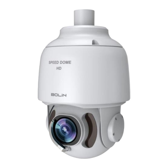
Camera Diagrams Camera 1. IR LED Illuminator 2. Lens 3. Rain Wiper BL-PP80 80w PoE Power Injector (Optional) 1. Data/Power Output (Connect to the specific PoE camera, Power Comsumption:80w, port of speed: 100/1000Mbps adaptive) 2. Data in (Connect to network switch) 3. -
Page 10: Tail-Cable
All cables are tagged to indicate their functions separately. The cables available may vary with the product model. There are two types of Tail-Cable available for SD500 series PTZ camera. 1. Type A-Cable: Full function cable with audio and alarm 2. - Page 11 N-Cable Connection A-Cable Connection NOTE: Use water proof / IP67 rated junction box/ connection box to protect the RJ45 and other connections. A water proof RJ45 connector is available on some models.
-
Page 12: Installing Your Camera
Installing Your Camera The following diagrams are for your reference only. See the actual product to mount your camera. Check Camera Components and Installation Conditions Before mounting your camera, check the device model number and included contents against the packing list to ensure components are complete. - Page 13 For PoE power, you must use Bolin 80W Power PoE Injector: model BL-PP80. It provides High PoE power up to the PTZ camera. Connect this PoE injector to a network switch and then run Ethernet cable for data transmission and power up the PoE PTZ camera (Specific model: EX1000 & SD500 Series) for distance up to 100 meters. NOTE: ...
-
Page 14: Mounting The Camera
Mounting the Camera NOTE: When mounting the camera, please install the bracket adapter to the bracket first and then mount the camera to the bracket. Tighten all the screws to hold the camera securely. For waterproofing, apply sealant between the dome and the bracket, wall veneer slits, and leading-out holes of the wall. -
Page 15: Accessing Your Camera
Accessing Your Camera For camera models with IP output, you can manage and control through the web interface from a PC. System Requirements for Your PC Operating System: Microsoft Windows 8/Windows 7/Windows XP (32-bit or 64-bit). Microsoft Windows 7 (32-bit) is recommended. -
Page 16: Part Two: Network Camera User Manual
Part Two: Network Camera User Manual Network Connection Before accessing a network camera (also known as IP Camera or IPC) from a PC, you need to connect the network camera to the PC directly with a network cable or via a switch or router. Use a Shielded Twisted Pair (STP) cable to connect the network interfaces of the network camera and the PC. - Page 17 Add the IP address as a trusted site Follow the illustrations bellow: http://192.168. 0.13 Clear the check NOTE: NOTE: The IP address 192.168.0.13 in this example is the default IP address. Please replace it with the actual address of your camera if it has been changed. Modify user access control settings (Optional) Before you access the camera, follow the steps to set User Account Control Settings to never notify.
-
Page 18: Logging In To The Web Interface
Logging In to the Web Interface The default static IP address of the camera is 192.168.0.13, and the default subnet mask is 255.255.255.0. DHCP is turned on by default. If a DHCP server is used in the network, the IP address of your camera may be assigned dynamically, and you need to use the correct IP address to log in. -
Page 19: Introduction To The Web Interface
Introduction to the Web Interface By default, the live view window is displayed when you are logged in to the Web interface. The following shows an example. Initial Configuration After you log in to the device, please perform the following initial configuration. 1. -
Page 20: Configuring Parameters
Configuring Parameters Local Parameters Set local parameters for your PC. NOTE: The local parameters may vary with models, please see the actual Web interface for details. Select Setup to go into IP camera setting up menu. 1. Select Setup > Common > Basic Info. It displays the basic information of the camera. -
Page 21: Network Configuration
example, 2 minutes. ii. Subsection By Size: Size of each recording file stored on the computer. For example, 5M. b. When Storage Full i. Overwrite Recording: When the assigned storage space on the computer is used up, the camera deletes the existing recording files to make room for the new recording file. ii. -
Page 22: Pppoe
PPPoE If the camera is connected to the network through Point to Point over Ethernet (PPPoE), you need to select PPPoE as the IP obtainment mode. 1. Click Setup > Network > TCP/IP. 2. Select PPPoE from the IP Obtain Mode drop-down list. 3. - Page 23 1. Click Setup > Network > FTP. 2. Configure the IP address, port number of the FTP server, the username and password of the upload account, enable Upload Images and Overwrite Storage, and then set the overwrite image threshold. 3. Click Save. E-Mail After the configuration of E-mail, when alarms are triggered, you will be able to send messages to the specified E- mail address.
-
Page 24: Image Configuration
Image Configuration Image Adjustment NOTE: The image parameters displayed and value ranges allowed may vary with camera model. For the actual parameters and value ranges of your camera, see the Web interface. You may move the sliders to adjust settings or enter values in the text boxes directly. - Page 25 parameters for the scene. ii. The camera switches the current scene automatically when Enable Auto Switching is selected. B. Scene Name a. Name of the current scene. The device provides several preset scene modes. When you select a scene, the corresponding image parameters are displayed. You can adjust image settings according to actual needs.
- Page 26 1. Click Setup > Image > Image and then click Image Enhancement. 2. Use the sliders to change the settings. You may also enter values directly. The following table describes some major parameters. A. Brightness a. Set the degree of brightness of images. B.
- Page 27 i. You can set this parameter only when Exposure Mode is not set to Shutter Priority and when Image Stabilizer is disabled. D. Slowest Shutter a. Set the slowest shutter speed that the camera can use during exposure. i. You can set this parameter only when Slow Shutter is set to On. E.
- Page 28 configure other parameters. The Web interface of certain network camera model is displayed as follows. Follow steps below to configure the illumination parameters. 2. Select the correct IR control mode and set the parameters. The following table describes some major parameters. A.
- Page 29 b. Manual Focus: Manually adjust camera focus as required. c. One-Click Trigger: The camera is triggered to focus once when rotating, zooming or going to a preset. d. One-Click Trigger (IR): In a low light condition such as during night hours or in a dark house, this focus mode achieves better effects with the IR light turned on.
- Page 30 Configuring Iris and Lens NOTE: This function is only supported by certain network box camera types, please see the actual model for details. When using the lens with P-Iris control mode that supports Z/F function, connect the iris control cable to the Z/F port of the camera.
- Page 31 Position: Click the desired box in the Live View area. After the cursor shape is changed, click and hold the button to move the box to the desired position. To set the position precisely, use the X and Y coordinates under Overlay Area. Overlay OSD Content: The drop-down list ...
-
Page 32: Audio And Video Configuration
Audio and Video Configuration Video Configuration You can set video parameters that your camera supports and view the current status of BNC output. If available, you may also enable sub-stream and third stream as required. NOTE: This function may vary with models. Only some camera models support the third stream. To determine if your camera supports this function, see the Web interface. -
Page 33: Video Format
Video Format 1. You can select the video format from Capture Collect Mode dropdown menu. 2. The selection of the video format is different on HD, 4K resolution models. 3. Click Save after you make the selection. NOTE: Changing the video format/capture mode will restore the default encoding setting and causes the device to restart. -
Page 34: Roi
When Region of Interest (ROI) is enabled, the system ensures image quality for ROI first if the bit rate is insufficient. NOTE: This function may vary with models, please see the actual Web interface for details. 1. Click Setup > Video & Audio > ROI. 2. -
Page 35: Alarm Configuration
1. Click Setup > Video & Audio > Media Stream > RTSP Multicast Address. 2. Set the multicast address (224.0.0.0 to 239.255.255.255) and port number (0 to 65535). 3. Click Save. Alarm Configuration NOTE: This function may vary with models, please see the actual Web interface for details. ... - Page 36 2. In the Detection Area, click to add a new detection area. To delete a detection area, click 3. Click and drag the mouse to set a detection area. 4. Set the detection sensitivity, object size, and history for the camera to decide whether to report a motion detection alarm.
- Page 37 a third-party device. c. PTZ to Preset i. Select the check box and set the preset linked to motion detection alarm. 1. Make sure you have set presets. Otherwise, you cannot set this parameter. For details about how to set a preset, see Setting Presets. 2.
- Page 38 1. Click Setup > Events > Common Alarm > Audio Detection. 2. Select Enable for Audio Detection, select a detection type and set the difference or threshold. To disable audio detection, clear the Enable check box. The following table describes some major parameters. a.
-
Page 39: Memory Card Storage
here, so that the camera can receive alarm information from the third-party alarm input device. Set actions to be triggered by an input alarm and the plan. For the detailed steps, see the descriptions of alarm-triggered actions in Configuring Motion Detection Alarm . Click Save. - Page 40 2. Enable memory card storage and modify the settings as required. The following table describes some major parameters. a. Storage Medium i. Storage resource type. 1. To format the memory card, disable the storage function for the card first. Then Click Format and then click OK to confirm the operation.
-
Page 41: System Maintenance
System Maintenance NOTE: This function is not supported by some models, and may vary with models, please see the actual model for details. Security User Management There are two types of users in the system: Administrator: referred to as “admin” in this manual. The default name of the administrator is admin, which cannot be modified. -
Page 42: Setting The System Time
ARP Binding This function can protect the camera from ARP attacks. When the camera visits an IP of another network segment via a gateway, it can communicate only with the MAC address binding to the gateway address in the same segment. Click Setup >... -
Page 43: Setting Servers
Select Enable for NTP, and then enter the IP address of the NTP server and the camera's sync interval with the NTP server. Click Save. The camera will periodically synchronize time with the NTP server. Setting Servers If the camera is managed by a central server, you need to configure the server related parameters. CAUTION: ... - Page 44 PTZ control To control a PTZ camera through a third-party device, you need to set Port Mode to PTZ Control. By sending PELCO-D compliant PTZ control commands through the RS485 port, you can control the PTZ camera without using the PTZ control panel. 1.
- Page 45 To display information from the third-party device on the OSD, you need to select OSD as the port mode. The camera receives information from the third-party device through the RS485 serial port, translates the received information, and then displays it on the OSD. NOTE: To enable the camera to correctly translate information received from the third-party device, make sure that the information sent by the third-party device through the serial port complies with the data format specified by our...
-
Page 46: Maintenance
NOTE: Serial Port: The wiper is controlled through PELCO-D instructions. Please set the PTZ protocol to PELCO-D. Normally Open/Closed: The wiper is controlled through alarm input/output settings, including normally open and normally closed. Enable Wiper: This function is available only in alarm input/output mode. Viewing Device Status You can view the current status of your camera. -
Page 47: Importing And Exporting System Configuration File
Importing and Exporting System Configuration File Export the current configurations of the camera and save them to the PC or an external storage medium. You can also quickly restore configurations by importing backup configurations stored on the PC or an external storage medium back to the camera. -
Page 48: Live View
Click Setup > System > Maintenance. Configure Minimum Focus Distance under Focus. Click OK. Max. Zoom Ratio This section provides the zoom capabilities, which is digital zoom capabilities. Click Setup > System > Maintenance. Configure zoom ratio in dropdown menu. The smallest number is the camera optical zoom range. Click OK. -
Page 49: Live View Toolbar
Live View Toolbar NOTE: The supported live view operations may vary with camera model. For the operations that your camera supports, see the Web interface. 1. Play/stop live video. 2. Turn On/Off speaker. 3. Adjust the output volume for the media player on the PC. 4. -
Page 50: Viewing Certain Area Of Images
Viewing Certain Area of Images Digital zoom and 3D positioning allow you to get more details of certain part of images. Digital zoom enlarges an image with loss in image quality, while 3D positioning enlarges an image without. Using 3D Positioning NOTE: ... -
Page 51: Ptz Control
Select the date from the calendar. Click Query. Under Results, double-click the time period to start playing the recording. Download Click Setup > Storage > Record Download. Search for video within a specified period. The results will be shown in a list. Select your video and click Download. -
Page 52: Setting Patrol By Presets
Setting Patrol by Presets Setting Presets On the Preset tab, you can manage presets or perform certain control operations to the PTZ camera. For more details, see PTZ Control Toolbar. Add a preset 1. On the Live View page, click Preset on the control panel. - Page 53 Add a patrol route On the Live View page, click Patrol on the control panel. Click . On the Add Patrol page, enter the route ID and name, and then click Add to add a patrol action. Use the buttons to adjust the sequence of the actions.
- Page 54 Click Submit. Start a patrol route After you have added a patrol route, select the patrol route to start patrol. On the Live View page, click Patrol on the control panel. Click for the patrol route you want to start. Edit a patrol route On the Live View page, click Patrol on the control panel.
-
Page 55: Appendix A Glossary
Appendix A Glossary Acronym Description Address Resolution Protocol Constant Bit Rate Domain Name Service DDNS Dynamic Domain Name Service DHCP Dynamic Host Configuration Protocol Daylight Saving Time File Transfer Protocol Group Of Pictures Graphical User Interface HTTPS Hyper Text Transfer Protocol over SSL Internet Explorer IMOS IP Multimedia Operation System... -
Page 56: Specifications
Specifications HD Models... -
Page 57: Starlight Models
STARLIGHT Models... -
Page 58: 4K Models
4K Models... -
Page 59: Dimensions
Dimensions S-Type Unit: mm... - Page 60 L-Type Unit:mm...
-
Page 61: Model: Bl-Pp80 (80W Poe Power Injector)
Model: BL-PP80 (80w PoE Power Injector) Unit:mm... - Page 62 2082 TECHNOLOGY LLC BOLIN TECHNOLOGY...
Need help?
Do you have a question about the SD500 Series and is the answer not in the manual?
Questions and answers