
Related Manuals for Bolin Technology KBD-1010


Summary of Contents for Bolin Technology KBD-1010
- Page 1 Bolin PTZ camera Bolin Keyboard Controller Wire Connection Guide USER MANUAL 1, 7, 8 Series Camera HDBaseT Receiver KBD-1010 VERSION: UG-CKC-12222018 © 2018 Bolin Technology...
-
Page 2: Table Of Contents
Contents IMPORTANT INFORMATION ..............................3 KEYBOARD DIAGRAMS ................................6 KBD-1010 ...................................... 6 ....................................6 CREEN ....................................... 7 EYBOARD ....................................8 UNCTION SYSTEM OVERVIEW .................................. 9 ................................. 9 ROSS ROTOCOL ONTROL CONNECTION ..................................10 ......................................10 OWER ............................... 11 ONNECTOR INOUT EFINITION .................................... -
Page 3: Important Information
Before operating the unit, please read this manual thoroughly and retain it for future reference. Copyright Copyright 2018 Bolin Technology all rights reserved. No part of this manual may be copied, reproduced, translated, or distributed in any form or by any means without prior consent in writing from our company. - Page 4 Maintenance Precautions: Ensure that no moisture or liquid comes into contact with any surface of the keyboard, as liquid may damage the functions of the keyboard. Keep dust the RJ-45 ports free from dust and moisture Only use the original, uncut (not spliced) power supply that is included with the keyboard Regulatory Compliance FCC Part 15 This equipment has been tested and found to comply with the limits for digital device, pursuant to part 15 of the FCC...
- Page 5 This section is as a sub-portion of the KBD-1010 Keyboard Controller 1/7/8 Series Camera HDBaseT Receiver user guides for the cases where the KBD-1010 keyboard controller is being used to control Bolin cameras. For the full operation guide, please refer to the product user guide, available at https://bolintechnology.com...
-
Page 6: Keyboard Diagrams
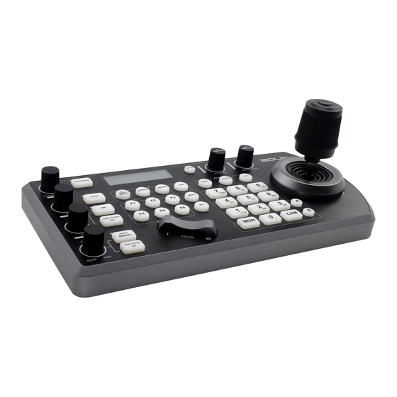
Keyboard Diagrams KBD-1010 1. Power Button Power on / Power off the keyboard 2. 12V DC Power Port, wide range input tolerance from 5V-48VDC Connect the supplied DC power adaptor and cord 3. Firmware Interface Button Engages firmware update mode on the keyboard 4. -
Page 7: Keyboard
Keyboard 1. White Balance, (Auto, Manual) Press once for Auto Press again to activate manual adjustments 2. Lock – locks all image adjustment buttons and dials 3. Exposure, (Auto, Iris PRI, Shutter PRI) 4. IP Interface Buttons – used to interact with IP cameras 5. -
Page 8: Junction Box
Junction Box 1. RJ45 port for connection between Junction Box and The Keyboard Controller 2. 12V DC Power Port Connect the supplied DC power adaptor and cord 3. Junction Box body 4. Terminal Contact connection for RS422 or RS232 5. RJ45 port for connection between Junction Box and The camera Use Network cable to connect directly 6. -
Page 9: System Overview
System Overview Cross-Protocol Mix Control Figure 1 - When the junction box is powered, it will provide power to the keyboard via any port that it is connected to --RS232, IP, RS422(A), RS422(B). No additional power supply is required for the keyboard a powered junction box is being used. Please Note regarding Serial Control protocols (RS422/RS485 and RS232): ... -
Page 10: Connection
Connection The controller supports serial RS232/RS422 and IP Cross protocol mix-control. It allows you to use RS232/RS422/IP control on one controller to control cameras (Protocol support: VISCA, PELCO D/P, ONVIF, VISCA over IP, CGI*) in a single system. IP port to network switch ... -
Page 11: Connector Pinout Definition
Figure 2 - Power supply is required at EITHER the keyboard OR the Junction Box. If the junction box is powered, no additional power supply is needed for the keyboard, as the junction box will provide power to the keyboard via the control port Connector Pinout Definition... -
Page 12: Ip Connection
IP connection... -
Page 13: Connection With Bolin Camera
Connection with Bolin Camera This User Guide is suitable for following Bolin cameras:... -
Page 14: Serial Port Connection
Serial Port Connection RS232 connection with Bolin Camera Follow the diagram below for the following options:... -
Page 18: Rs422 Connection With Bolin Camera
RS422 connection with Bolin Camera Follow the diagram below for the following options:... -
Page 22: Rs485 Connection With Bolin Camera
RS485 connection with Bolin Camera Follow the diagram below for the following options: ... - Page 23 ...
-
Page 27: Ip Control
IP Control Use ONVIF IP Control:... -
Page 28: Use Visca Over Ip Control
Use VISCA OVER IP Control: Cross-Protocol Mix Control... -
Page 29: Tally Light Gpi I/Oconnection
Tally Light GPI I/O connection GPI connection with RS422 VISCA control connection GPI connection with VISCA OVER IP control connection... - Page 30 www.bolintechnology.com...
- Page 31 2082 TECHNOLOGY LLC BOLIN TECHNOLOGY...
Need help?
Do you have a question about the KBD-1010 and is the answer not in the manual?
Questions and answers