
Related Manuals for Bolin Technology VCC-8-4K20S-3SM


Summary of Contents for Bolin Technology VCC-8-4K20S-3SM
- Page 1 4K PTZ Camera USER MANUAL VERSION: VCC-4K12S-M-12292018 VCC-8-4K20S-3SM © 2018 Bolin Technology...
-
Page 2: Table Of Contents
Contents IMPORTANT INFORMATION ..............................3 WHAT’S IN THE BOX ................................. 5 OVERVIEW ....................................6 ..................................... 6 ODEL UMBERS FEATURES ....................................6 CAMERA DIAGRAMS ................................. 7 ......................................7 AMERA ..................................8 EMOTE ONTROLLER ......................................8 OWER ..................................9 ABLE EQUIREMENTS SYSTEM CONFIGURATION ............................... 10 .................................... -
Page 3: Important Information
Before operating the unit, please read this manual thoroughly and retain it for future reference. Copyright Copyright 2015-2018 Bolin Technology All rights reserved. No part of this manual may be copied, reproduced, translated, or distributed in any form or by any means without prior consent in writing from our company. - Page 4 models. Please see the actual product for details. Due to uncertainties such as physical environment, discrepancy may exist between the actual values and reference values provided in this manual. Use of this document and the subsequent results shall be entirely on the user’s own responsibility. Safety Information WARNING! Installation and removal of the unit and its accessories must be carried out by qualified personnel.
-
Page 5: What's In The Box
WHAT’S IN THE BOX Accessories (Optional) -
Page 6: Overview
Overview Model Numbers This user guide is suitable for the following models: VCC-8-4K20S-3SM Features Resolution: 4K,1080P,720P Zoom: Optical 20X, Digital 12X. SRZ Feature: Up to 30X in 4K and 40X in FHD via Super Resolution Zoom ... -
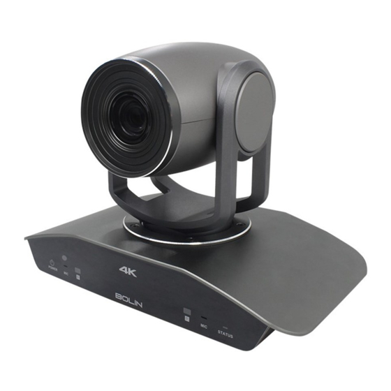
Page 7: Camera Diagrams
Camera Diagrams Camera 1. 12V DC Power Port Connect the supplied DC power adaptor and cord. 2. Reset Button Reset the image resolution to default setting (1080P59.94). 3. RS-232 Control Port The control cable is not included. The RS-232 cable usually is provided by controller. 4. -
Page 8: Remote Controller
Remote Controller 1. Power Power ON the camera to turn the camera in operation status. Power OFF the camera to turn the camera in standby status. When the camera is powered OFF, the camera turns to the back and would be on standby mode. ... -
Page 9: Cable Requirements
Cable Requirements Network Cable: 10/100 Mbps Ethernet CAT 5/5E/6 UTP cables are applicable to the ANSI/EIA/TIA-568A/B and ISO/D. Eight wires in the network cable need to be inserted in parallel into the top of the cable connector. The cable connector needs to be crimped in position. -
Page 10: System Configuration
System Configuration Connection In this connection configuration, HDMI cable, SDI video cable, data cable is required. To obtain these third party components or accessories, Obtain Video Signal HDMI 4K / HD Video signal 1. The camera video format is set to 1080I59.94 by default, so that you can have the video display on regular HD monitor/TV. -
Page 11: Camera Control Methods And System Configurations
1. Camera physical ID for RS-422/485 control Camera Status Info Display 2. Camera ID for IR Remote Controller PELCO ID 3. IR remote control signal receive current setting IR ID 4. Baud Rate current setting IR-RECEIVE 5. Control COMM Port current setting BAUD RATE 9600 6. - Page 12 Set RS232 control method on Bottom Dip Switch. Set Baud Rate on Bottom Dip Switch to the same as Baud Rate setting on the keyboard you are using. Set specific camera address that you want to control the camera for on Bottom Dip Switch. If you want to have the camera address to be automatically assigned by VISCA controller, set camera Dip Switch address to Reboot the camera by turning it Off/On after the Bottom Dip Switch has been set up correctly.
-
Page 13: Use Rs-422(Visca)/Rs485 (Pelco P/D)
Use RS232 8 Pin Mini Din port to Phoenix terminal contact adaptor to make the connection for your control device that has RS232 standard serial control port: Use RS-422(VISCA)/RS485 (PELCO P/D) You can use RS-422/485 port connect to optional controllers, such as joystick control keyboard, control PC station, to operate the camera. - Page 14 Set Baud Rate on Bottom Dip Switch to the same as Baud Rate setting on the keyboard you are using. Set specific camera address that you want to control the camera for on Bottom Dip Switch. If you want to have the camera address to be automatically assigned by VISCA controller, set camera Dip Switch address to Reboot the camera by turning it Off/On after the Bottom Dip Switch has been set up correctly.
-
Page 15: Pelco P/D Keyboard Rs485 Connection
PELCO P/D Keyboard RS485 Connection Use PELCO P/D compatible keyboard. Use preset 95# on the keyboard to bring up/exit camera OSD menu. Use joystick and Button “OPEN” or “CLOSE” to navigate OSD menu. To operate keyboard, please refer to the user manual of the keyboard you are using. 5. -
Page 16: How To Make The Connection With Bolin Products
How to make RS485 Daisy Chain multiple camera connection with RS485 standard serial port controller: Note For RS-232 VISCA control, this unit does not support daisy chain connection for using multiple cameras. For control details, refer to Operating Instructions of control keyboard/station software. ... -
Page 17: Bottom Dip Switch Settings
BOTTOM DIP SWITCH SETTINGS The bottom dip switch is for setting the camera configuration for following items: 1. Camera ID Address for RS-485 PELCO protocol 2. Video output / Video color space 3. RS-232 / RS-422/485 selection 4. RS-232 / RS-422/485 baud rate 5. - Page 18 Bit 1~4: Video resolution setting Bit 5~6: Reserve Bit 7~8: IR remote controller ID setting SW2 factory default setting is: OFF.OFF.ON.ON.OFF.OFF.OFF.OFF. 1. Video Resolution Setting Video Resolution 1080i59.94 1080P59.94 720P59.94 1080P59.94 2160P29.97 SDI: 1080P59.94 1080P50 1080P50 1080P50 1080i50 1080P50 720P50 1080P50 2160P25 SDI: 1080P29.97...
-
Page 19: Adjusting And Setting With Menus
Adjusting and Setting with Menus About On-Screen Menus You can change various settings, such as shooting conditions and system setup of the camera, while observing menus displayed on a connected computer screen. This section explains how to read the on-screen menus before starting menu operations. The menu parameters may vary according to the different product model numbers. -
Page 20: Exposure Menu
EXPOSURE Menu The EXPOSURE menu is used to set the items related to exposure. MODE (Exposure Mode) EXPOSURE MENU FULL AUTO: The exposure is adjusted >EXPOSURE MODE FULL AUTO >WHITE BALANCE SLOWSHUTTER AUTO automatically using the sensitivity, electronic >PICTURE1 MAX SHUTTER 1/350 shutter speed, and iris. -
Page 21: White Balance Menu
EX-COMP (Exposure Compensation) When MODE is set to one of FULL AUTO, SHUTTER PRI or IRIS PRI, set this item to ON to enable exposure compensation. When you set EX-COMP to ON, LEVEL appears and you can select the exposure compensation level from the following: –10.5, –9, –7.5, –6, –4.5, –3, –1.5, 0, +1.5, +3, +4.5, +6, +7.5, +9, +10.5 If you set the level to 0, exposure compensation will be disabled. -
Page 22: Picture
Perform the following operations: 1. Place an image of white subject (For example: A piece of white paper) in the center of the screen. 2. Press the HOME button of the infrared remote controller. The one-push white balance adjustment is activated. ATW (Auto Tracing White Balance): Auto Tracing White balance WHITE BALANCE: USER (2000K to 10000K) -
Page 23: Picture2
NR (Noise Reduction): The NR function removes noise (both random and non-random) to provide clearer images. This function has six steps: levels 1 to 5, plus off. The NR effect is applied in levels based on the gain, and this setting value determines the limit of the effect. -
Page 24: System Menu
Manual Focus variable speed, that has eight speed levels. PRESET SPEED Set the speed of the presets, value: 0-5 Near Limit Can be set in a range from OVER, 1cm, 8cm, 30cm, 1m, 1.3m, 1.5m, 1.9m, 2.3m, 2.9m, 3.7m, 4.9m, 7m, 11m, 25m. AF MODE: Auto Focus Mode The Auto Focus (AF) function automatically adjusts the focus position to maximize the high frequency content of the picture in a center measurement area, taking into consideration the high luminance and strong contrast components. - Page 25 WD Parameter VIDEO FMT (IP video output): You can change the video format by adjusting this item. Select the item, press “←” button to choose the video format you want to set to, then press “→” (Pressing “→” button changes value on some product models) or HOME button to confirm it.
-
Page 26: Operation Using The Infrared Remote Controller
Operation Using the Infrared Remote Controller Pan/Tilt and Zoom Operation Panning and Tilting 1. Press the POWER switch. The camera will turn on and perform the pan/tilt reset operation automatically. 2. Press the arrow button to pan or tilt the camera. While checking the picture on the screen, press the desired arrow button. -
Page 27: Operating Multiple Cameras With The Infrared Remote Controller
Zooming Button [T] - Zoom-IN and [W] - Zoom-OUT. Button [F] – FAST mode. Press once and the LED turns red to activate the Fast Zoom Speed Mode, press again to go back to normal Zoom Speed mode. Operating Multiple Cameras with the Infrared Remote Controller 1. -
Page 28: Storing The Camera Settings In Memory - The Presetting Feature
Storing the Camera Settings in Memory — the Presetting Feature Memory (Preset) Using the preset function, 6 sets of camera shooting conditions can be stored and recalled. 6 sets of camera shooting conditions can be stored and recalled by using remote controller. Up to 128 presets via protocol programming. This function allows you to achieve the desired status instantly, even without adjusting the following items each time. -
Page 29: Menu Configuration
Menu Configuration The menus of the camera are configured as described below. Initial settings of each item are in bold. DATA SCREEN EXPOSURE MODE FULL AUTO IRIS PRI F11, F10, F9.6, F8, F7.3, F6.8, F6.4, F6.2, F5.6, F5.2, F4.8, F4.4,F4.0, IRIS F3.7,F3.4,F3.1,F2.8 GAIN LIMIT... - Page 30 PICTURE 1 SHARPNESS 0-15 FLIP OFF, ON MIRROR OFF, ON ND FILTER OFF, ND1, ND2, ND3 COLOR 1-15 1-15 NOISE REDUCTION OFF, 1-5 2D NR OFF, 5 3D NR OFF, 5 STABILIZER OFF, ON STABLE ZOOM OFF, ON PICTURE 2 CHROMA OFF , LOW, MID, HIGH DE-FLICKER...
-
Page 31: Dimension
Dimension Unit: mm... - Page 32 2082 TECHNOLOGY LLC BOLIN TECHNOLOGY...
Need help?
Do you have a question about the VCC-8-4K20S-3SM and is the answer not in the manual?
Questions and answers