Festo CPX-E-4IOL Series Translation Of The Original Instructions
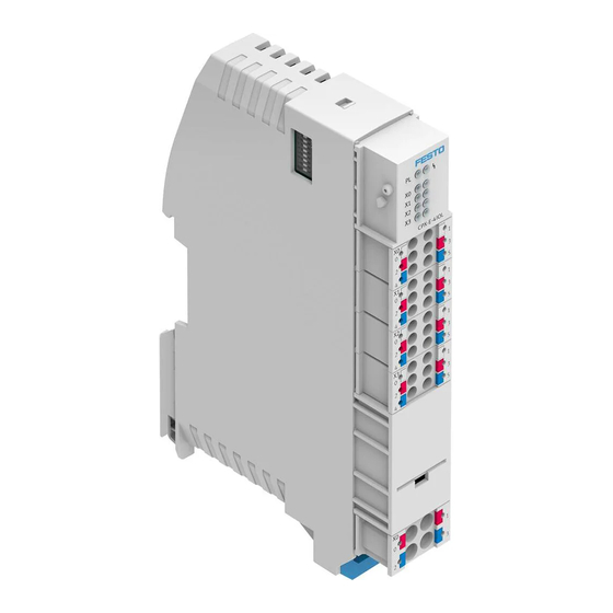
Io-link master module
Hide thumbs
Also See for CPX-E-4IOL Series:
- Manual (24 pages) ,
- Instructions for use (3 pages) ,
- Operating instructions (4 pages)

Subscribe to Our Youtube Channel
Related Manuals for Festo CPX-E-4IOL Series


Summary of Contents for Festo CPX-E-4IOL Series
- Page 1 CPX-E-4IOL-... IO-Link master module Description | Function, Parameterisation 8126631 8126631 2020-01a [8126633]...
- Page 2 Translation of the original instructions ® IO-Link is a registered trademark of its respective trademark holder in certain countries. Festo — CPX-E-4IOL-... — 2020-01a...
-
Page 3: Table Of Contents
Cycle time (Port 1 … 4)....................20 3.2.6 PL supply (Port 1 … 4).....................21 3.2.7 Operating mode (Port 1 ... 4).................. 21 3.2.8 LineState (Port 1 ... 4)..................... 23 3.2.9 Device error code (Port 1 ... 4)................25 Technical Data......................25 Festo — CPX-E-4IOL-... — 2020-01a... -
Page 4: About This Document
This document describes the function and parameterisation of the product stated in the title. Safe use of the product is described in a separate document è 1.1 Further applicable documents. Further applicable documents All available documents for the product è www.festo.com/pk. Documentation Contents... -
Page 5: Product Labelling
The product version can be identified from the product labelling or with the help of appropriate soft- ware from Festo. Appropriate software for determining the product version can be found in the Festo Support Portal è www.festo.com/sp. Information on using the software can be found in the integrated Help function. -
Page 6: Specified Standards
The operating and load voltage supply are implemented separately. LED indicators are available to display the operating status of the module and connected devices. The address space provided by the module to the IO-Link interfaces (ports) is defined by DIL switches. Festo — CPX-E-4IOL-... — 2020-01a... -
Page 7: Product Design
Display components 1 Module error [P] (red) 2 Standard IO mode (SIO) [X0] … [X3] (yellow) 3 IO-Link mode (IOL) [X0] … [X3] (green) 4 Load voltage supply U [PL] (green) Fig. 3 LED indicators Festo — CPX-E-4IOL-... — 2020-01a... -
Page 8: Control Elements
Tab. 6 Connection [X0] ... [X3] Port [XD] Signal +24 V DC load voltage supply U 0 V DC load voltage supply U 1) The ports XD.0 and XD.1 and also XD.2 and XD.3, are interconnected in the terminal strip. Tab. 7 Connection [XD] Festo — CPX-E-4IOL-... — 2020-01a... -
Page 9: Function Example
IO-Link (IO-Link communication takes place at the port) The module described in this document has IO-Link interfaces (ports) of Class B (Type B) that provide an additional load voltage supply. The devices description by IODD (IO Device Description) is not supported. Festo — CPX-E-4IOL-... — 2020-01a... -
Page 10: Diagnostics
IO-Link channel diagnosis Read out the event code Device indicates an event or connection to Tab. 14 Event codes) through the è device interrupted “Device error code” ( Tab. 24)and perform è Flashes the corresponding remedial measures. Festo — CPX-E-4IOL-... — 2020-01a... - Page 11 Load voltage supply U exists Undervoltage of the load voltage supply Check the load voltage supply U on at least one device Flashes Load voltage supply U not present or undervoltage Tab. 11 Load voltage supply [PL] Festo — CPX-E-4IOL-... — 2020-01a...
-
Page 12: Diagnostic And Error Messages
Diagnostic and error messages Malfunctions or errors are sent to the bus module as an error number and can be evaluated by the net- work or suitable Festo software. The prerequisite for sending diagnostic/error messages (if supported by the network) is an existing connection to the host system and a corresponding parameterisation of the module è... - Page 13 Check installation. Port configuration error Check configuration. Invalid switch setting Check DIL switch setting. 1) (only relevant if PL monitoring is active in a device) 2) L+, P24 Tab. 13 Diagnostic/error messages according to error numbers Festo — CPX-E-4IOL-... — 2020-01a...
-
Page 14: Event Codes
0x6000 Device software error 0x6320 Parameter error check data sheet and values – 0x6321 missing parameter check data sheet – 0x6350 Changed parameter check configuration – 0x7700 Wire break at device peripheral check installation – Festo — CPX-E-4IOL-... — 2020-01a... -
Page 15: Parameterisation
5 … PS supply Tab. 19 è – Reserved Settings of Port 1 Cycle time (low) Tab. 20 è Cycle time (high) PL supply + 10 Tab. 21 è Operating mode + 11 Tab. 22 è Festo — CPX-E-4IOL-... — 2020-01a... - Page 16 Status of port 3 LineState + 30 Tab. 23 è Device error code (low) + 31 Tab. 24 è Device error code (high) + 32 Status of port 4 LineState + 33 Tab. 23 è Festo — CPX-E-4IOL-... — 2020-01a...
-
Page 17: Parameter
Selection via parameter F no. 4828 + Deactivate monitoring inactive Activate monitoring Active (default) 1) Function number (è Description of automation system CPX-E); m = module number (counted from left to right, starting from 0) Tab. 16 Festo — CPX-E-4IOL-... — 2020-01a... -
Page 18: Behaviour After Scs
Leave load voltage deac- Leave deactivated tivated Reactivate load voltage reactivate (default) automatically 1) Function number (è Description of automation system CPX-E); m = module number (counted from left to right, starting from 0) Tab. 18 Festo — CPX-E-4IOL-... — 2020-01a... -
Page 19: Ps Supply
F no. 4828 + Deactivate operating inactive voltage Activate operating active (default) voltage 1) Function number (è Description of automation system CPX-E); m = module number (counted from left to right, starting from 0) Tab. 19 Festo — CPX-E-4IOL-... — 2020-01a... -
Page 20: Cycle Time (Port 1
1) Function number (è Description of automation system CPX-E); m = module number (counted from left to right, starting from 0) 2) In case of a setting of 0, the minimum supported cycle time of the IO-Link device is used. Tab. 20 Festo — CPX-E-4IOL-... — 2020-01a... -
Page 21: Supply (Port 1
The setting can be made separately for each IO-Link interface (port). Parameter – Operating mode Setting Comments Selection via parameter F no. 4828 + Operating mode port 1 Inactive Port is not in use (default) + 11 Festo — CPX-E-4IOL-... — 2020-01a... - Page 22 1) Function number (è Description of automation system CPX-E); m = module number (counted from left to right, starting from 0) 2) The parameter setting results in a parameter error (error number 29) and the parameter setting of the port switches to "Inactive". Tab. 22 Festo — CPX-E-4IOL-... — 2020-01a...
-
Page 23: Linestate (Port 1
Scanning IO-Link communication + 27 started, IO-Link device not yet found DeviceLost Communication to IO-Link + 27 device interrupted LineState Port 3 Inactive Port is deactivated + 30 Port is a digital input + 30 Festo — CPX-E-4IOL-... — 2020-01a... - Page 24 2) Function number (è Description of automation system CPX-E); m = module number (counted from left to right, starting from 0) 3) IO-Link communication established 4) IO-Link communication is established; process data are being transferred Tab. 23 Festo — CPX-E-4IOL-... — 2020-01a...
-
Page 25: Device Error Code (Port 1
CPX-E-4IOL CPX-E-4IOL-EX1E General technical data Description of automation system CPX-E Automation system CPX-E 1.1 Further applicable documents è Dimensions [mm] 124.3 18.9 76.6 × × (length width × × height) Product weight Mounting position Vertical/horizontal Festo — CPX-E-4IOL-... — 2020-01a... - Page 26 DIL switches Tab. 5 DIL switch è 1) not including linking element 2) Including linking element 3) for horizontal mounting position 4) dependent on the setting of the DIL switches Tab. 25 General Technical Data Festo — CPX-E-4IOL-... — 2020-01a...
- Page 27 U EL/SEN Mains buffering time [ms] EL/SEN Load voltage supply [V DC] 24 25% Capacitive load U [nF] Undervoltage identification U EL/SEN Trigger level [V DC] Hysteresis [V DC] 1) without connected devices Tab. 26 Power Supply Festo — CPX-E-4IOL-... — 2020-01a...
- Page 28 è switch Short-circuit protection operating voltage supply U EL/SEN Electronic (per module) Thermal (per port) Behaviour after end of overload Can be parameterised Short-circuit protection load voltage supply U Electronic (per module) Thermal (per port) Festo — CPX-E-4IOL-... — 2020-01a...
- Page 29 2) The cycle time used can be permanently set using the “Cycle time” parameter. 3) without feedback protection Tab. 27 IO-Link Ports Ambient conditions UL/CSA Pollution degree Installation site for indoor use only Max. installation height [m] 2000 Tab. 28 Ambient Conditions UL/CSA Festo — CPX-E-4IOL-... — 2020-01a...
- Page 30 Copyright: Festo SE & Co. KG Ruiter Straße 82 73734 Esslingen Germany Phone: +49 711 347-0 Internet: www.festo.com © 2020 all rights reserved to Festo SE & Co. KG...
Need help?
Do you have a question about the CPX-E-4IOL Series and is the answer not in the manual?
Questions and answers