
Related Manuals for Festo CPX-E Series


Summary of Contents for Festo CPX-E Series
- Page 1 System CPX-E Bus module CPX-E-PB Description Protocol PROFIBUS DP Function Parameterisation 8071123 2017-07 [8071125]...
- Page 2 Original instructions CPX-E-PB-E N ® PI PROFIBUS PROFINET is a registered trademark of its respective trademark holder in certain countries. Symbols used: Note Material damage or loss of function Recommendations, tips, references to other documentation Festo – CPX-E-PB-EN – 2017-07 –...
-
Page 3: Table Of Contents
..................Festo – CPX-E-PB-EN – 2017-07 – English... -
Page 4: About This Document
Bus module CPX-E-PB, revision 3 onward Tab. 1.2 The product version can be identified from the product label or with the help of appropriate software from Festo. Appropriate software for identifying the product version can be found in the Festo Support Portal è... -
Page 5: Product Labelling
The product labelling is located on the left-hand side of the module. Scanning the printed Data Matrix Code with an appropriate device calls up the Festo Support Portal, with information appropriate for the product. Alternatively, the Product Key (11-digit alphanumeric code on the product labelling) can be entered in the search field of the Support Portal. -
Page 6: Function
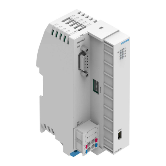
Bus error [BF] (red) 2 System-specific LED indicators: – Operating voltage supply U [PS] EL/SEN (green) – Load voltage supply U [PL] (green) – System fault [SF] (red) – Force mode [M] (yellow) Fig. 2.2 Festo – CPX-E-PB-EN – 2017-07 – English... -
Page 7: Control Elements
1) The ports XD.0 and XD.1 and also XD.2 and XD.3 are interconnected in the terminal strip. Tab. 2.4 Diagnostic interface [DIAG] Via the diagnostic interface [DIAG] (mini-USB), the bus module can be connected to a PC on which parameterisation and diagnostics software is installed. Festo – CPX-E-PB-EN – 2017-07 – English... -
Page 8: Device Description File
(GSD file). This file contains all the information required for parameterising the system CPX-E using controller software (such as Siemens STEP 7). The device description file is available at the Festo Support Portal è www.festo.com/sp. 2.1.6 Control commands The control commands FREEZE, SYNC and CLEAR_DATA are supported by system CPX-E according to PROFIBUS specification IEC 61158. -
Page 9: Address Assignment
Digital output module CPX-E-8DO – A0 … 7 Digital output module CPX-E-8DO – A8 … 15 Analogue input module CPX-E-4AI-U-I I24 … I87 – Analogue output module CPX-E-4AO-U-I – O16 … O79 Tab. 2.5 Festo – CPX-E-PB-EN – 2017-07 – English... -
Page 10: Diagnostics Options
PROFIBUS functionality. Detailed module-related and channel-related error detection by means of control software. PROFIBUS DPV1 Expanded access to the system data of system CPX-E through the network using controller software. Tab. 2.6 Festo – CPX-E-PB-EN – 2017-07 – English... -
Page 11: Led Indicators
The I/O diagnostic interface is displayed in the process image insofar as set by the selection of the catalogue entry “CPX-E-PB DP-Slave [DP-V1]” in the hardware configurator. You can find detailed information about the I/O diagnostic interface in the “Description of system CPX-E” è 1.1 Further applicable documents. Festo – CPX-E-PB-EN – 2017-07 – English... -
Page 12: Diagnosis Via Profibus Dp
Station status 3 Diag.Master_add Address of the master parameterised by system CPX-E. Ident_number – High Byte Manufacturer identifier – High Byte (0F Ident_number – Low Byte Manufacturer identifier – Low Byte (A3 Tab. 2.8 Festo – CPX-E-PB-EN – 2017-07 – English... - Page 13 1) The entry is made gap-free in ascending order according to module numbers and independently of the temporal sequence of the diagnostic messages. If necessary, entries with larger module numbers are moved. 2) 11 diagnostic messages maximum can be processed. Tab. 2.11 Festo – CPX-E-PB-EN – 2017-07 – English...
-
Page 14: Standard Diagnostic Information
Station status 3 Meaning Explanation 0 … 6 Reserved – Diag.Ext_Diag_Overflow 1 = system CPX-E has more diagnostic messages than can be buffered or master contains more diagnostic messages than it can buffer. Tab. 2.14 Festo – CPX-E-PB-EN – 2017-07 – English... -
Page 15: Identifier-Related Diagnosis
11 diagnostic messages maximum can be processed. Module number Settings Byte 7 6 5 4 3 2 1 0 Module number 0 … 63 Bit 6 and Bit 7 are permanently set Tab. 2.17 Festo – CPX-E-PB-EN – 2017-07 – English... - Page 16 Parameterisation error (upper limit value) 9 … 15 Reserved Actuator supply faulty 27 … 29 Reserved Slave has no network connection Channel failed 1) For bus module CPX-E-PB, the relevant error types are bolded. Tab. 2.20 Festo – CPX-E-PB-EN – 2017-07 – English...
-
Page 17: Parameterisation
Parameterisation Parameterisation The behaviour of the system CPX-E can be parameterised with the aid of suitable software from Festo or using a higher-order controller. Here, a distinction is made between the following variants: – System parameters – Module parameters (module-specific and channel-specific) –... - Page 18 Module forcen: Outputs – Module forcen: Inputs – Module forcen: Inputs – 1) r = read access; w = write access 2) Siemens S7: “S7-compatible” parameter setting 3) m = Module number Tab. 3.4 Festo – CPX-E-PB-EN – 2017-07 – English...
-
Page 19: Examples For Access To Data Records Through Dpv1
First, the command box is assigned as follows è Tab. 3.6. Command box assignment Byte Table of contents Slot number Index number Offset – Example – Tab. 3.6 After that, the diagnostic memory entry 0 must be read with Read Box. Festo – CPX-E-PB-EN – 2017-07 – English... -
Page 20: Operation With The General Dp Master
The transmission times depend on the cycle time of the PLC and update time of the network. Independently of structure, the delay times within system CPX-E amount to less than 1 ms. The calculation of the overall transmission time can be found in the controller user documentation. Festo – CPX-E-PB-EN – 2017-07 – English... -
Page 21: Bus Start
WD_Fact_1 of system CPX-E with these two octets. (range of values respectively 1 … 255) WD_Fact_2 TWD [s] = 10 ms x WD_Fact_1 x WD_Fact_2 1) Octet 1 2) Octet 2 Tab. 3.10 Festo – CPX-E-PB-EN – 2017-07 – English... -
Page 22: Check Configuration Data - Chk_Cfg
The behaviour of system CPX-E in case of a fault, e.g., in case of a network failure, depends on the parameterised behaviour of the master interface and the fail-safe setting. Information on this topic can be found in “Description of system CPX-E” è 1.1 Further applicable documents. Festo – CPX-E-PB-EN – 2017-07 – English... -
Page 23: Transfer Input And Output Data - Data_Exchange
… … (v+7).0 (v+7).1 … … (v+7).7 1) Output byte 3) Input byte 2) Address offset of master module: x, y, z 4) Address offset of master module: t, u, v Tab. 3.15 Festo – CPX-E-PB-EN – 2017-07 – English... -
Page 24: A Technical Data
24 ± 25 % EL/SEN Intrinsic current consumption at nominal operating [mA] voltage 24 V from U EL/SEN Reverse polarity protection 24 V U against EL/SEN 0 V U EL/SEN Mains buffering time [ms] Tab. A.2 Festo – CPX-E-PB-EN – 2017-07 – English... - Page 25 Capacitance per unit length [pF/m] š 110 Loop resistance [Ω/km] , 0.64 Wire diameter [mm] , 0.34 Wire cross section [mm²] 1) Dependent on transmission rate 2) According to IEC 61158 (Type A) Tab. A.3 Festo – CPX-E-PB-EN – 2017-07 – English...
-
Page 26: B Terminology
Collective term for modules that can be integrated in a system CPX-E. Programmable logic controller Status bits Internal status information (common diagnostic messages) of the system CPX-E, provided as input signals via the network. System CPX-E Complete system consisting of modules CPX-E. Tab. B.1 Festo – CPX-E-PB-EN – 2017-07 – English... -
Page 27: Index
– I/O diagnostics interface, 11 Terminology, 26 – LED indicators, 11 Transfer data, 23 – Status bits, 11 Transmission rate, 20 – Via PROFIBUS DP, 12 Transmission times, 20 FREEZE, 8 Further applicable documents, 4 Festo – CPX-E-PB-EN – 2017-07 – English... - Page 28 Copyright: Festo SE & Co. KG Ruiter Straße 82 73734 Esslingen Germany Phone: +49 711 347-0 Fax: +49 711 347-2144 e-mail: Reproduction, distribution or sale of this document or communication of service_international@festo.com its contents to others without express authorization is prohibited. Offend...
Need help?
Do you have a question about the CPX-E Series and is the answer not in the manual?
Questions and answers