Festo MS6-SV D-10V24 Series Operating Instructions Manual
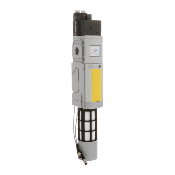
Soft-start/quick exhaust valve
Hide thumbs
Also See for MS6-SV D-10V24 Series:
- Operating instructions manual (68 pages) ,
- Instructions manual (38 pages) ,
- Assembly installation safety instructions (26 pages)

Related Manuals for Festo MS6-SV D-10V24 Series


Summary of Contents for Festo MS6-SV D-10V24 Series
- Page 1 MS6-SV-...-D-10V24 Soft-start/quick exhaust valve Operating instruc- tions 8164008 2022-06c [8164010]...
- Page 2 Translation of the original instructions...
-
Page 3: Table Of Contents
12.6 Exhaust time............. 26 Festo — MS6-SV-...-D-10V24 — 2022-06c... -
Page 4: About This Document
The document contains additional information for use of the product in safety-related systems (safety handbook in accordance with IEC 61508). Applicable documents All available documents for the product è www.festo.com/sp. Target group The document is targeted towards individuals who mount and operate the product. It is additionally targeted towards individuals who are entrusted with the planning and application of the product in a safety-oriented system. -
Page 5: Foreseeable Misuse
The qualified personnel have skills and experience in dealing with electropneumatic (open-loop) control technology. Additional information – Contact the regional Festo contact if you have technical problems è www.festo.com. – Accessories and spare parts è www.festo.com/catalogue. Festo — MS6-SV-...-D-10V24 — 2022-06c... -
Page 6: Product Overview
Flow control screw for soft-start function Proximity switch S1 Function The product changes from the normal position to the switching position when both coils are energised simultaneously. The normal position is achieved by switching off both coils. Festo — MS6-SV-...-D-10V24 — 2022-06c... - Page 7 In the normal position (completely exhausted product), the pilot valves V1 and V2 are not actuated. If both pilot valves are actuated, the product switches first to the switching position 1 and then, when the switch-through pressure is reached, automatically into switching position 2 è Fig. 2. Festo — MS6-SV-...-D-10V24 — 2022-06c...
- Page 8 Full flow rate from port 1 to 2, passage from port 2 to 3 closed. Tab. 4: Switching logic Switching characteristics Switching behaviour of the product's internal valves. The normally exhausted position is sensed by the proximity switch. Switching logic è Tab. 4 Switching logic. Festo — MS6-SV-...-D-10V24 — 2022-06c...
- Page 9 Switch-through pressure There is a flow control screw in the cover of the product. The flow control screw can be used to generate a gradual pressure build-up of output pressure p2 è 12.5 Filling flow. Festo — MS6-SV-...-D-10V24 — 2022-06c...
- Page 10 S1 = 1 à 0; S2 = 1 à 0 S1 and S2. Optional, when using a third proximity switch S3 Record edge change at proximity switch S3 = 1 à 0 Corresponding reaction times è Fig. 2. Festo — MS6-SV-...-D-10V24 — 2022-06c...
- Page 11 S2 = 1 à 0 Switch off voltage to pilot valve V2. V2 = 0 Record edge change at proximity switch S2 = 0 à 1 Corresponding reaction times è Fig. 2. Tab. 6: Recommendation for actuation and diagnostics Festo — MS6-SV-...-D-10V24 — 2022-06c...
-
Page 12: Information On Functional Safety
To achieve the desired performance level, the applicable measures against CCF must be implemented in accordance with the specifications of EN ISO 13849-2. value The PFH value depends on the model of the product and the annual actuation rate (n Festo — MS6-SV-...-D-10V24 — 2022-06c... - Page 13 Product overview value MS6-SV-…-D Fig. 4: PFHd value MS6-SV-…-D 1 PFHd [10 -7] 2 Actuation rate (nop) [10 4/a] value MS6-SV-…-D-S3 Fig. 5: PFHd value MS6-SV-…-D-S3 1 PFHd [10 -8] 2 Actuation rate (nop) [10 4/a] Festo — MS6-SV-...-D-10V24 — 2022-06c...
-
Page 14: Assembly
The free space ensures the exhaust can escape. Fig. 6: Mounting Preparation • Observe the flow direction from port 1 to port 2. Numbers 1 and 2 on the housing è Fig. 7 are provided for orientation. Festo — MS6-SV-...-D-10V24 — 2022-06c... -
Page 15: Assembly With Ms-Series Service Unit Components
If devices that impair the exhaust are placed behind the pneumatic connection 2 of the soft start/quick exhaust valve, this can result in loss of the safety function. • Only place devices that do not impair the exhaust downstream of pneumatic connection 2. Festo — MS6-SV-...-D-10V24 — 2022-06c... -
Page 16: Installation
1. Note the screw-in depth of the connector thread: 10 mm. 2. Make sure that the compressed air lines are connected correctly. 3. Screw the fittings into the pneumatic ports using a suitable sealing material. Festo — MS6-SV-...-D-10V24 — 2022-06c... -
Page 17: Electrical Installation
Port 3 Exhausting a system using the product results in high noise levels. • Recommendation: use silencer è www.festo.com/catalogue. 1. Screw the silencer into pneumatic port 3. 2. Make sure that the exhaust is unrestricted. Neither the silencer nor port 3 may be blocked. -
Page 18: Commissioning
Perform a forced switch-off at least once a month if the process-related switching frequency is lower. Maintenance Maintenance work A dirty silencer can extend the time needed for exhausting the system and thus restrict the safety function. • Check the silencer regularly and replace if necessary. Festo — MS6-SV-...-D-10V24 — 2022-06c... -
Page 19: Cleaning
– Check power supply – Check installation of the signal lines – Start device è 7 Commissioning. – Implement possible remedies è Tab. 8 Fault clearance. – If the fault occurs again: contact Festo service è www.festo.com. Malfunction Possible cause Remedy –... -
Page 20: Technical Data
Note on forced checking pro- Switching frequency min. 1/month cedure 1) Depending on the average number of actuations per year (nop). Tab. 9: Safety data MS6-SV-...-D Certificates, declaration of conformity è www.festo.com/sp Tab. 10: Product conformity Festo — MS6-SV-...-D-10V24 — 2022-06c... -
Page 21: Technical Data, Mechanical
27 … 58 27 … 60 – – ±0.15 ±0.35 58 … 160 60 … 160 – – 160 … 200 160 … 200 – – Shock load Acceleration [m/s Duration [ms] Shocks per direction ±150 ±300 Festo — MS6-SV-...-D-10V24 — 2022-06c... -
Page 22: Technical Data, Pneumatic
£ 0.04; at p1 = 1 MPa and flow control valve fully open Residual pressure in the [MPa] event of error £ 0.4; at p1 = 10 bar and flow control valve fully open [bar] Festo — MS6-SV-...-D-10V24 — 2022-06c... - Page 23 Standard flow rate 2 } 3 in [l/min] the event of a critical fault Switch-through point Approx. 50% of p1 Filling flow Adjustable by flow control valve ³ 1 minimum pause time after exhaust Tab. 13: Technical data, pneumatic Festo — MS6-SV-...-D-10V24 — 2022-06c...
-
Page 24: Technical Data, Electrical
1.8 (at 24 V DC) coil Proximity switch SMT-8M-A-PS-24V-E Nominal operating voltage ±10 permissible voltage fluctua- tions Switching element function N/O contact Measurement principle Magneto-resistive Switching status display Switching output Tab. 14: Technical data, electrical Festo — MS6-SV-...-D-10V24 — 2022-06c... -
Page 25: Filling Flow
= 1 MPa (10 bar; 145 psi) p1 = 0.8 MPa (8 bar; 116 psi) p1 = 0.6 MPa (6 bar; 87 psi) p1 = 0.4 MPa (4 bar; 58 psi) Fig. 10: Flow diagram Festo — MS6-SV-...-D-10V24 — 2022-06c... -
Page 26: Exhaust Time
(0.36) (0.52) 0.45 0.55 (0.4) (0.6) (0.8) (1.1) (1.2) (1.9) 0.85 (0.8) (1.25) (1.5) (2.2) (2.4) (3.9) (1.7) (2.8) (3.4) (5.3) (5.1) (8.1) 11.0 12.8 (4.8) (8.2) (9.8) (15.4) (16.2) (29.0) Tab. 15: Exhaust time Festo — MS6-SV-...-D-10V24 — 2022-06c... - Page 28 Copyright: Festo SE & Co. KG 73734 Esslingen Ruiter Straße 82 Deutschland Phone: +49 711 347-0 Internet: © 2022 all rights reserved to Festo SE & Co. KG www.festo.com...
Need help?
Do you have a question about the MS6-SV D-10V24 Series and is the answer not in the manual?
Questions and answers