Table of Contents
Advertisement
This manual serves the following
ComNet Model Numbers:
CNGE2+2SMS
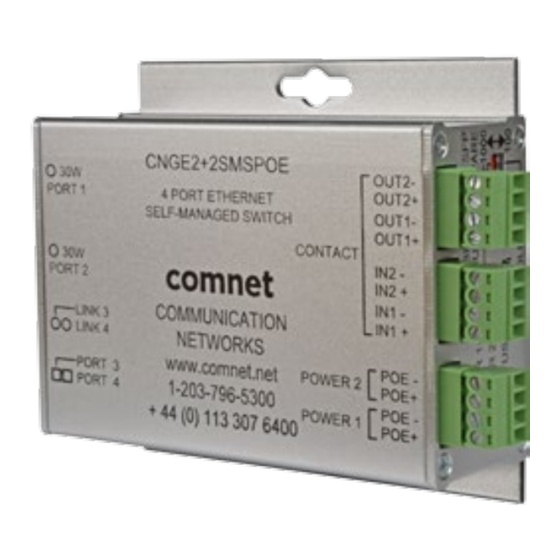
CNGE2+2SMSPOE
CNGE2+2SMSPOEHO
INSTALLATION AND OPERATION MANUAL
CNGE2+2SMS[POE][HO]
10/100/1000 MBPS INTELLIGENT REDUNDANT RING
GIGABIT SWITCH WITH OPTIONAL POE+
The ComNet CNGE2+2SMS[POE][HO] is a four port intelligent switch with light
management functionality. It provides two 10/100/1000Base-T(X) copper ports and
two 100/1000Base-FX SFP ports. The CNGE2+2SMS[POE][HO] provides exclusive
functionality for easy field deployment including DIP switch based operation of
RSTP for creating redundant network topologies as well as preventing network video
flooding of multicast traffic with IGMP snooping. Ports 1 and 2 can optionally supply
up to thirty (30) watts of power per port based on the IEEE 802.3at standard. An
optional High Output (HO) version is also available that can supply up to sixty (60)
watts of PoE from ports 1 and 2. This product is fully compatible with the ComNet
exclusive CopperLine® SFP modules for operation over extended distance UTP or Coax
cable. The ComNet exclusive Port Guardian feature provides additional cyber security
protection by enabling physical port lockout in the event that an existing cable is
disconnected and prevents a potential network incursion using common spoofing
techniques. The intrusion event is reported back to the operator using SNMP.
Advertisement
Table of Contents

Related Manuals for Comnet CNGE2+2SMS


Summary of Contents for Comnet CNGE2+2SMS
- Page 1 High Output (HO) version is also available that can supply up to sixty (60) watts of PoE from ports 1 and 2. This product is fully compatible with the ComNet exclusive CopperLine® SFP modules for operation over extended distance UTP or Coax cable.
-
Page 2: Table Of Contents
Switch Port Configuration Port Statistics RSTP System Configuration RSTP Port Configuration LLDP Active Ping Check Configuration Non PoE Model CNGE2+2SMS PoE Model CNGE2+2SMSPOE and CNGE2+2SMSPOEHO 32 Authentication Username and Password Configuration Upgrade Firmware TECH SUPPORT: 1.888.678.9427 INS_CNGE2+2SMS_REV– 02/19/13 PAGE 2... - Page 3 INSTALLATION AND OPERATION MANUAL CNGE2+2SMS[POE][HO] Factory Defaults System Reset Network Interface Configuration SNMP SNMP – Config CNGE2+2SMSPOE[HO] PoE-PSE-Status Information CNGE2+2SMSPOE[HO] PoE Contact Information Port Guardian Port Guardian – CLI Reset Static Multicast MAC Routing Per Port Static MAC Lock Configuration...
-
Page 4: Regulatory Compliance Statement
ComNet warrants that all ComNet products are free from defects in material and workmanship for a specified warranty period from the invoice date for the life of the installation. ComNet will repair or replace products found by ComNet to be defective within this warranty period, with shipment expenses apportioned by ComNet and the distributor. -
Page 5: Overview
Overview Introduction The CNGE2+2SMS is a light managed, hardened Ethernet switch that contains many features. The switch will work under a wide variety of temperature, dirty and humid conditions. It can be managed through WEB, USB Console or other third-party SNMP software. With the easy to use and intuitive web and CLI interfaces, the switch can be easily monitored by a utility called eVision, which is part of the ComNet eConsole software suite. -
Page 6: Hardware Features
INSTALLATION AND OPERATION MANUAL CNGE2+2SMS[POE][HO] Hardware Features » 7 × DIP Switches for quick feature selection » 2 × Redundant DC power inputs » Operating Temperature: -40 – 75ºC » Storage Temperature: -40 – 85ºC » Operating Humidity: 5% – 95%, non-condensing »... -
Page 7: Hardware Overview
INSTALLATION AND OPERATION MANUAL CNGE2+2SMS[POE][HO] Hardware Overview Side Panels The following table describes the ports that are on the sides of the CNGE2+2SMS. Port Description 10/100/1000Base-T(X) 2 × 10/100/1000Base-T(X) RJ-45 fast Ethernet ports support RJ-45 Ethernet ports auto-negotiation. Default Settings:... - Page 8 INSTALLATION AND OPERATION MANUAL CNGE2+2SMS[POE][HO] CNGE2+2SMS Configuration DIP switches Console Mini USB LED for PWR1 LED for PWR2 LED for STATUS Power Connections RJ-45 Ports Link/Activity LEDs for SFP Port 3 Link/Activity LEDs for SFP Port 4 SFP Ports TECH SUPPORT: 1.888.678.9427...
- Page 9 INSTALLATION AND OPERATION MANUAL CNGE2+2SMS[POE][HO] CNGE2+2SMSPOE CNGE2+2SMSPOEHO Power connections Contact IN terminal block Contact OUT terminal block Configuration DIP switches Console Mini USB LED for Power 1 LED for Power 2 LED for Status RJ-45 Ports PoE Status LEDs for RJ-45 Port 1...
-
Page 10: Indicating Leds
INSTALLATION AND OPERATION MANUAL CNGE2+2SMS[POE][HO] Indicating LEDs Color Status Description PWR1 Green DC Power Input 1 Good No power detected PWR2 Green DC Power Input 2 Good No power detected STATUS Green Initialization passed Failed 10/100/1000Base-T(X) Ethernet ports LNK/ACT Green... -
Page 11: Cables
Cables Ethernet Cables The CNGE2+2SMS switches have standard Ethernet ports. According to the link type, the switches use CAT 3, 4, 5, & 5e UTP cables to connect to any other network device (PCs, servers, switches, routers, or hubs). Please refer to the following table for cable specifications. - Page 12 BI_DC- BI_DB- BI_DD+ BI_DD- The CNGE2+2SMS switches support auto MDI/MDI-X operation. You can use a straight-through cable to connect PC to switch. The following table below shows the 10/100BASE-T(X) MDI and MDI-X port pin-outs: 10/100 Base-T MDI/MDI-X pin assignments Pin Number...
-
Page 13: Sfp
INSTALLATION AND OPERATION MANUAL CNGE2+2SMS[POE][HO] The Switch has fiber optic ports that utilize SFP connectors. ComNet offers a wide selection of SFP modules that offer different fiber type, connector type and distances. Please remember that the TX port of Switch A should be connected to the RX port of Switch B. -
Page 14: Dip Switches
CNGE2+2SMS[POE][HO] DIP Switches The CNGE2+2SMS’s dip switches configure switch features. The DIP Switches are numbered from left to right when viewing the side of the Switch with the backplate on the bottom and the power connections on the left. If “Web Management Enable” is selected in the management software under System Settings, the DIP switch settings will be overridden by any settings made in the browser interface. - Page 15 INSTALLATION AND OPERATION MANUAL CNGE2+2SMS[POE][HO] SMS MUX Disabled (DIP Switch 2 in OFF Position) SMS MUX Enabled (DIP Switch 2 in On Position) TECH SUPPORT: 1.888.678.9427 INS_CNGE2+2SMS_REV– 02/19/13 PAGE 15...
- Page 16 INSTALLATION AND OPERATION MANUAL CNGE2+2SMS[POE][HO] Redundant SFP (RSFP) Enabled (DIP Switch 4 in On Position) Note: There is no port isolation between Ports 1 & 2 as shown. Ports 1 & 2 are free to send traffic between each other as per a normal switch.
- Page 17 INSTALLATION AND OPERATION MANUAL CNGE2+2SMS[POE][HO] Redundant SFP (RSFP) Enabled (3rd Party Switch) (DIP Switch 4 in On Position) Note: Disabling MAC Address Learning on the 3rd party switch (if supported) can sometimes allow for faster port switchover times. There is no port isolation between Ports 1 & 2 as shown. Ports 1 & 2 are free to send traffic between each other as per a normal switch.
- Page 18 INSTALLATION AND OPERATION MANUAL CNGE2+2SMS[POE][HO] Redundant SFP (RSFP) Enabled + SMS MUX Enabled (3rd Party Switch) (DIP Switch 2 & 4 ON) Note: Disabling MAC Address Learning on the 3rd party switch (if supported) can sometimes allow for faster port switchover times.
- Page 19 RSTP Enabled (Single Ring) (DIP Switch 1 ON) See Note Below Attention: ComNet recommends maximum number of units per ring is limited to 20 devices. Numbers higher than this may cause undesired performance and are not supported by ComNet. Note: The unit at the control room location should have DIP switch 3 ON (ROOT BR). This will force the ring to break at the half way point and ensure most effective load sharing on the network.
- Page 20 INSTALLATION AND OPERATION MANUAL CNGE2+2SMS[POE][HO] RSTP Enabled (Multiple Rings) (DIP Switch 1 ON) Attention: ComNet recommends maximum number of units per ring is limited to 20 devices. Numbers higher than this may cause undesired performance and are not supported by ComNet.
- Page 21 CNGE2+2SMS[POE][HO] IGMP & RSTP Enabled (DIP Switch 1 & 5 ON) Important Note: The CNGE2+2SMS supports IGMP snooping only. When using the IGMP function a managed switch must be implemented within the network that is configured as the IGMP Querier as shown.
-
Page 22: Web Management
INSTALLATION AND OPERATION MANUAL CNGE2+2SMS[POE][HO] WEB Management Attention: While installing and upgrading firmware, please remove physical loop connection first. DO NOT power off equipment while the firmware is upgrading! Configuration by Web Browser This section provides instruction on configuration through the Web browser. - Page 23 INSTALLATION AND OPERATION MANUAL CNGE2+2SMS[POE][HO] System Login 1. Launch your Web Browser. 2. Type http:// and the IP address of the switch. Press Enter. 3. The login screen appears. 4. Enter username and password. The default username and password is admin.
- Page 24 INSTALLATION AND OPERATION MANUAL CNGE2+2SMS[POE][HO] Main Interface Main interface TECH SUPPORT: 1.888.678.9427 INS_CNGE2+2SMS_REV– 02/19/13 PAGE 24...
-
Page 25: System Information
INSTALLATION AND OPERATION MANUAL CNGE2+2SMS[POE][HO] System Information The switch system information is provided here. System Information interface Label Description Switch Settings Summary table of external switch settings Web Management Enable Override the side panel switches setting to use the webpage settings instead. -
Page 26: Switch Port Configuration
INSTALLATION AND OPERATION MANUAL CNGE2+2SMS[POE][HO] Switch Port Configuration Unless you have reason to change this setting, it is recommended to leave the negotiation set to auto. The link segment requires forcing the settings. Both ends of the link need to have the same selection. -
Page 27: Port Statistics
INSTALLATION AND OPERATION MANUAL CNGE2+2SMS[POE][HO] Port Statistics Use the refresh button to update the port statistics. Port Statistics interface TECH SUPPORT: 1.888.678.9427 INS_CNGE2+2SMS_REV– 02/19/13 PAGE 27... -
Page 28: Rstp System Configuration
INSTALLATION AND OPERATION MANUAL CNGE2+2SMS[POE][HO] RSTP System Configuration The Rapid Spanning Tree Protocol (RSTP) is an evolution of the Spanning Tree Protocol. It provides faster spanning tree convergence after a topology change. The system also supports STP and the system will auto detect the connected device that is running STP or RSTP protocol. -
Page 29: Rstp Port Configuration
INSTALLATION AND OPERATION MANUAL CNGE2+2SMS[POE][HO] RSTP Port Configuration RSTP Port configuration interface Label Description Port Priority Configure port priority, must be a multiple of 16. Port Admin Configure port Admin or Auto Edge status. Port Status Summary table of RSTP port status Important Note: A system reset must be performed after making changes to the RSTP settings. -
Page 30: Lldp
INSTALLATION AND OPERATION MANUAL CNGE2+2SMS[POE][HO] LLDP LLDP (Link Layer Discovery Protocol) function allows the switch to advertise its information to other nodes on the network and store the information it discovers. LLDP is enabled by default with the interval set to 10 seconds. -
Page 31: Active Ping Check Configuration
CNGE2+2SMS[POE][HO] Active Ping Check Configuration Non PoE Model CNGE2+2SMS The active ping check function allows the switch to check that a configured IP address is alive on each of the RJ45 ports. If the specified IP address becomes unreachable then the switch will perform the action selected in the Failure Action menu. -
Page 32: Poe Model Cnge2+2Smspoe And Cnge2+2Smspoeho
INSTALLATION AND OPERATION MANUAL CNGE2+2SMS[POE][HO] PoE Model CNGE2+2SMSPOE and CNGE2+2SMSPOEHO Label Description Enable Select to enable the active ping check function Interval Active ping check interval in seconds Remote IP Configure IP addresses of remote device to ping Failure action... -
Page 33: Authentication Username And Password Configuration
INSTALLATION AND OPERATION MANUAL CNGE2+2SMS[POE][HO] Authentication Username and Password Configuration The username and password entered here are also used in the CLI. Authentication Username and Password configuration interface TECH SUPPORT: 1.888.678.9427 INS_CNGE2+2SMS_REV– 02/19/13 PAGE 33... -
Page 34: Upgrade Firmware
INSTALLATION AND OPERATION MANUAL CNGE2+2SMS[POE][HO] Upgrade Firmware Upgrade Firmware allows you to update the firmware of the switch. Before updating, have your Windows firmware update application ready and the firmware image is available. RSTP is not available during the firmware update process so please, observe the network topology before upgrading. -
Page 35: Factory Defaults
INSTALLATION AND OPERATION MANUAL CNGE2+2SMS[POE][HO] Factory Defaults Factory Defaults Reset interface This function restores the system configuration back to the factory default values. All parameters will revert back to the original factory default values except the network configuration settings. TECH SUPPORT: 1.888.678.9427... -
Page 36: System Reset
INSTALLATION AND OPERATION MANUAL CNGE2+2SMS[POE][HO] System Reset System Reset interface This feature will perform a system reset. Some system configuration changes require a system reset to take effect: -RSTP changes -File System updates -Network configuration changes - IGMP changes - Static Mack Lock changes... -
Page 37: Network Interface Configuration
INSTALLATION AND OPERATION MANUAL CNGE2+2SMS[POE][HO] Network Interface Configuration Interface Configuration interface Label Description Host Name Assign a name to the device (this is used for CLI and SNMP functions) Enable DHCP To enable or disable the DHCP client function. When DHCP client function is enabled, the switch will be assigned the IP address from the network DHCP server. -
Page 38: Snmp
INSTALLATION AND OPERATION MANUAL CNGE2+2SMS[POE][HO] SNMP Simple Network Management Protocol (SNMP) is the protocol developed to manage nodes (servers, workstations, routers, switches and hubs etc.) on an IP network. SNMP enables network administrators to manage network performance, find and solve network problems, and plan for network growth. -
Page 39: Cnge2+2Smspoe[Ho] Poe-Pse-Status Information
INSTALLATION AND OPERATION MANUAL CNGE2+2SMS[POE][HO] CNGE2+2SMSPOE[HO] PoE-PSE-Status Information Label Description Port Power Displays the amount of power being used on the port in watts Port Power DN Turns off PoE power to the associated port Port Power UP Turns on PoE power to the associated port... -
Page 40: Cnge2+2Smspoe[Ho] Poe Contact Information
INSTALLATION AND OPERATION MANUAL CNGE2+2SMS[POE][HO] CNGE2+2SMSPOE[HO] PoE Contact Information Label Description Output Contact The faults that trigger the output contacts are fully configurable by selecting the source(s) to monitor Contact Override The contacts may also be forced to an opened or closed state, the state... -
Page 41: Port Guardian
INSTALLATION AND OPERATION MANUAL CNGE2+2SMS[POE][HO] Port Guardian The Port Guardian feature provides a high security managed port lock out mode and when enabled will power down the port as soon as a link loss status is detected when a cable is disconnected. This provides high security against network attack by an intruder who accesses the edge device and disconnects it to then try and connect their own intrusion device (laptop, network sniffer etc.). -
Page 42: Port Guardian - Cli Reset
INSTALLATION AND OPERATION MANUAL CNGE2+2SMS[POE][HO] Port Guardian – CLI Reset The Port Guardian feature can be cleared from the USB serial port connection on the unit through the CLI and also the port status can be displayed to show any ports that are in lock out state. -
Page 43: Static Multicast Mac Routing Per Port
INSTALLATION AND OPERATION MANUAL CNGE2+2SMS[POE][HO] Static Multicast MAC Routing Per Port Static Multicast MAC Routing interface Label Description Enable Enable static multicast MAC routing MAC Addr. Destination Multicast MAC address of the stream Port Number Ports to be included in the multicast route Apply Select Apply to activate the configurations. -
Page 44: Static Mac Lock Configuration
INSTALLATION AND OPERATION MANUAL CNGE2+2SMS[POE][HO] Static MAC Lock Configuration Static MAC Lock Configuration interface Label Description Enable Enable static MAC locking MAC Addr. MAC address of the device that is allowed to forward and receive traffic. Packets will be dropped for MAC addresses not listed in the table... -
Page 45: Igmpv2 Snooping
INSTALLATION AND OPERATION MANUAL CNGE2+2SMS[POE][HO] IGMPv2 Snooping IGMPv2 Multicast Routing interface TECH SUPPORT: 1.888.678.9427 INS_CNGE2+2SMS_REV– 02/19/13 PAGE 45... - Page 46 INSTALLATION AND OPERATION MANUAL CNGE2+2SMS[POE][HO] Label Description Enable Enable IGMP Snooping Group timer Must be set above the general query interval Port Timer Expected wait interval of membership reports for a specific group Unregistered Flooding Allow unregistered multicast traffic to propagate across ports...
-
Page 47: Jumbo Frame Support
INSTALLATION AND OPERATION MANUAL CNGE2+2SMS[POE][HO] Jumbo Frame support Jumbo Frame Port Configuration interface Label Description MTU size the drop down box allows for maximum frame size, the default is the maximum frame size 10,240. Not enabled defaults the maximum frame size to 1522 MTU. -
Page 48: Command Line Interface Management
Follow the steps below to access the console via USB mini B cable. Step 1. Connect the USB cable between the PC and the CNGE2+2SMS. If the device driver is not found, the product CD includes the windows .inf driver. - Page 49 INSTALLATION AND OPERATION MANUAL CNGE2+2SMS[POE][HO] Step 3. Select the COM port number Step 4. The COM port properties setting, 115200 for Bits per second, 8 for Data bits, None for Parity, 1 for Stop bits and none for Flow control.
- Page 50 INSTALLATION AND OPERATION MANUAL CNGE2+2SMS[POE][HO] Enter “?” or “help” to list the commands More detailed help for each command is available using help in front of the command name. Issuing a “netinfo” command will display the ip address of the switch...
-
Page 51: Firmware Upgrade Procedure
INSTALLATION AND OPERATION MANUAL CNGE2+2SMS[POE][HO] Firmware Upgrade Procedure Push Bootloader Image Uploader interface The steps for upgrading the unit with the push boot loader are as follows; Bring up the web server and open the FileSystem Upload page click the Enable Image upload check box and hit apply. -
Page 52: Technical Specifications
INSTALLATION AND OPERATION MANUAL CNGE2+2SMS[POE][HO] Technical Specifications Technology Ethernet Standards IEEE 802.3 for 10BASE-T IEEE 802.3u for 100BASE-TX and 100BASE-FX IEEE 802.3z for 1000BASE-X IEEE 802.3ab for 1000BASE-T IEEE 802.1w for RSTP (Rapid Spanning Tree Protocol) IEEE 802.1AB for LLDP (Link Layer Discovery Protocol) IEEE 802.3at for Power Sourcing Equipment (PSE) and PoE (≤... - Page 53 INSTALLATION AND OPERATION MANUAL CNGE2+2SMS[POE][HO] Mechanical Dimension 4.1 × 3.7 × 1.46 in (10.4 × 9.4 × 3.7 cm) Casing Aluminum Regulatory Approvals EN50130-4:2011 EN55024:2010 EN55022:2010 EN 55022:2010 Radiated Emissions EN 55022:2010 Conducted Emissions EN 61000-3-2-2006+A2:2009 Harmonic Current Emissions EN 61000-3-3:2013 Voltage Fluctuations...
- Page 54 INSTALLATION AND OPERATION MANUAL CNGE2+2SMS[POE][HO] TECH SUPPORT: 1.888.678.9427 INS_CNGE2+2SMS_REV– 02/19/13 PAGE 54...
- Page 55 8 TURNBERRY PARK ROAD | GILDERSOME | MORLEY | LEEDS, UK LS27 7LE T: +44 (0)113 307 6400 | F: +44 (0)113 253 7462 | INFO-EUROPE@COMNET.NET © 2017 Communications Networks Corporation. All Rights Reserved. “ComNet” and the “ComNet Logo” are registered trademarks of Communication Networks, LLC.
Need help?
Do you have a question about the CNGE2+2SMS and is the answer not in the manual?
Questions and answers