Table of Contents
Advertisement
Quick Links
INSTALLATION AND OPERATION MANUAL
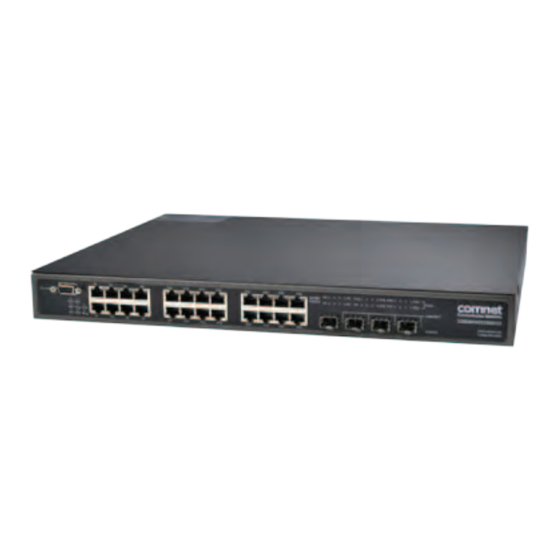
CNGE28FX4TX24MSPOE+
(24) 10/100/1000 BASE-TX + (4) 1000BASE-FX
wiTh PowEr ovEr EThErnET (PoE)
v1.4 Sept 2012
The ComNet
CNGE28FX4TX24MSPOE+ Managed Redundant Ring Ethernet Switch
™
provides robust transmission of (24) 10/100/1000BASE-T(X) ports and (4) 1000BASE-
FX ports of Ethernet data. Fully compliant with IEEE 802.3at, up to 720 watts of PoE or
PoE+ power is available for distribution across all 24 Base-TX ports. The four 1000BASE-
FX ports may be used with multimode or single-mode optical fiber when used with
ComNet SFPs. The exclusive C-Ring protects mission-critical applications from network
interruptions or temporary malfunctions with its fast recovery technology. eConsole,
a powerful, easy-to-use Windows-based utility, allows the CNGE28FX4TX24MSPOE+
to be centrally managed. Diverse media selection provides for easy implementation
of point-to-point, linear add-drop, drop-and-repeat, star, or true self-healing ring and
mesh network system architectures. The electrical ports support the 10/100/1000Mbps
Ethernet IEEE802.3 protocol, and auto-negotiating and auto-MDI/MDIX features
are included for simplicity and ease of installation. These network-managed layer 2
switches are optically (1000BASE-FX) and electrically compatible with any IEEE802.3
compliant Ethernet device. Unlike most Ethernet switches, the environmentally
hardened CNGE28FX4TX24MSPOE+ is designed for direct deployment in difficult
out-of-plant or roadside operating environments. Featuring a low-profile 1-RU high
rack-mountable package, these units may be mounted within any standard 19-inch
rack cabinet, and the high-capacity power supply for operation of the switch and PoE
PSE (Power Sourcing Equipment) is completely self-contained.
Advertisement
Table of Contents

Related Manuals for Comnet CNGE28FX4TX24MSPOE+


Summary of Contents for Comnet CNGE28FX4TX24MSPOE+
- Page 1 PoE+ power is available for distribution across all 24 Base-TX ports. The four 1000BASE- FX ports may be used with multimode or single-mode optical fiber when used with ComNet SFPs. The exclusive C-Ring protects mission-critical applications from network interruptions or temporary malfunctions with its fast recovery technology. eConsole, a powerful, easy-to-use Windows-based utility, allows the CNGE28FX4TX24MSPOE+ to be centrally managed.
-
Page 2: Table Of Contents
INSTALLATION AND OPERATION MANUAL CNGE28FX4TX24MSPOE+ Contents Regulatory Compliance Statement Warranty Disclaimer Safety Indications Overview Introduction Software Features Hardware Features Hardware Overview Front Panel Rear Panel Rack mount kit assembly Front Panel LEDs Cables Ethernet Cables 100BASE-TX/10BASE-T Pin Assignments Console Cable WEB Management Configuration by Web Browser About Web-based Management... -
Page 3: Regulatory Compliance Statement
ComNet warrants that all ComNet products are free from defects in material and workmanship for a specified warranty period from the invoice date for the life of the installation. ComNet will repair or replace products found by ComNet to be defective within this warranty period, with shipment expenses apportioned by ComNet and the distributor. -
Page 4: Overview
ComNet switches also provided advanced DOS/DDOS auto prevention. If there is any IP flow become big in short time, ComNet switches will lock the source IP address for certain amount of time to prevent the attack. Its hardware based prevention so it can prevent DOS/ DDOS attack immediately and completely. -
Page 5: Software Features
INSTALLATION AND OPERATION MANUAL CNGE28FX4TX24MSPOE+ Software Features » Supports C-Ring (recovery time < 30ms over 250 units of connection), MSTP/RSTP/STP (IEEE 802.1s/w/D) for Ethernet Redundancy » Support Jumbo frame up to 9K Bytes » 24 port 10/100/1000BASE-T(X) PSE fully compliant with IEEE802.3at standard, provide up to 30 Watts per port »... -
Page 6: Hardware Features
INSTALLATION AND OPERATION MANUAL CNGE28FX4TX24MSPOE+ Hardware Features » One 100~240VAC power input for CNGE28FX4TX24MSPOE+ » Operating Temperature: -40º to 75ºC » Storage Temperature: -40º to 85ºC » Operating Humidity: 5% to 95%, non-condensing » Casing: IP-20 » 24 × 10/100/1000BASE-T(X) »... -
Page 7: Hardware Overview
INSTALLATION AND OPERATION MANUAL CNGE28FX4TX24MSPOE+ Hardware Overview Front Panel The following table describes the labels that are applied to the CNGE28FX4TX24MSPOE+ Port Description Gigabit SFP ports 4 1000BASE-X on SFP port Gigabit Ethernet Ports 24 10/100/1000 BASE-T(X) Ports in RJ45 Auto MDI/MDIX with PSE Console Use RS-232 with DB-9 connecter to manage switch. -
Page 8: Rear Panel
INSTALLATION AND OPERATION MANUAL CNGE28FX4TX24MSPOE+ » Ring Master Indicator (R.M.): Indicates system being operated in C-Ring Master mode » C-Ring Indicator (Ring): Indicates system being operated in C-Ring mode. Blinking indicates Ring is broken. » System Running Indicator (RUN): System operated continuously »... -
Page 9: Rack Mount Kit Assembly
INSTALLATION AND OPERATION MANUAL CNGE28FX4TX24MSPOE+ Rack mount kit assembly You can find the rack mount kit and the screws in the packing box. Please assembly the rack mount kit on the switch with screws as below picture. inS_CnGE28FX4TX24MSPoE+_rEv– Tech SupporT: 1.888.678.9427 08/31/12 PAGE 9... -
Page 10: Front Panel Leds
INSTALLATION AND OPERATION MANUAL CNGE28FX4TX24MSPOE+ Front Panel LEDs LED indicators Label Definition Indicator(s) Power Green: For power indicator System Ready Green: Indicate system ready. Blinking: System is upgrading firmware. R.M. Ring Master Green: Indicate system operated in C-Ring Master mode Ring C-Ring Green: Indicate system operated in C-Ring mode... -
Page 11: Cables
INSTALLATION AND OPERATION MANUAL CNGE28FX4TX24MSPOE+ Cables Ethernet Cables The CNGE28FX4TX24MSPOE+ switch has standard Ethernet ports. According to the link type, the switch uses CAT 3, 4, 5,5e UTP cables to connect to any other network device (PCs, servers, switches, routers, or hubs). Please refer to the following table for cable specifications. Cable Types and Specifications Cable Type... - Page 12 INSTALLATION AND OPERATION MANUAL CNGE28FX4TX24MSPOE+ 1000 BASE-T RJ-45 Pin Assignments Pin Number Assignment BI_DA+ with PoE Power input + BI_DA- with PoE Power input + BI_DB+ with PoE Power input - BI_DC+ BI_DC- BI_DB- with PoE Power input - BI_DD+ BI_DD- The CNGE28FX4TX24MSPOE+ switch will support auto MDI/MDI-X operation.
-
Page 13: Sfp
INSTALLATION AND OPERATION MANUAL CNGE28FX4TX24MSPOE+ 1000 BASE-T MDI/MDI-X pins assignment Pin Number MDI port MDI-X port BI_DA+ BI_DB+ BI_DA- BI_DB- BI_DB+ BI_DA+ BI_DC+ BI_DD+ BI_DC- BI_DD- BI_DB- BI_DA- BI_DD+ BI_DC+ BI_DD- BI_DC- Note: “+” and “-” signs represent the polarity of the wires that make up each wire pair. The Switch has fiber optical ports with SFP connectors. -
Page 14: Console Cable
INSTALLATION AND OPERATION MANUAL CNGE28FX4TX24MSPOE+ Console Cable The CNGE28FX4TX24MSPOE+ switch can be managed by a PC connected to the console port using the included DB-9 cable. DB-9 Cable inS_CnGE28FX4TX24MSPoE+_rEv– Tech SupporT: 1.888.678.9427 08/31/12 PAGE 14... - Page 15 INSTALLATION AND OPERATION MANUAL CNGE28FX4TX24MSPOE+ DB-9 Male DB-9 Female Male Connector Female Connector Received Line Signal Detect (Received by DTE Received Line Signal Detect (Transmitted Device) from DCE Device) Received Data (Received by DTE Device) Transmitted Data (Transmitted from DCE Device) Transmitted Data (Transmitted from DTE Device) Received Data (Received by DCE Device)
-
Page 16: Web Management
INSTALLATION AND OPERATION MANUAL CNGE28FX4TX24MSPOE+ WEB Management Attention: While installing and upgrading firmware, please remove physical loop connection first. DO NOT power off equipment while the firmware is upgrading! Configuration by Web Browser This section reviews configuration by the Web browser. About Web-based Management An embedded HTML web site resides in the flash memory on the CPU board. - Page 17 INSTALLATION AND OPERATION MANUAL CNGE28FX4TX24MSPOE+ System Login 1. Launch Internet Explorer. 2. Type http://192.168.10.1 and the IP address of the switch. Press Enter. 3. The login screen appears. 4. Enter username and password. The default username and password is admin. 5.
-
Page 18: Main Interface
INSTALLATION AND OPERATION MANUAL CNGE28FX4TX24MSPOE+ Main Interface Main interface 4.1.2 Basic Setting 4.1.2.1 System Information The switch system information is provided here. System Information interface inS_CnGE28FX4TX24MSPoE+_rEv– Tech SupporT: 1.888.678.9427 08/31/12 PAGE 18... - Page 19 INSTALLATION AND OPERATION MANUAL CNGE28FX4TX24MSPOE+ Label Description System Contact The text identification of the contact person for this managed node, together with information on how to contact this person. The allowed string length is 0 to 255, and the allowed content is the ASCII characters from 32 to 126.
- Page 20 INSTALLATION AND OPERATION MANUAL CNGE28FX4TX24MSPOE+ IP Setting Configure the switch-managed IP information on this page. Label Description DHCP Client Enable the DHCP client by checking this box. If DHCP fails and the configured IP address is zero, DHCP will retry. If DHCP fails and the configured IP address is non-zero, DHCP will stop and the configured IP settings will be used.
- Page 21 INSTALLATION AND OPERATION MANUAL CNGE28FX4TX24MSPOE+ HTTPS Label Description Mode Indicates the HTTPS mode operation. Possible modes are: Enabled: Enable HTTPS mode operation. Disabled: Disable HTTPS mode operation. Automatic Indicates the HTTPS redirect mode operation. Automatic redirect web Redirect browser to HTTPS during HTTPS mode enabled. Possible modes are: Enabled: Enable HTTPS redirect mode operation.
- Page 22 INSTALLATION AND OPERATION MANUAL CNGE28FX4TX24MSPOE+ LLDP LLDP Parameters This page allows the user to inspect and configure the current LLDP port settings. Label Description TX Interval The switch is periodically transmitting LLDP frames to its neighbor’s for having the network discovery information up-to-date. The interval between each LLDP frame is determined by the TX Interval value.
- Page 23 INSTALLATION AND OPERATION MANUAL CNGE28FX4TX24MSPOE+ LLDP Port Configuration Label Description Port The switch port number of the logical LLDP port. Mode Select LLDP mode. Rx only The switch will not send out LLDP information, but LLDP information from neighbor units is analyzed. TX only The switch will drop LLDP information received from neighbor’s, but will send out LLDP information.
- Page 24 INSTALLATION AND OPERATION MANUAL CNGE28FX4TX24MSPOE+ LLDP Neighbor Information This page provides a status overview for all LLDP neighbors. The displayed table contains a row for each port on which an LLDP neighbor is detected. The columns hold the following information: Label Description Local Port...
- Page 25 INSTALLATION AND OPERATION MANUAL CNGE28FX4TX24MSPOE+ LLDP Statistics This page provides an overview of all LLDP traffic. Two types of counters are shown. Global counters are counters that refer to the whole stack, switch, while local counters refer to counters for the currently selected switch. Global Counters Label Description...
- Page 26 INSTALLATION AND OPERATION MANUAL CNGE28FX4TX24MSPOE+ Local Counters Label Description Local Port The port on which LLDP frames are received or transmitted. TX Frames The number of LLDP frames transmitted on the port. Rx Frames The number of LLDP frames received on the port. Rx Errors The number of received LLDP frames containing some kind of error.
- Page 27 INSTALLATION AND OPERATION MANUAL CNGE28FX4TX24MSPOE+ Backup/Restore Configuration You can save/view or load the switch configuration. The configuration file is in XML format with a hierarchy of tags: Firmware Update This page facilitates an update of the firmware controlling the stack. switch. DHCP Server Setting The system provides with DHCP server function.
- Page 28 INSTALLATION AND OPERATION MANUAL CNGE28FX4TX24MSPOE+ DHCP Dynamic Client List When the DHCP server function is activated, the system will collect the DHCP client information and display in here. DHCP Client List You can assign the specific IP address that is in the assigned dynamic IP range to the specific port.
- Page 29 INSTALLATION AND OPERATION MANUAL CNGE28FX4TX24MSPOE+ Label Description Port This is the logical port number for this row. Link The current link state is displayed graphically. Green indicates the link is up and red that it is down. Current Link Provides the current link speed of the port. Speed Configured Link Select any available link speed for the given switch port.
- Page 30 INSTALLATION AND OPERATION MANUAL CNGE28FX4TX24MSPOE+ Rate Limit Configure the switch port rate limit for Police and Shapers on this page. Label Description Port The logical port for the settings contained in the same row. Policer Enabled Enable or disable the port policer. The default value is “Disabled”. Policer Rate Configure the rate for the port policer.
- Page 31 INSTALLATION AND OPERATION MANUAL CNGE28FX4TX24MSPOE+ Port Trunk Trunk Configuration This page is used to configure the Aggregation hash mode and the aggregation group. Label Description Source MAC The Source MAC address can be used to calculate the destination port Address for the frame.
- Page 32 INSTALLATION AND OPERATION MANUAL CNGE28FX4TX24MSPOE+ Label Description Group ID Indicates the group ID for the settings contained in the same row. Group ID “Normal” indicates there is no aggregation. Only one group ID is valid per port. Port Members Each switch port is listed for each group ID. Select a radio button to include a port in an aggregation, or clear the radio button to remove the port from the aggregation.
- Page 33 INSTALLATION AND OPERATION MANUAL CNGE28FX4TX24MSPOE+ LACP Port Configuration This page allows the user to inspect the current LACP port configurations, and possibly change them as well. Label Description Port Indicates the group ID for the settings contained in the same row. Group ID “Normal” indicates there is no aggregation.
- Page 34 INSTALLATION AND OPERATION MANUAL CNGE28FX4TX24MSPOE+ LACP System Status This page provides a status overview for all LACP instances. Label Description Aggr ID The Aggregation ID associated with this aggregation instance. For LLAG the id is shown as ‘isid:aggr-id’ and for GLAGs as ‘aggr-id’ Partner System The system ID (MAC address) of the aggregation partner.
- Page 35 INSTALLATION AND OPERATION MANUAL CNGE28FX4TX24MSPOE+ LACP Status This page provides a status overview for LACP status for all ports. Label Description Port The switch port number. LACP ‘Yes’ means that LACP is enabled and the port link is up. ‘No’ means that LACP is not enabled or that the port link is down.
- Page 36 INSTALLATION AND OPERATION MANUAL CNGE28FX4TX24MSPOE+ Label Description Port The switch port number LACP Shows how many LACP frames have been sent from each port Transmitted LACP Received Shows how many LACP frames have been received at each port. Discarded Shows how many unknown or illegal LACP frames have been discarded at each port.
- Page 37 INSTALLATION AND OPERATION MANUAL CNGE28FX4TX24MSPOE+ Label Description Redundant Ring Mark to enable Ring. Ring Master There should be one and only one Ring Master in a ring. However if there are two or more switches that set the Ring Master to enable, the switch with the lowest MAC address will be the actual Ring Master and others will be Backup Masters.
- Page 38 INSTALLATION AND OPERATION MANUAL CNGE28FX4TX24MSPOE+ Legacy Ring Legacy ring provides support for the switch to be used in an existing ring of ComNet X-Ring enabled switches. X-Ring provides a faster redundant recovery than Spanning Tree topology. The action is similar to STP or RSTP, but the algorithms between them are not the same.
- Page 39 INSTALLATION AND OPERATION MANUAL CNGE28FX4TX24MSPOE+ MSTP Bridge Settings This page allows you to configure RSTP system settings. The settings are used by all RSTP Bridge instances in the Switch Stack. Label Description Protocol Version The STP protocol version setting. Valid values are STP, RSTP and MSTP.
- Page 40 INSTALLATION AND OPERATION MANUAL CNGE28FX4TX24MSPOE+ MSTI Mapping This page allows the user to inspect the current STP MSTI bridge instance priority configurations, and possibly change them as well. Label Description Configuration The name identifiying the VLAN to MSTI mapping. Bridges must Name share the name and revision (see below), as well as the VLAN-to-MSTI mapping configuration in order to share spanning trees for MSTI’s.
- Page 41 INSTALLATION AND OPERATION MANUAL CNGE28FX4TX24MSPOE+ MSTI Priorities This page allows the user to inspect the current STP MSTI bridge instance priority configurations, and possibly change them as well. Label Description MSTI The bridge instance. The CIST is the default instance, which is always active.
- Page 42 INSTALLATION AND OPERATION MANUAL CNGE28FX4TX24MSPOE+ CIST Ports This page allows the user to inspect the current STP CIST port configurations, and possibly change them as well. This page contains settings for physical and aggregated ports. The aggregation settings are stack global. inS_CnGE28FX4TX24MSPoE+_rEv–...
- Page 43 INSTALLATION AND OPERATION MANUAL CNGE28FX4TX24MSPOE+ Label Description Port The switch port number of the logical STP port. STP Enabled Controls whether STP is enabled on this switch port. Path Cost Controls the path cost incurred by the port. The Auto setting will set the path cost as appropriate by the physical link speed, using the 802.1D recommended values.
- Page 44 INSTALLATION AND OPERATION MANUAL CNGE28FX4TX24MSPOE+ MSTI Ports This page allows the user to inspect the current STP MSTI port configurations, and possibly change them as well. A MSTI port is a virtual port, which is instantiated separately for each active CIST (physical) port for each MSTI instance configured and applicable for the port.
- Page 45 INSTALLATION AND OPERATION MANUAL CNGE28FX4TX24MSPOE+ STP Bridges This page provides a status overview for all STP bridge instances. The displayed table contains a row for each STP bridge instance, where the column displays the following information: Label Description MSTI The Bridge Instance. This is also a link to the STP Detailed Bridge Status.
- Page 46 INSTALLATION AND OPERATION MANUAL CNGE28FX4TX24MSPOE+ STP Port Status This page displays the STP CIST port status for port physical ports in the currently selected switch. Label Description Port The switch port number of the logical STP port. CIST Role The current STP port role of the CIST port. The port role can be one of the following values: AlternatePort BackupPort RootPort DesignatedPort.
- Page 47 INSTALLATION AND OPERATION MANUAL CNGE28FX4TX24MSPOE+ STP Statistics This page displays the RSTP port statistics counters for bridge ports in the currently selected switch. Label Description Port The switch port number of the logical RSTP port. RSTP The number of RSTP Configuration BPDU’s received/transmitted on the port.
- Page 48 INSTALLATION AND OPERATION MANUAL CNGE28FX4TX24MSPOE+ VLAN VLAN Membership Configuration The VLAN membership configuration for the selected stack switch unit switch can be monitored and modified here. Up to 64 VLANs are supported. This page allows for adding and deleting VLANs as well as adding and deleting port members of each VLAN. Label Description Delete...
- Page 49 INSTALLATION AND OPERATION MANUAL CNGE28FX4TX24MSPOE+ Example: Portbased VLAN Setting (For ingress port) 1. VLAN Membership Configuration setting port 1 & VID=50 2. VLAN Port 1 Configurations-->Disable VLAN Aware 3. VLAN Port 1 Configuration-->Mode=specific,ID=50 inS_CnGE28FX4TX24MSPoE+_rEv– Tech SupporT: 1.888.678.9427 08/31/12 PAGE 49...
- Page 50 INSTALLATION AND OPERATION MANUAL CNGE28FX4TX24MSPOE+ (For egress port) 1. VLAN Membership Configuration setting port 2 & VID=50 2. VLAN Port 2 Configuration-->don’t care VLAN Aware 3. VLAN Port 2 Configuration-->Mode=specific, ID=50 (Any packet can enter egress port ) inS_CnGE28FX4TX24MSPoE+_rEv– Tech SupporT: 1.888.678.9427 08/31/12 PAGE 50...
- Page 51 INSTALLATION AND OPERATION MANUAL CNGE28FX4TX24MSPOE+ 802.1Q Access port Setting (For ingress port) 1. VLAN Membership Configuration setting port & VID=50 2. VLAN Port Configurations-->Enable VLAN Aware 1. VLAN Port Configuration-->Mode=specific,ID=50 Table 5 – UTC Time Zones inS_CnGE28FX4TX24MSPoE+_rEv– Tech SupporT: 1.888.678.9427 08/31/12 PAGE 51...
- Page 52 INSTALLATION AND OPERATION MANUAL CNGE28FX4TX24MSPOE+ (For egress port) 1. VLAN Membership Configuration setting port & VID=50 2. VLAN Port Configurations-->Disable VLAN Aware 3. VLAN Port Configuration-->Mode=specific,ID=50 (Untagged & tag=50 packet can enter egress port ) inS_CnGE28FX4TX24MSPoE+_rEv– Tech SupporT: 1.888.678.9427 08/31/12 PAGE 52...
- Page 53 INSTALLATION AND OPERATION MANUAL CNGE28FX4TX24MSPOE+ 802.1Q Trunk port setting (multi-tag) CNGE28FX4TX24MSPOE+ CNGE28FX4TX24MSPOE+ (For ingress port) 1. VLAN Membership Configuration setting port & VID=11,22,33 2. VLAN Port Configurations-->Enable VLAN Aware 3. VLAN Port Configuration-->Mode=specific,ID=11 (when entering packet is untagged frame, added tag = 11 When entering the tagged frame, only VID = 11,22,33 three kinds of packets can pass) inS_CnGE28FX4TX24MSPoE+_rEv–...
- Page 54 INSTALLATION AND OPERATION MANUAL CNGE28FX4TX24MSPOE+ (For egress port) 1. VLAN Membership Configuration setting port, VID=11,22,33 2. VLAN Port Configurations-->Enable VLAN Aware 3. VLAN Port Configuration-->Mode=none (Egress port can receive tag=11,22,33 packet In addition, only tag=11 packet can enter egress port) inS_CnGE28FX4TX24MSPoE+_rEv–...
- Page 55 INSTALLATION AND OPERATION MANUAL CNGE28FX4TX24MSPOE+ QinQ VLAN Setting CNGE28FX4TX24MSPOE+ Tag=50 (tag=77) packet ingress Port 1------------------->egress Port 2 (For Ingress port----- Port 1) 1. VLAN Membership Configuration setting port 1, 2 and 3 & VID=50 2. VLAN Port Configuration-->Disable Port 1 VLAN Aware inS_CnGE28FX4TX24MSPoE+_rEv–...
- Page 56 INSTALLATION AND OPERATION MANUAL CNGE28FX4TX24MSPOE+ 3. VLAN Port Configuration-->Port 1 Mode=specific, ID=50 (For egress port ----Port 2) 1. VLAN Membership Configuration setting port & VID=50 2. VLAN Port Configuration-->Enable Port 2 and 3 VLAN Aware. inS_CnGE28FX4TX24MSPoE+_rEv– Tech SupporT: 1.888.678.9427 08/31/12 PAGE 56...
- Page 57 INSTALLATION AND OPERATION MANUAL CNGE28FX4TX24MSPOE+ 3. VLAN Port Configuration-->Mode=none (only tag=50 packet can enter egress port ) Private VLAN The Private VLAN membership configurations for the switch can be monitored and modified here. Private VLANs can be added or deleted here. Port members of each Private VLAN can be added or removed here.
- Page 58 INSTALLATION AND OPERATION MANUAL CNGE28FX4TX24MSPOE+ Label Description Delete Check to delete the entry. It will be deleted during the next save. Private VLAN ID Indicates the ID of this particular private VLAN. MAC Address The MAC address for the entry. Port Members A row of check boxes for each port is displayed for each private VLAN ID.
- Page 59 INSTALLATION AND OPERATION MANUAL CNGE28FX4TX24MSPOE+ SNMP SNMP-System Label Description Mode Indicates the SNMP mode operation. Possible modes are: Enabled: Enable SNMP mode operation. Disabled: Disable SNMP mode operation. Version Indicates the SNMP supported version. Possible versions are: SNMP v1: Set SNMP supported version 1. SNMP v2c: Set SNMP supported version 2c.
- Page 60 INSTALLATION AND OPERATION MANUAL CNGE28FX4TX24MSPOE+ Label Description Trap Mode Indicates the SNMP trap mode operation. Possible modes are: Enabled: Enable SNMP trap mode operation. Disabled: Disable SNMP trap mode operation. Trap Version Indicates the SNMP trap supported version. Possible versions are: SNMP v1: Set SNMP trap supported version 1.
- Page 61 INSTALLATION AND OPERATION MANUAL CNGE28FX4TX24MSPOE+ Trap Probe Indicates the SNMP trap probe security engine ID mode of operation. Security Engine Possible values are: Enabled: Enable SNMP trap probe security engine ID mode of operation. Disabled: Disable SNMP trap probe security engine ID mode of operation.
- Page 62 INSTALLATION AND OPERATION MANUAL CNGE28FX4TX24MSPOE+ SNMP-Users Configure SNMPv3 users table on this page. The entry index keys are Engine ID and User Name. inS_CnGE28FX4TX24MSPoE+_rEv– Tech SupporT: 1.888.678.9427 08/31/12 PAGE 62...
- Page 63 INSTALLATION AND OPERATION MANUAL CNGE28FX4TX24MSPOE+ Label Description Delete Check to delete the entry. It will be deleted during the next save. Engine ID An octet string identifying the engine ID that this entry should belong to. The string must contain an even number between 10 and 64 hexadecimal digits, but all-zeros and all-’F’s are not allowed.
- Page 64 INSTALLATION AND OPERATION MANUAL CNGE28FX4TX24MSPOE+ SNMP-Groups Configure SNMPv3 groups table on this page. The entry index keys are Security Model and Security Name. Label Description Delete Check to delete the entry. It will be deleted during the next save. Security Model Indicates the security model that this entry should belong to.
- Page 65 INSTALLATION AND OPERATION MANUAL CNGE28FX4TX24MSPOE+ SNMP-Views Configure SNMPv3 views table on this page. The entry index keys are View Name and OID Subtree. Label Description Delete Check to delete the entry. It will be deleted during the next save. View Name A string identifying the view name that this entry should belong to.
- Page 66 INSTALLATION AND OPERATION MANUAL CNGE28FX4TX24MSPOE+ SNMP-Accesses Configure SNMPv3 accesses table on this page. The entry index keys are Group Name, Security Model and Security Level. Label Description Delete Check to delete the entry. It will be deleted during the next save. Group Name A string identifying the group name that this entry should belong to.
- Page 67 INSTALLATION AND OPERATION MANUAL CNGE28FX4TX24MSPOE+ Traffic Prioritization Port Configuration This page allows you to configure QoS settings for each port. Frames can be classified by 4 different QoS classes: Low, Normal, Medium, and High. The classification is controlled by a QCL that is assigned to each port. A QCL consists of an ordered list of up to 12 QCEs.
- Page 68 INSTALLATION AND OPERATION MANUAL CNGE28FX4TX24MSPOE+ QoS Control List This page lists the QCEs for a given QCL. Frames can be classified by 4 different QoS classes: Low, Normal, Medium, and High. The classification is controlled by a QoS assigned to each port. A QCL consists of an ordered list of up to 12 QCEs.
- Page 69 INSTALLATION AND OPERATION MANUAL CNGE28FX4TX24MSPOE+ Label Description QCL# Select a QCL to display a table that lists all the QCEs for that particular QCL. QCE Type Specifies which frame field the QCE processes to determine the QoS class of the frame. The following QCE types are supported: Ethernet Type: The Ethernet Type field.
- Page 70 INSTALLATION AND OPERATION MANUAL CNGE28FX4TX24MSPOE+ Storm Control Storm control for the switch is configured on this page. There is a unicast storm rate control, multicast storm rate control, and a broadcast storm rate control. These only affect flooded frames, i.e. frames with a (VLAN ID, DMAC) pair not present on the MAC Address table.
- Page 71 INSTALLATION AND OPERATION MANUAL CNGE28FX4TX24MSPOE+ Wizard This handy wizard helps you set up a QCL quickly. Label Description Set up Port Policies Group ports into several types according to different QCL policies. Set up Set up the specific QCL for different typical network application Typical Network quality control.
- Page 72 INSTALLATION AND OPERATION MANUAL CNGE28FX4TX24MSPOE+ Multicast IGMP Snooping This page provides IGMP Snooping related configuration. Label Description Snooping Enable the Global IGMP Snooping. Enabled Unregistered Enable unregistered IPMC traffic flooding. IPMC Flooding enabled VLAN ID The VLAN ID of the entry. IGMP Snooping Enable the per-VLAN IGMP Snooping.
- Page 73 INSTALLATION AND OPERATION MANUAL CNGE28FX4TX24MSPOE+ IGMP Snooping Status Label Description VLAN ID The VLAN ID of the entry. Groups The present IGMP groups. Max. are 128 groups for each VLAN. Port Members The ports that are members of the entry. Querier Status Show the Querier status is “ACTIVE”...
- Page 74 INSTALLATION AND OPERATION MANUAL CNGE28FX4TX24MSPOE+ Security Configure the ACL parameters (ACE) of each switch port. These parameters will affect frames received on a port unless the frame matches a specific ACE. Label Description Port The logical port for the settings contained in the same row. Policy ID Select the policy to apply to this port.
- Page 75 INSTALLATION AND OPERATION MANUAL CNGE28FX4TX24MSPOE+ 802.1x This page allows you to configure how an administrator is authenticated when he logs into the switch-stack via TELNET, SSH or the web pages. Client Configuration inS_CnGE28FX4TX24MSPoE+_rEv– Tech SupporT: 1.888.678.9427 08/31/12 PAGE 75...
- Page 76 INSTALLATION AND OPERATION MANUAL CNGE28FX4TX24MSPOE+ The table has one row for each Client and a number of columns, which are: Label Description Client The Client for which the configuration below applies. Authentication Authentication Method can be set to one of the following values: Method none: authentication is disabled and login is not possible.
- Page 77 INSTALLATION AND OPERATION MANUAL CNGE28FX4TX24MSPOE+ RADIUS Authentication Server Configuration The table has one row for each RADIUS Authentication Server and a number of columns, which are: Label Description The RADIUS Authentication Server number for which the configuration below applies. Enable Enable the RADIUS Authentication Server by checking this box.
- Page 78 INSTALLATION AND OPERATION MANUAL CNGE28FX4TX24MSPOE+ Configure aging time by entering a value here in seconds; for example, Age time seconds. The allowed range is 10 to 1000000 seconds. Disable the automatic aging of dynamic entries by checking Disable automatic aging. MAC Table Learning If the learning mode for a given port is grayed out, another module is in control of the mode, so that the user cannot change it.
- Page 79 INSTALLATION AND OPERATION MANUAL CNGE28FX4TX24MSPOE+ Static MAC Table Configuration The static entries in the MAC table are shown in this table. The static MAC table can contain 64 entries. The maximum of 64 entries is for the whole stack, and not per switch. The MAC table is sorted first by VLAN ID and then by MAC address.
- Page 80 INSTALLATION AND OPERATION MANUAL CNGE28FX4TX24MSPOE+ Label Description Port The logical port for the settings contained in the same row. Mode Select mirror mode. Rx only: Frames received at this port are mirrored to the mirror port. Frames transmitted are not mirrored. TX only: Frames transmitted from this port are mirrored to the mirror port.
- Page 81 INSTALLATION AND OPERATION MANUAL CNGE28FX4TX24MSPOE+ System Log Information The switch system log information is provided here. Label Description The ID (>= 1) of the system log entry. Level The level of the system log entry. The following level types are supported: Info: Information level of the system log.
- Page 82 INSTALLATION AND OPERATION MANUAL CNGE28FX4TX24MSPOE+ Detailed Log The switch system detailed log information is provided here. Label Description The ID (>= 1) of the system log entry. Message The detailed messages of the system log entry. Refresh Updates the system log entries, starting from the current entry ID. Clear Flushes all system log entries.
- Page 83 INSTALLATION AND OPERATION MANUAL CNGE28FX4TX24MSPOE+ Traffic Overview This page provides an overview of general traffic statistics for all switch ports. Label Description Port The logical port for the settings contained in the same row. Packets The number of received and transmitted packets per port. Bytes The number of received and transmitted bytes per port.
- Page 84 INSTALLATION AND OPERATION MANUAL CNGE28FX4TX24MSPOE+ Detailed Statistics This page provides detailed traffic statistics for a specific switch port. Use the port select box to select which switch port details to display. The displayed counters are the totals for receive and transmit, the size counters for receive and transmit, and the error counters for receive and transmit.
- Page 85 INSTALLATION AND OPERATION MANUAL CNGE28FX4TX24MSPOE+ Label Description Rx and TX The number of received and transmitted (good and bad) packets. Packets Rx and TX The number of received and transmitted (good and bad) bytes. Octets Includes FCS, but excludes framing bits. Rx and TX The number of received and transmitted (good and bad) unicast Unicast...
- Page 86 INSTALLATION AND OPERATION MANUAL CNGE28FX4TX24MSPOE+ Ping This page allows you to issue ICMP PING packets to troubleshoot IP connectivity issues. After you press Start, 5 ICMP packets are transmitted, and the sequence number and roundtrip time are displayed upon reception of a reply. The page refreshes automatically until responses to all packets are received, or until a timeout occurs.
- Page 87 INSTALLATION AND OPERATION MANUAL CNGE28FX4TX24MSPOE+ Cable Diagnostics This page is used for running the VeriPHY Cable Diagnostics. Press Start to run the diagnostics. This will take approximately 5 seconds. If all ports are selected, this can take approximately 15 seconds. When completed, the page refreshes automatically, and you can view the cable diagnostics results in the cable status table.
- Page 88 INSTALLATION AND OPERATION MANUAL CNGE28FX4TX24MSPOE+ Power over Ethernet (PoE) PoE Configuration - Reserved Power determined There are three modes for configuring how the ports/PDs may reserve power. Label Description Allocated mode In this mode the user allocates the amount of power that each port may reserve.
- Page 89 INSTALLATION AND OPERATION MANUAL CNGE28FX4TX24MSPOE+ PoE Configuration - Power management Mode There are 2 modes for configuring when to the ports is shut down. Label Description Actual In this mode the ports are shut down when the actual power Consumption consumption for all ports exceeds the amount of power that the power supply can deliver or if the actual power consumption for a given port exceeds the reserved power for that port.
- Page 90 INSTALLATION AND OPERATION MANUAL CNGE28FX4TX24MSPOE+ PoE Configuration - Primary/backup Power Supply PoE can have two power supplies. One is used as primary power source, and one as backup power source. In case that the primary power source fails the backup power source will take over.
- Page 91 INSTALLATION AND OPERATION MANUAL CNGE28FX4TX24MSPOE+ PoE Configuration - Port Configuration User can configure every port’s PoE Setting Label Description PoE Enable The PoE Enabled represents whether the PoE is enable for the port. Priority The Priority represents the ports priority. There are three levels of power priority named Low, High and Critical.
- Page 92 INSTALLATION AND OPERATION MANUAL CNGE28FX4TX24MSPOE+ Power over Ethernet Status This page allows the user to inspect the current status for all PoE ports. Label Description Local Port This is the logical port number for this row. Power Reserved The Power Reserved shows how much the power the PD has reserved. Power Used The Power Used shows how much power the PD currently is using.
- Page 93 INSTALLATION AND OPERATION MANUAL CNGE28FX4TX24MSPOE+ LLDP Power Over Ethernet Neighbor This page provides a status overview for all LLDP PoE neighbors. The displayed table contains a row for each port on which an LLDP PoE neighbor is detected. The columns hold the following information: Label Description...
- Page 94 INSTALLATION AND OPERATION MANUAL CNGE28FX4TX24MSPOE+ Factory Defaults You can reset the configuration of the stack switch on this page. Only the IP configuration is retained. Label Description Select to reset the configuration to Factory Defaults. Select to return to the Port State page without resetting the configuration System Reboot You can reset the stack switch on this page.
-
Page 95: Command Line Interface Management
INSTALLATION AND OPERATION MANUAL CNGE28FX4TX24MSPOE+ Command Line Interface Management About CLI Management Besides WEB-based management, the CNGE28FX4TX24MSPOE+ also support CLI management. You can use console or telnet to management switch by CLI. CLI Management by RS-232 Serial Console (115200, 8, none, 1, none) Before Configuring by RS-232 serial console, use an DB-9-M to DB-9-F cable to connect the switches’... - Page 96 INSTALLATION AND OPERATION MANUAL CNGE28FX4TX24MSPOE+ Step 3. Select to use COM port number Step 4. The COM port properties setting, 115200 for baud rate, 8 for Data bits, None for Parity, 1 for Stop bits and none for Flow control. inS_CnGE28FX4TX24MSPoE+_rEv–...
- Page 97 INSTALLATION AND OPERATION MANUAL CNGE28FX4TX24MSPOE+ Step 5. The Console login screen will appear. Use the keyboard to enter the Username and Password (The same with the password for Web Browser), and then press Enter. inS_CnGE28FX4TX24MSPoE+_rEv– Tech SupporT: 1.888.678.9427 08/31/12 PAGE 97...
- Page 98 INSTALLATION AND OPERATION MANUAL CNGE28FX4TX24MSPOE+ CLI Management by Telnet Users can use “TELNET” to configure the switches. The default value is as below: IP Address: 192.168.10.1 Subnet Mask: 255.255.255.0 Default Gateway: 192.168.10.254 User Name: admin Password: admin Follow the steps below to access the console via Telnet. Step 1.
- Page 99 INSTALLATION AND OPERATION MANUAL CNGE28FX4TX24MSPOE+ Commander Groups System System> Configuration [all] [<port_list>] Reboot Restore Default [keep_ip] Contact [<contact>] Name [<name>] Location [<location>] Description [<description>] Password <password> Username [<username>] Timezone [<offset>] Log [<log_id>] [all|info|warning|error] [clear] inS_CnGE28FX4TX24MSPoE+_rEv– Tech SupporT: 1.888.678.9427 08/31/12 PAGE 99...
- Page 100 INSTALLATION AND OPERATION MANUAL CNGE28FX4TX24MSPOE+ Syslog Syslog> ServerConfiguration [<ip_addr>] IP> Configuration DHCP [enable|disable] Setup [<ip_addr>] [<ip_mask>] [<ip_router>] [<vid>] Ping <ip_addr_string> [<ping_length>] SNTP [<ip_addr_string>] Auth Auth> Configuration Timeout [<timeout>] Deadtime [<dead_time>] RADIUS [<server_index>] [enable|disable] [<ip_addr_string>] [<secret>] [<server_port>] ACCT_RADIUS [<server_index>] [enable|disable] [<ip_addr_string>] [<secret>] [<server_port>] Client [console|telnet|ssh|web] [none|local|radius] [enable|disable] Statistics [<server_index>]...
- Page 101 INSTALLATION AND OPERATION MANUAL CNGE28FX4TX24MSPOE+ Aggr Aggr> Configuration Add <port_list> [<aggr_id>] Delete <aggr_id> Lookup [<aggr_id>] Mode [smac|dmac|ip|port] [enable|disable] LACP LACP> Configuration [<port_list>] Mode [<port_list>] [enable|disable] Key [<port_list>] [<key>] Role [<port_list>] [active|passive] Status [<port_list>] Statistics [<port_list>] [clear] inS_CnGE28FX4TX24MSPoE+_rEv– Tech SupporT: 1.888.678.9427 08/31/12 PAGE 101...
- Page 102 INSTALLATION AND OPERATION MANUAL CNGE28FX4TX24MSPOE+ STP> Configuration Version [<stp_version>] Non-certified release, v TXhold [<holdcount>]lt 15:15:15, Dec 6 2007 MaxAge [<max_age>] FwdDelay [<delay>] bpduFilter [enable|disable] bpduGuard [enable|disable] recovery [<timeout>] CName [<config-name>] [<integer>] Status [<msti>] [<port_list>] Msti Priority [<msti>] [<priority>] Msti Map [<msti>] [clear] Msti Add <msti>...
- Page 103 INSTALLATION AND OPERATION MANUAL CNGE28FX4TX24MSPOE+ IGMP IGMP> Configuration [<port_list>] Mode [enable|disable] State [<vid>] [enable|disable] Querier [<vid>] [enable|disable] Fastleave [<port_list>] [enable|disable] Router [<port_list>] [enable|disable] Flooding [enable|disable] Groups [<vid>] Status [<vid>] LLDP LLDP> Configuration [<port_list>] Mode [<port_list>] [enable|disable|rx|TX] Optional_TLV [<port_list>][port_descr|sys_name|sys_descr|sys_ capa|mgmt_addr] [enable|disable] Interval [<interval>] Hold [<hold>] Delay [<delay>]...
- Page 104 INSTALLATION AND OPERATION MANUAL CNGE28FX4TX24MSPOE+ VLAN VLAN> Configuration [<port_list>] Aware [<port_list>] [enable|disable] PVID [<port_list>] [<vid>|none] FrameType [<port_list>] [all|tagged] Add <vid> [<port_list>] Delete <vid> Lookup [<vid>] PVLAN PVLAN> Configuration [<port_list>] Add <pvlan_id> [<port_list>] Delete <pvlan_id> Lookup [<pvlan_id>] Isolate [<port_list>] [enable|disable] QoS> Configuration [<port_list>] Classes [<class>] Default [<port_list>] [<class>]...
- Page 105 INSTALLATION AND OPERATION MANUAL CNGE28FX4TX24MSPOE+ ACL> Configuration [<port_list>] Action [<port_list>] [permit|deny] [<rate_limiter>] [<port_copy>] [<logging>] [<shutdown>] Policy [<port_list>] [<policy>] Rate [<rate_limiter_list>] [<packet_rate>] Add [<ace_id>] [<ace_id_next>] [switch | (port <port>) | (policy <policy>)] [<vid>] [<tag_prio>] [<dmac_type>] [(etype [<etype>] [<smac>] [<dmac>]) | (arp [<sip>] [<dip>] [<smac>] [<arp_opcode>] [<arp_flags>]) | (ip [<sip>] [<dip>] [<protocol>] [<ip_flags>]) | (icmp [<sip>] [<dip>] [<icmp_type>] [<icmp_code>] [<ip_flags>]) | (udp [<sip>] [<dip>] [<sport>] [<dport>] [<ip_flags>]) |...
- Page 106 INSTALLATION AND OPERATION MANUAL CNGE28FX4TX24MSPOE+ SNMP SNMP> Trap Inform Retry Times [<retries>] Trap Probe Security Engine ID [enable|disable] Trap Security Engine ID [<engineid>] Trap Security Name [<security_name>] Engine ID [<engineid>] Community Add <community> [<ip_addr>] [<ip_mask>] Community Delete <index> Community Lookup [<index>] User Add <engineid>...
-
Page 107: Technical Specifications
INSTALLATION AND OPERATION MANUAL CNGE28FX4TX24MSPOE+ Technical Specifications Physical Ports 10/100/1000 BASE-T(X) Ports in RJ45. Auto MDI/MDIX with PSE 1000BASE-X SFP Port Technology Ethernet Standards IEEE 802.3 for 10BASE-T, IEEE 802.3u for 100BASE-TX, IEEE 802.3ab for 1000BASE-T IEEE 802.z for 1000BASE-X IEEE 802.3x for Flow control IEEE 802.3ad for LACP (Link Aggregation Control Protocol) IEEE 802.1p for COS (Class of Service) - Page 108 INSTALLATION AND OPERATION MANUAL CNGE28FX4TX24MSPOE+ Software STP/RSTP/MSTP (IEEE 802.1D/w/s) Features Redundant Ring (C-Ring) with recovery time <30ms over 250 units TOS/Diffserv supported Quality of Service (802.1p) for real-time traffic VLAN (802.1Q) with VLAN tagging and GVRP supported IGMP Snooping IP-based bandwidth management Application-based QoS management DOS/DDOS auto prevention Port configuration, status, statistics, monitComNet, security...
- Page 109 INSTALLATION AND OPERATION MANUAL CNGE28FX4TX24MSPOE+ Environmental Storage Temperature -40º to +85ºC (-40º to +185ºF) Operating Temperature -40º to +75ºC (-40º to +167ºF ) Operating Humidity 5% to 95% Non-condensing Regulatory approvals FCC Part 15, CISPR (EN55022) class A EN61000-4-2 (ESD) EN61000-4-3 (RS), EN61000-4-4 (EFT), EN61000-4-5 (Surge),...
-
Page 110: Tech Support: 1.888.678.9427 08/31/12 Page
INSTALLATION AND OPERATION MANUAL CNGE28FX4TX24MSPOE+ inS_CnGE28FX4TX24MSPoE+_rEv– Tech SupporT: 1.888.678.9427 08/31/12 PAGE 110... - Page 111 INSTALLATION AND OPERATION MANUAL CNGE28FX4TX24MSPOE+ inS_CnGE28FX4TX24MSPoE+_rEv– Tech SupporT: 1.888.678.9427 08/31/12 PAGE 111...
- Page 112 8 TURNbERRy PARk ROAD | GILDERSOME | MORLEy | LEEDS, Uk LS27 7LE T: +44 (0)113 307 6400 | F: +44 (0)113 253 7462 | INFO-EUROPE@COMNET.NET © 2013 Communications networks Corporation. All rights reserved. “Comnet” and the “Comnet Logo” are registered trademarks of Communication networks, LLC.
Need help?
Do you have a question about the CNGE28FX4TX24MSPOE+ and is the answer not in the manual?
Questions and answers