Table of Contents
Advertisement
INSTALLATION AND OPERATION MANUAL
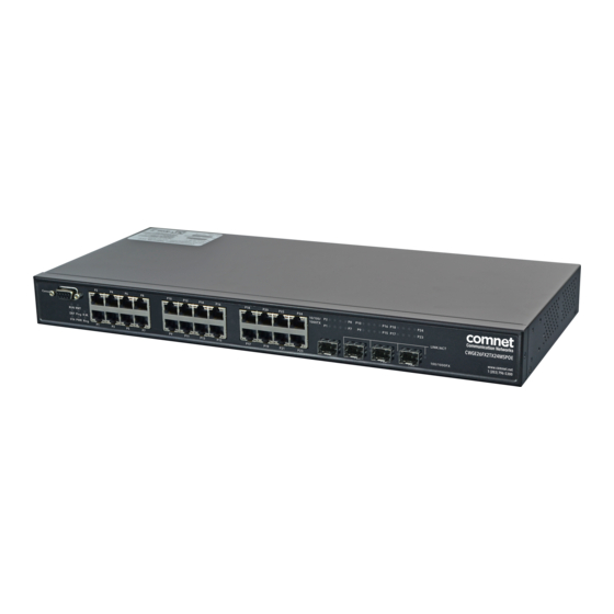
CWGE26FX2TX24MSPOE
(22) 10/100/1000 BASE-T(X) + (2) GIGABIT COMBO PORTS +
(2) 100/1000 BASE-FX WITH POWER OVER ETHERNET (POE+)
The ComNet
CWGE26FX2TX24MSPOE is an extended temperature commercial
™
grade Managed Ethernet Switch. It provides IEEE 802.3at PoE to twenty-four
10/100/1000BASE-T(X) two of which are also gigabit combo ports supporting
100/1000FX SFP Modules. A further two 100/1000FX SFP ports are also included.
Up to 400 watts of PoE power is available for distribution across all 24 electrical
ports. All SFP ports utilize ComNet SFPs for fiber and connector type and distance.
The CWGE26FX2TX24MSPOE is a redundant switch offering multiple Ethernet
redundancy protocols to protect your applications from network interruptions or
temporary malfunctions by redirecting transmission within the network.
Advertisement
Table of Contents

Related Manuals for Comnet CWGE26FX2TX24MSPOE


Summary of Contents for Comnet CWGE26FX2TX24MSPOE
- Page 1 100/1000FX SFP Modules. A further two 100/1000FX SFP ports are also included. Up to 400 watts of PoE power is available for distribution across all 24 electrical ports. All SFP ports utilize ComNet SFPs for fiber and connector type and distance. The CWGE26FX2TX24MSPOE is a redundant switch offering multiple Ethernet redundancy protocols to protect your applications from network interruptions or temporary malfunctions by redirecting transmission within the network.
-
Page 2: Table Of Contents
INSTALLATION AND OPERATION MANUAL CWGE26FX2TX24MSPOE Contents About This Guide Related Documentation About ComNet Website Support Safety Overview Introduction Software Features Hardware Features Hardware Overview Front Panel Rear Panel Rack mount kit assembly Ethernet Cables 1000/100BASE-TX/10BASE-T Pin Assignments Console Cable WEB Management... - Page 3 INSTALLATION AND OPERATION MANUAL CWGE26FX2TX24MSPOE DHCP Server Port Setting Port Trunk LACP Redundancy MSTP VLAN VLAN Setting Example SNMP Traffic Prioritization Multicast Security RADIUS Overview Warning System Warning Monitor and Diag Port Statistic System Log Information Cable Diagnostics SFP Monitor...
- Page 4 INSTALLATION AND OPERATION MANUAL CWGE26FX2TX24MSPOE TECH SUPPORT: 1.888.678.9427 INS_CWGE26FX2TX24MSPOE_REV– 5 Mar 2014 PAGE 4...
-
Page 5: About This Guide
» SFP Modules Data sheet About ComNet ComNet develops and markets the next generation of video solutions for the CCTV, defense, and homeland security markets. At the core of ComNet’s solutions are a variety of high-end video servers and the ComNet IVS software, which provide the industry with a standard platform for analytics and security management systems enabling leading performance, compact and cost effective solutions. -
Page 6: Overview
CWGE26FX2TX24MSPOE Overview Introduction The CWGE26FX2TX24MSPOE Gigabit managed redundant ring PoE Ethernet switch with 22x10/100/1000Base-T(X) IEEE802.3at PSE ports and two Gigabit combo IEEE802.3at PSE ports and 2x100/1000Base-X SFP ports supports Ethernet Redundancy protocol, C-Ring (recovery time < 30ms over 250 units of connection) and MSTP (RSTP/STP compatible). It can protect your mission-critical applications from network interruptions or temporary malfunctions with its fast recovery technology. -
Page 7: Software Features
INSTALLATION AND OPERATION MANUAL CWGE26FX2TX24MSPOE Software Features » C-Ring (recovery time < 30ms over 250 units of connection) » MSTP (RSTP/STP compatible) for Ethernet Redundancy » 24 ports PSE fully compliant with IEEE802.3at standard, providing up to 30 Watts per port »... -
Page 8: Hardware Features
INSTALLATION AND OPERATION MANUAL CWGE26FX2TX24MSPOE Hardware Features » 450 Watts power supply included » Operating Temperature: –10 to 60ºC » Storage Temperature: – 40 to 85ºC » Operating Humidity: 5% to 95%, non-condensing » 22 × 10/100/1000Base–T(X) » 2 × 100/1000Base-X SFP & 10/100/1000Base–T(X) COMBO »... -
Page 9: Hardware Overview
INSTALLATION AND OPERATION MANUAL CWGE26FX2TX24MSPOE Hardware Overview Front Panel The following table describes the labels on the CWGE26FX2TX24MSPOE Port Description Gigabit SFP ports 2 x 100/1000Base-X on SFP port Combo Ports 2 x 100/1000Base-X SFP & 10/100/1000Base-T(X) Combo Gigabit Ethernet Ports 22 x 10/100/1000Base–T(X) -
Page 10: Rear Panel
INSTALLATION AND OPERATION MANUAL CWGE26FX2TX24MSPOE Rear Panel The rear panel of CWGE26FX2TX24MSPOE 1. Power Switch 2. Power input for AC 100V~240V / 50~60Hz Rack mount kit assembly You can find the rack mount kit and the screws in the packing box. Please assembly the rack mount kit on the switch with screws as shown below: TECH SUPPORT: 1.888.678.9427... -
Page 11: Ethernet Cables
CWGE26FX2TX24MSPOE Ethernet Cables The CWGE26FX2TX24MSPOE series switches have standard Ethernet ports. According to the link type, the switches use CAT 3, 4, 5,5e UTP cables to connect to any other network device (PCs, servers, switches, routers, or hubs). Please refer to the following table for cable specifications. - Page 12 BI_DB- BI_DD+ BI_DD- The CWGE26FX2TX24MSPOE Series switches support auto MDI/MDI-X operation. You can use a straight-through cable to connect PC to switch. The following table below shows the 10BASE-T/ 100BASE-TX MDI and MDI-X port pin outs. 10/100 Base-T MDI/MDI-X pins assignment...
-
Page 13: Sfp
Switch B Console Cable CWGE26FX2TX24MSPOE Series switches can be managed via a console port located on the front of the switch. The DB-9 cable can be found in the package. You can connect them to PC via a RS-232 cable with DB-9 female connector and the other end (DB-9 male connector) connects to console port of switch. - Page 14 INSTALLATION AND OPERATION MANUAL CWGE26FX2TX24MSPOE DB-9 Male DB-9 Female RS-232 with DB-9 female PC pin out (male) assignment connector Pin #2 RD Pin #2 TD Pin #3 TD Pin #3 RD Pin #5 GD Pin #5 GD Male Connector Female Connector...
-
Page 15: Web Management
INSTALLATION AND OPERATION MANUAL CWGE26FX2TX24MSPOE WEB Management Attention: While installing and upgrading firmware, please remove physical loop connection first. DO NOT power off equipment while the firmware is upgrading! Configuration by Web Browser This section introduces the configuration by Web browser. - Page 16 INSTALLATION AND OPERATION MANUAL CWGE26FX2TX24MSPOE System Login 1. Launch Internet Explorer. 2. Type http:// and the IP address of the switch. Press “Enter”. 3. The login screen appears. Login screen 4. Key in the username and password. The default username and password is admin.
-
Page 17: Main Interface
INSTALLATION AND OPERATION MANUAL CWGE26FX2TX24MSPOE Main Interface Main interface TECH SUPPORT: 1.888.678.9427 INS_CWGE26FX2TX24MSPOE_REV– 5 Mar 2014 PAGE 17... -
Page 18: Basic Setting
INSTALLATION AND OPERATION MANUAL CWGE26FX2TX24MSPOE Basic Setting System Information The switch system information is provided here. System Information interface Label Description System Name An administratively assigned name for this managed node. By convention, this is the node’s fully-qualified domain name. A domain name is a text string drawn from the alphabet (A-Za-z), digits (0-9), minus sign (-). -
Page 19: Admin & Password
INSTALLATION AND OPERATION MANUAL CWGE26FX2TX24MSPOE Admin & Password This page allows you to configure the system password required to access the web pages or log in from CLI. Label Description Old Password Enter the current system password. If this is incorrect, the new password will not be set. -
Page 20: Auth Method
INSTALLATION AND OPERATION MANUAL CWGE26FX2TX24MSPOE Auth Method This page allows you to configure how a user is authenticated when he logs into the switch via one of the management client interfaces. Label Description Client The management client for which the configuration below applies. -
Page 21: Ip Setting
INSTALLATION AND OPERATION MANUAL CWGE26FX2TX24MSPOE IP Setting Configure the switch-managed IP information on this page. Label Description DHCP Client Enable the DHCP client by checking this box. If DHCP fails and the configured IP address is zero, DHCP will retry. If DHCP fails and the configured IP address is non- zero, DHCP will stop and the configured IP settings will be used. -
Page 22: Https
INSTALLATION AND OPERATION MANUAL CWGE26FX2TX24MSPOE HTTPS Label Description Mode Indicates the HTTPS mode operation. When the current connection is HTTPS, to apply HTTPS disabled mode operation will automatically redirect web browser to an HTTP connection. Possible modes are: Enabled: Enable HTTPS mode operation. -
Page 23: Lldp
INSTALLATION AND OPERATION MANUAL CWGE26FX2TX24MSPOE LLDP LLDP Configuration This page allows the user to inspect and configure the current LLDP port settings. Label Description Port The switch port number of the logical LLDP port. Mode Select LLDP mode. Disabled The switch will not send out LLDP information, and will drop LLDP information received from neighbors. - Page 24 INSTALLATION AND OPERATION MANUAL CWGE26FX2TX24MSPOE LLDP Neighbor Information This page provides a status overview for all LLDP neighbors. The displayed table contains a row for each port on which an LLDP neighbor is detected. The columns hold the following information:...
- Page 25 INSTALLATION AND OPERATION MANUAL CWGE26FX2TX24MSPOE Port Statistics This page provides an overview of all LLDP traffic. Two types of counters are shown. Global counters are counters that refer to the whole stack, switch, while local counters refer to counters for the currently selected switch.
- Page 26 INSTALLATION AND OPERATION MANUAL CWGE26FX2TX24MSPOE Local Counters Label Description Local Port The port on which LLDP frames are received or transmitted. Tx Frames The number of LLDP frames transmitted on the port. Rx Frames The number of LLDP frames received on the port.
-
Page 27: Backup/Restore Configuration
INSTALLATION AND OPERATION MANUAL CWGE26FX2TX24MSPOE Backup/Restore Configuration You can save/view or load the switch configuration. The configuration file is in XML format with a hierarchy of tags: Firmware Update This page facilitates an update of the firmware controlling the switch. - Page 28 INSTALLATION AND OPERATION MANUAL CWGE26FX2TX24MSPOE DHCP Dynamic Client List When the DHCP server function is activated, the system will collect the DHCP client information and display in here. DHCP Client List You can assign the specific IP address which is in the assigned dynamic IP range to the specific port.
-
Page 29: Port Setting
INSTALLATION AND OPERATION MANUAL CWGE26FX2TX24MSPOE Port Setting Port Control This page displays current port configurations. Ports can also be configured here. Label Description Port This is the logical port number for this row. Link The current link state is displayed graphically. Green indicates the link is up and red that it is down. - Page 30 INSTALLATION AND OPERATION MANUAL CWGE26FX2TX24MSPOE Power Control The Usage column shows the current percentage of the power consumption per port. The Configured column allows for changing the power savings mode parameters per port. Disabled: All power savings mechanisms disabled. ActiPHY: Link down power savings enabled.
-
Page 31: Port Trunk
INSTALLATION AND OPERATION MANUAL CWGE26FX2TX24MSPOE Port Trunk Trunk Configuration This page is used to configure the Aggregation hash mode and the aggregation group. Label Description Source MAC The Source MAC address can be used to calculate the destination port for the frame. - Page 32 INSTALLATION AND OPERATION MANUAL CWGE26FX2TX24MSPOE Label Description Group ID Indicates the group ID for the settings contained in the same row. Group ID “Normal” indicates there is no aggregation. Only one group ID is valid per port. Port Members Each switch port is listed for each group ID. Select a radio button to include a port in an aggregation, or clear the radio button to remove the port from the aggregation.
-
Page 33: Lacp
INSTALLATION AND OPERATION MANUAL CWGE26FX2TX24MSPOE LACP Port Configuration This page allows the user to inspect the current LACP port configurations, and possibly change them as well. Label Description Port Indicates the group ID for the settings contained in the same row. Group ID “Normal”... - Page 34 INSTALLATION AND OPERATION MANUAL CWGE26FX2TX24MSPOE LACP System Status This page provides a status overview for all LACP instances. Label Description Aggr ID The Aggregation ID associated with this aggregation instance. For LLAG the id is shown as ‘isid:aggr-id’ and for GLAGs as ‘aggr-id’...
- Page 35 INSTALLATION AND OPERATION MANUAL CWGE26FX2TX24MSPOE LACP Status This page provides a status overview for LACP status for all ports. Label Description Port The switch port number. LACP ‘Yes’ means that LACP is enabled and the port link is up. ‘No’ means that LACP is not enabled or that the port link is down.
- Page 36 INSTALLATION AND OPERATION MANUAL CWGE26FX2TX24MSPOE LACP Statistics This page provides an overview for LACP statistics for all ports. Label Description Port The switch port number LACP Shows how many LACP frames have been sent from each port Transmitted LACP Received Shows how many LACP frames have been received at each port.
-
Page 37: Redundancy
INSTALLATION AND OPERATION MANUAL CWGE26FX2TX24MSPOE Redundancy C-Ring C-Ring is one of the most powerful Ring technologies in the world. The recovery time of C-Ring is less than 30 ms. It can reduce unexpected damage caused by network topology change. C-Ring supports 3 different Ring topologies: Ring, Coupling Ring and Dual Homing. -
Page 38: Mstp
INSTALLATION AND OPERATION MANUAL CWGE26FX2TX24MSPOE MSTP Bridge Settings This page allows you to configure RSTP system settings. The settings are used by all RSTP Bridge instances in the Switch Stack. Label Description Protocol Version The STP protocol version setting. Valid values are STP, RSTP and MSTP. - Page 39 INSTALLATION AND OPERATION MANUAL CWGE26FX2TX24MSPOE MSTI Mapping This page allows the user to inspect the current STP MSTI bridge instance priority configurations, and possibly change them as well. Label Description Configuration The name identifying the VLAN to MSTI mapping. Bridges must share the name and...
- Page 40 INSTALLATION AND OPERATION MANUAL CWGE26FX2TX24MSPOE MSTI Priorities This page allows the user to inspect the current STP MSTI bridge instance priority configurations, and possibly change them as well. Label Description MSTI The bridge instance. The CIST is the default instance, which is always active.
- Page 41 INSTALLATION AND OPERATION MANUAL CWGE26FX2TX24MSPOE CIST Ports This page allows the user to inspect the current STP CIST port configurations, and possibly change them as well. This page contains settings for physical and aggregated ports. The aggregation settings are stack global.
- Page 42 INSTALLATION AND OPERATION MANUAL CWGE26FX2TX24MSPOE Restricted TCN If enabled, causes the port not to propagate received topology change notifications and topology changes to other ports. If set it can cause temporary loss of connectivity after changes in a spanning trees active topology as a result of persistent incorrectly learned station location information.
- Page 43 INSTALLATION AND OPERATION MANUAL CWGE26FX2TX24MSPOE MSTI Ports This page allows the user to inspect the current STP MSTI port configurations, and possibly change them as well. A MSTI port is a virtual port, which is instantiated separately for each active CIST (physical) port for each MSTI instance configured and applicable for the port.
-
Page 44: Stp
INSTALLATION AND OPERATION MANUAL CWGE26FX2TX24MSPOE STP Bridges This page provides a status overview for all STP bridge instances. The displayed table contains a row for each STP bridge instance, where the column displays the following information: Label Description MSTI The Bridge Instance. This is also a link to the STP Detailed Bridge Status. - Page 45 INSTALLATION AND OPERATION MANUAL CWGE26FX2TX24MSPOE STP Port Status This page displays the STP CIST port status for port physical ports in the currently selected switch. Label Description Port The switch port number of the logical STP port. CIST Role The current STP port role of the CIST port. The port role can be one of the following values: AlternatePort BackupPort RootPort DesignatedPort.
- Page 46 INSTALLATION AND OPERATION MANUAL CWGE26FX2TX24MSPOE STP Statistics This page displays the RSTP port statistics counters for bridge ports in the currently selected switch. Label Description Port The switch port number of the logical RSTP port. RSTP The number of RSTP Configuration BPDU’s received/transmitted on the port.
-
Page 47: Vlan
INSTALLATION AND OPERATION MANUAL CWGE26FX2TX24MSPOE VLAN VLAN Membership Configuration The VLAN membership configuration for the selected stack switch unit switch can be monitored and modified here. Up to 64 VLANs are supported. This page allows for adding and deleting VLANs as well as adding and deleting port members of each VLAN. -
Page 48: Vlan Port Configuration
INSTALLATION AND OPERATION MANUAL CWGE26FX2TX24MSPOE VLAN Port Configuration TECH SUPPORT: 1.888.678.9427 INS_CWGE26FX2TX24MSPOE_REV– 5 Mar 2014 PAGE 48... - Page 49 INSTALLATION AND OPERATION MANUAL CWGE26FX2TX24MSPOE Label Description Ethertype for This field specifies the ether type used for Custom S-ports. This is a global setting for customer S-Ports all the Custom S-ports. Port This is the logical port number of this row.
- Page 50 INSTALLATION AND OPERATION MANUAL CWGE26FX2TX24MSPOE How to use Unaware / C-Port / S-Port / S-Custom-Port Port can be one of the following types: Unaware, C-port, S-port, and S-custom-port. Ingress action Egress action Unaware When the port received untagged frames, an...
- Page 51 INSTALLATION AND OPERATION MANUAL CWGE26FX2TX24MSPOE Packet Packet No VLAN No VLAN QinQ Packet Packet CWGE26FX2TX24MSPOE VID: 5 VID: 5 Unaware VID: PVID TPID: 8100 TPID: 8100 TPID: 8100 Packet Packet VID: 5 Discarded TPID: 88A8 Packet Packet No VLAN No VLAN...
-
Page 52: Vlan Setting Example
INSTALLATION AND OPERATION MANUAL CWGE26FX2TX24MSPOE VLAN Setting Example VLAN Access Mode Setting VLAN 10 VLAN 10 VLAN Trunk VLAN Trunk 10,20 10,20 CWGE26FX2TX24MSPOE CWGE26FX2TX24MSPOE CWGE26FX2TX24MSPOE Switch A Switch B Switch C VLAN 20 VLAN 20 In the topology above, for Switch A,... - Page 53 INSTALLATION AND OPERATION MANUAL CWGE26FX2TX24MSPOE VLAN 1Q Trunk mode VLAN 10 VLAN 10 VLAN Trunk VLAN Trunk 10,20 10,20 CWGE26FX2TX24MSPOE CWGE26FX2TX24MSPOE CWGE26FX2TX24MSPOE Switch A Switch B Switch C VLAN 20 VLAN 20 In the topology above, for Switch B, Port 1 = VLAN 1Qtrunk mode = tagged 10,20...
-
Page 54: Vlan Qinq Mode
INSTALLATION AND OPERATION MANUAL CWGE26FX2TX24MSPOE VLAN Hybrid mode To set Port 1 VLAN Hybrid mode = untagged 10 Tagged 10,20 Configure the VLAN for the Switch as shown VLAN QinQ mode Below is an example of the VLAN QinQ Mode, which is typically used in an environment with unknown VLAN. - Page 55 INSTALLATION AND OPERATION MANUAL CWGE26FX2TX24MSPOE VLAN Management VLAN ID Setting If Management VLAN is set, only the same VLAN ID port can control the switch. TECH SUPPORT: 1.888.678.9427 INS_CWGE26FX2TX24MSPOE_REV– 5 Mar 2014 PAGE 55...
- Page 56 INSTALLATION AND OPERATION MANUAL CWGE26FX2TX24MSPOE Private VLAN The Private VLAN membership configurations for the switch can be monitored and modified here. Private VLANs can be added or deleted here. Port members of each Private VLAN can be added or removed here. Private VLANs are based on the source port mask, and there are no connections to VLANs.
-
Page 57: Snmp
INSTALLATION AND OPERATION MANUAL CWGE26FX2TX24MSPOE Label Description Port Number A check box is provided for each port of a private VLAN. When checked, port isolation is enabled for that port. When unchecked, port isolation is disabled for that port. By default, port isolation is disabled for all ports. - Page 58 INSTALLATION AND OPERATION MANUAL CWGE26FX2TX24MSPOE Engine ID Indicates the SNMPv3 engine ID. The string must contain an even number between 10 and 64 hexadecimal digits, but all-zeros and all-’F’s are not allowed. Change of the Engine ID will clear all original local users.
- Page 59 INSTALLATION AND OPERATION MANUAL CWGE26FX2TX24MSPOE Trap Inform Indicates the SNMP trap inform timeout. The allowed range is 0 to 2147. Timeout (seconds) Trap Inform Indicates the SNMP trap inform retry times. The allowed range is 0 to 255. Retry Times Trap Probe Indicates the SNMP trap probe security engine ID mode of operation.
- Page 60 INSTALLATION AND OPERATION MANUAL CWGE26FX2TX24MSPOE SNMP-Users Configure SNMPv3 users table on this page. The entry index keys are Engine ID and User Name. Label Description Delete Check to delete the entry. It will be deleted during the next save. Engine ID An octet string identifying the engine ID that this entry should belong to.
- Page 61 INSTALLATION AND OPERATION MANUAL CWGE26FX2TX24MSPOE SNMP-Groups Configure SNMPv3 groups table on this page. The entry index keys are Security Model and Security Name. Label Description Delete Check to delete the entry. It will be deleted during the next save. Security Model Indicates the security model that this entry should belong to.
- Page 62 INSTALLATION AND OPERATION MANUAL CWGE26FX2TX24MSPOE View Type Indicates the view type that this entry should belong to. Possible view types are: included: An optional flag to indicate that this view subtree should be included. excluded: An optional flag to indicate that this view subtree should be excluded.
-
Page 63: Traffic Prioritization
INSTALLATION AND OPERATION MANUAL CWGE26FX2TX24MSPOE Traffic Prioritization Storm Control There is a unicast storm rate control, multicast storm rate control, and a broadcast storm rate control. These only affect flooded frames, i.e. frames with a (VLAN ID, DMAC) pair not present on the MAC Address table. - Page 64 INSTALLATION AND OPERATION MANUAL CWGE26FX2TX24MSPOE Port Classification QoS is an acronym for Quality of Service. It is a method to guarantee a bandwidth relationship between individual applications or protocols. Label Description Port The port number for which the configuration below applies QoS Class Controls the default QoS class.
- Page 65 INSTALLATION AND OPERATION MANUAL CWGE26FX2TX24MSPOE DP level Controls the default Drop Precedence Level. All frames are classified to a DP level. If the port is VLAN aware and the frame is tagged, then the frame is classified to a DP level that is equal to the DEI value in the tag.
- Page 66 INSTALLATION AND OPERATION MANUAL CWGE26FX2TX24MSPOE Port Tag Remarking This page provides an overview of QoS Egress Port Tag Remarking for all switch ports. Label Description Port The logical port for the settings contained in the same row. Click on the port number in order to configure tag remarking Mode Shows the tag remarking mode for this port.
- Page 67 INSTALLATION AND OPERATION MANUAL CWGE26FX2TX24MSPOE Port DSCP This page allows you to configure the basic QoS Port DSCP Configuration settings for all switch ports. Label Description Port The Port column shows the list of ports for which you can configure dscp ingress and egress settings.
- Page 68 INSTALLATION AND OPERATION MANUAL CWGE26FX2TX24MSPOE Egress Port Egress Rewriting can be one of – • Disable: No Egress rewrite. • Enable: Rewrite enabled without remapping. • Remap DP Unaware: DSCP from analyzer is remapped and frame is remarked with remapped DSCP value. The remapped DSCP value is always taken from the ‘DSCP Translation->Egress Remap DP0’...
- Page 69 INSTALLATION AND OPERATION MANUAL CWGE26FX2TX24MSPOE Queue Policing This page allows you to configure the Queue Policer settings for all switch ports. Label Description Port The port number for which the configuration below applies. Enable(E) Controls whether the queue policer is enabled on this switch port.
- Page 70 INSTALLATION AND OPERATION MANUAL CWGE26FX2TX24MSPOE Port Shaping This page provides an overview of QoS Egress Port Shapers for all switch ports. Label Description Port The logical port for the settings contained in the same row. Click on the port number in order to configure the shapers.
- Page 71 INSTALLATION AND OPERATION MANUAL CWGE26FX2TX24MSPOE DSCP Translation This page allows you to configure the basic QoS DSCP Translation settings for all switches. DSCP translation can be done in Ingress or Egress. Label Description DSCP Maximum number of supported DSCP values are 64 and valid DSCP value ranges from 0 to 63.
-
Page 72: Dscp Classification
INSTALLATION AND OPERATION MANUAL CWGE26FX2TX24MSPOE DSCP Classification This page allows you to configure the mapping of QoS class and Drop Precedence Level to DSCP value. Label Description QoS Class Actual QoS class Actual Drop Precedence Level. DSCP Select the classified DSCP value (0-63). - Page 73 INSTALLATION AND OPERATION MANUAL CWGE26FX2TX24MSPOE QoS Control List This page allows to edit|insert a single QoS Control Entry at a time. A QCE consists of several parameters. These parameters vary according to the frame type that you select. Label Description Port Members Check the checkbox button to include the port in the QCL entry.
- Page 74 INSTALLATION AND OPERATION MANUAL CWGE26FX2TX24MSPOE 3. LLC SSAP Address Valid SSAP(Source Service Access Point) can vary from 0x00 to 0xFF or ‘Any’, the default value is ‘Any’. DSAP Address Valid DSAP(Destination Service Access Point) can vary from 0x00 to 0xFF or ‘Any’, the default value is ‘Any’.
- Page 75 INSTALLATION AND OPERATION MANUAL CWGE26FX2TX24MSPOE QoS Counters This page provides statistics for the different queues for all switch ports. Label Description Port The logical port for the settings contained in the same row. There are 8 QoS queues per port. Q0 is the lowest priority queue.
- Page 76 INSTALLATION AND OPERATION MANUAL CWGE26FX2TX24MSPOE QCL Status This page shows the QCL status by different QCL users. Each row describes the QCE that is defined. It is a conflict if a specific QCE is not applied to the hardware due to hardware limitations.
-
Page 77: Multicast
INSTALLATION AND OPERATION MANUAL CWGE26FX2TX24MSPOE Multicast IGMP Snooping This page provides IGMP Snooping related configuration. Label Description Snooping Enable the Global IGMP Snooping. Enabled Unregistered Enable unregistered IPMC traffic flooding. IPMCv4Flooding enabled Router Port Specify which ports act as router ports. A router port is a port on the Ethernet switch that leads towards the Layer 3 multicast device or IGMP querier. - Page 78 INSTALLATION AND OPERATION MANUAL CWGE26FX2TX24MSPOE IGMP Snooping – VLAN Configuration Each page shows up to 99 entries from the VLAN table, default being 20, selected through the “entries per page” input field. When first visited, the web page will show the first 20 entries from the beginning of the VLAN Table.
- Page 79 INSTALLATION AND OPERATION MANUAL CWGE26FX2TX24MSPOE IGMP Snooping Status This page provides IGMP Snooping status. Label Description VLAN ID The VLAN ID of the entry. Querier Version Working Querier Version currently. Host Version Working Host Version currently. Querier Status Show the Querier status is “ACTIVE” or “IDLE”.
- Page 80 INSTALLATION AND OPERATION MANUAL CWGE26FX2TX24MSPOE IGMP Snooping Groups Information Entries in the IGMP Group Table are shown on this page. The IGMP Group Table is sorted first by VLAN ID, and then by group. Label Description VLAN ID VLAN ID of the group.
-
Page 81: Security
INSTALLATION AND OPERATION MANUAL CWGE26FX2TX24MSPOE Security Ports Configure the ACL parameters (ACE) of each switch port. These parameters will affect frames received on a port unless the frame matches a specific ACE. Label Description Port The logical port for the settings contained in the same row. - Page 82 INSTALLATION AND OPERATION MANUAL CWGE26FX2TX24MSPOE Rate Limiters Configure the rate limiter for the ACL of the switch. Label Description Rate Limiter ID The rate limiter ID for the settings contained in the same row. Rate The rate unit is packet per second (pps), configure the rate as 1, 2, 4, 8, 16, 32, 64, 128, 256, 512, 1K, 2K, 4K, 8K, 16K, 32K, 64K, 128K, 256K, 512K, or 1024K.
- Page 83 INSTALLATION AND OPERATION MANUAL CWGE26FX2TX24MSPOE ACL Control List Configure an ACE (Access Control Entry) on this page. An ACE consists of several parameters. These parameters vary according to the frame type that you select. First select the ingress port for the ACE, and then select the frame type. Different parameter options are displayed depending on the frame type that you selected.
- Page 84 INSTALLATION AND OPERATION MANUAL CWGE26FX2TX24MSPOE Logging Specify the logging operation of the ACE. The allowed values are: Enabled: Frames matching the ACE are stored in the System Log. Disabled: Frames matching the ACE are not logged. Please note that the System Log memory size and logging rate is limited.
-
Page 85: Aaa
INSTALLATION AND OPERATION MANUAL CWGE26FX2TX24MSPOE Common Server Configuration This page allows you to configure the Authentication Servers Label Description Timeout The Timeout, which can be set to a number between 3 and 3600 seconds, is the maximum time to wait for a reply from a server. - Page 86 INSTALLATION AND OPERATION MANUAL CWGE26FX2TX24MSPOE RADIUS Authentication Server Configuration The table has one row for each RADIUS Authentication Server and a number of columns, which are: Label Description The RADIUS Authentication Server number for which the configuration below applies. Enabled Enable the RADIUS Authentication Server by checking this box.
-
Page 87: Radius Overview
INSTALLATION AND OPERATION MANUAL CWGE26FX2TX24MSPOE RADIUS Overview This page provides an overview of the status of the RADIUS servers configurable on the Authentication configuration page. RADIUS Authentication Servers Label Description The RADIUS server number. Click to navigate to detailed statistics for this server. - Page 88 INSTALLATION AND OPERATION MANUAL CWGE26FX2TX24MSPOE RADIUS Accounting Servers Label Description The RADIUS server number. Click to navigate to detailed statistics for this server. IP Address The IP address and UDP port number (in <IP Address>:<UDP Port> notation) of this server.
- Page 89 INSTALLATION AND OPERATION MANUAL CWGE26FX2TX24MSPOE Label Description Packet Counters RADIUS authentication server packet counter. There are seven receive and four transmit counters. Other Info This section contains information about the state of the server and the latest round-trip time. TECH SUPPORT: 1.888.678.9427...
- Page 90 INSTALLATION AND OPERATION MANUAL CWGE26FX2TX24MSPOE Label Description Packet Counters RADIUS accounting server packet counter. There are five receive and four transmit counters. Other Info This section contains information about the state of the server and the latest TECH SUPPORT: 1.888.678.9427...
- Page 91 INSTALLATION AND OPERATION MANUAL CWGE26FX2TX24MSPOE NAS(802.1x) This page allows you to configure the IEEE 802.1X and MAC-based authentication system and port settings. The IEEE 802.1X standard defines a port-based access control procedure that prevents unauthorized access to a network by requiring users to first submit credentials for authentication.
- Page 92 INSTALLATION AND OPERATION MANUAL CWGE26FX2TX24MSPOE Overview of MAC-Based Authentication Unlike 802.1X, MAC-based authentication is not a standard, but merely a best-practices method adopted by the industry. In MAC-based authentication, users are called clients, and the switch acts as the supplicant on behalf of clients. The initial frame (any kind of frame) sent by a client is snooped by the switch, which in turn uses the client’s MAC address as both username and...
- Page 93 INSTALLATION AND OPERATION MANUAL CWGE26FX2TX24MSPOE Label Description Mode Indicates if 802.1X and MAC-based authentication is globally enabled or disabled on the switch. If globally disabled, all ports are allowed forwarding of frames. Reauthentication If checked, clients are reauthenticated after the interval specified by the Enabled Reauthentication Period.
- Page 94 INSTALLATION AND OPERATION MANUAL CWGE26FX2TX24MSPOE Admin State If NAS is globally enabled, this selection controls the port’s authentication mode. The following modes are available: Force Authorized In this mode, the switch will send one EAPOL Success frame when the port link comes up, and any client on the port will be allowed network access without authentication.
- Page 95 INSTALLATION AND OPERATION MANUAL CWGE26FX2TX24MSPOE Port State The current state of the port. It can undertake one of the following values: Globally Disabled: NAS is globally disabled. Link Down: NAS is globally enabled, but there is no link on the port.
- Page 96 INSTALLATION AND OPERATION MANUAL CWGE26FX2TX24MSPOE Last ID The user name (supplicant identity) carried in the most recently received Response Identity EAPOL frame for EAPOL-based authentication, and the source MAC address from the most recently received frame from a new client for MAC-based authentication.
- Page 97 INSTALLATION AND OPERATION MANUAL CWGE26FX2TX24MSPOE Backend Server These backend (RADIUS) frame counters are available for the following administrative Counters states: • 802.1X • MAC-based Auth. Last Supplicant/ Information about the last supplicant/client that attempted to authenticate. This Client Info information is available for the following administrative states: •...
-
Page 98: Warning
INSTALLATION AND OPERATION MANUAL CWGE26FX2TX24MSPOE Warning Fault Alarm When any selected fault event is happened, the Fault LED in switch panel will light up and the electric relay will signal at the same time. TECH SUPPORT: 1.888.678.9427 INS_CWGE26FX2TX24MSPOE_REV– 5 Mar 2014 PAGE 98... -
Page 99: System Warning
INSTALLATION AND OPERATION MANUAL CWGE26FX2TX24MSPOE System Warning SYSLOG Setting The SYSLOG is a protocol to transmit event notification messages across networks. Please refer to RFC 3164 – The BSD SYSLOG Protocol System Warning – SYSLOG Setting interface The following table describes the labels in this screen. - Page 100 INSTALLATION AND OPERATION MANUAL CWGE26FX2TX24MSPOE Event Selection SYSLOG and SMTP are the two warning methods that supported by the system. Check the corresponding box to enable system event warning method you wish to choose. Please note that the checkbox cannot be checked when SYSLOG or SMTP is disabled.
-
Page 101: Monitor And Diag
INSTALLATION AND OPERATION MANUAL CWGE26FX2TX24MSPOE Monitor and Diag MAC Table Configuration The MAC Address Table is configured on this page. Set timeouts for entries in the dynamic MAC Table and configure the static MAC table here. Aging Configuration By default, dynamic entries are removed from the MAC after 300 seconds. This removal is also called aging. - Page 102 INSTALLATION AND OPERATION MANUAL CWGE26FX2TX24MSPOE MAC Table Learning If the learning mode for a given port is grayed out, another module is in control of the mode, so that it cannot be changed by the user. An example of such a module is the MAC-Based Authentication under 802.1X.
- Page 103 INSTALLATION AND OPERATION MANUAL CWGE26FX2TX24MSPOE MAC Table Each page shows up to 999 entries from the MAC table, default being 20, selected through the “entries per page” input field. When first visited, the web page will show the first 20 entries from the beginning of the MAC Table.
-
Page 104: Port Statistic
INSTALLATION AND OPERATION MANUAL CWGE26FX2TX24MSPOE Port Statistic Traffic Overview This page provides an overview of general traffic statistics for all switch ports. Label Description Port The logical port for the settings contained in the same row. Packets The number of received and transmitted packets per port. - Page 105 INSTALLATION AND OPERATION MANUAL CWGE26FX2TX24MSPOE Detailed Statistics This page provides detailed traffic statistics for a specific switch port. Use the port select box to select which switch port details to display. The displayed counters are the totals for receive and transmit, the size counters for receive and transmit, and the error counters for receive and transmit.
- Page 106 INSTALLATION AND OPERATION MANUAL CWGE26FX2TX24MSPOE Short frames are frames that are smaller than 64 bytes. Long frames are frames that are longer than the configured maximum frame length for this port. Port Monitoring Configure port Mirroring on this page. To debug network problems, selected traffic can be copied, or mirrored, to a mirror port where a frame analyzer can be attached to analyze the frame flow.
-
Page 107: System Log Information
INSTALLATION AND OPERATION MANUAL CWGE26FX2TX24MSPOE System Log Information The switch system log information is provided here. Label Description The ID (>= 1) of the system log entry. Level The level of the system log entry. The following level types are supported: Info: Information level of the system log. -
Page 108: Cable Diagnostics
INSTALLATION AND OPERATION MANUAL CWGE26FX2TX24MSPOE Cable Diagnostics This page is used for running the VeriPHY Cable Diagnostics. Press Start to run the diagnostics. This will take approximately 5 seconds. If all ports are selected, this can take approximately 15 seconds. When completed, the page refreshes automatically, and you can view the cable diagnostics results in the cable status table. -
Page 109: Sfp Monitor
INSTALLATION AND OPERATION MANUAL CWGE26FX2TX24MSPOE SFP Monitor DDM function, can pass SFP module which supports DDM function, measure the temperature of the apparatus and manage and set up event alarm module through DDM WEB TECH SUPPORT: 1.888.678.9427 INS_CWGE26FX2TX24MSPOE_REV– 5 Mar 2014 PAGE 109... -
Page 110: Ping
INSTALLATION AND OPERATION MANUAL CWGE26FX2TX24MSPOE Ping This page allows you to issue ICMP PING packets to troubleshoot IP connectivity issues. After you press Start, 5 ICMP packets are transmitted, and the sequence number and roundtrip time are displayed upon reception of a reply. The page refreshes automatically until responses to all packets are received, or until a timeout occurs. -
Page 111: Syncronization-Ptp
INSTALLATION AND OPERATION MANUAL CWGE26FX2TX24MSPOE Syncronization-PTP Overview of MAC-Based Authentication This page allows the user to configure and inspect the current PTP clock settings. PTP External Clock Mode Label Description One_pps_mode This Selection box will allow you to select the One_pps_mode configuration. - Page 112 INSTALLATION AND OPERATION MANUAL CWGE26FX2TX24MSPOE PTP Clock Configuration Label Description Delete Check this box and click on ‘Save’ to delete the clock instance. Clock Instance Indicates the Instance of a particular Clock Instance [0..3]. Click on the Clock Instance number to edit the Clock details.
-
Page 113: Poe Configuration
INSTALLATION AND OPERATION MANUAL CWGE26FX2TX24MSPOE PoE Configuration PoE is an acronym for Power Over Ethernet. Power Over Ethernet is used to transmit electrical power, to remote devices over standard Ethernet cable. It could for example be used for powering IP telephones, wireless LAN access points and other equipment, where it would be difficult or expensive to connect the equipment to main power supply. - Page 114 INSTALLATION AND OPERATION MANUAL CWGE26FX2TX24MSPOE Power There are 2 modes for configuring when to shut down the ports: Management 1. Actual Consumption: In this mode the ports are shut down when the actual power Mode consumption for all ports exceeds the amount of power that the power supply can deliver or if the actual power consumption for a given port exceeds the reserved power for that port.
-
Page 115: Status
INSTALLATION AND OPERATION MANUAL CWGE26FX2TX24MSPOE Status This page allows the user to inspect the current status for all PoE ports. Label Description Local Port This is the logical port number for this row. PD Class Each PD is classified according to a class that defines the maximum power the PD will use. -
Page 116: Factory Defaults
INSTALLATION AND OPERATION MANUAL CWGE26FX2TX24MSPOE Factory Defaults You can reset the configuration of the stack switch on this page. Only the IP configuration is retained. Label Description Click to reset the configuration to Factory Defaults. Click to return to the Port State page without resetting the... -
Page 117: Command Line Interface Management
Command Line Interface Management About CLI Management In addition to WEB-base management, the CWGE26FX2TX24MSPOE also supports CLI management. You can use console or telnet to management the switch by CLI. CLI Management by RS-232 Serial Console (115200, 8, none, 1, none) Before Configuring by RS-232 serial console, use an DB-9-M to DB-9-F cable to connect the switches’... - Page 118 INSTALLATION AND OPERATION MANUAL CWGE26FX2TX24MSPOE Step 2. Input a name for new connection Step 3. Select to use COM port number TECH SUPPORT: 1.888.678.9427 INS_CWGE26FX2TX24MSPOE_REV– 5 Mar 2014 PAGE 118...
- Page 119 INSTALLATION AND OPERATION MANUAL CWGE26FX2TX24MSPOE Step 4. The COM port properties setting, 115200 for baud rate, 8 for Data bits, None for Parity, 1 for Stop bits and none for Flow control. Step 5. The Console login screen will appear. Use the keyboard to enter the Username and Password (these are the same as the credentials for Web Browser), and then press Enter.
- Page 120 INSTALLATION AND OPERATION MANUAL CWGE26FX2TX24MSPOE CLI Management by Telnet Users can use “TELNET” to configure the switches. The default value is as below: IP Address: 192.168.10.1 Subnet Mask: 255.255.255.0 Default Gateway: 192.168.10.254 User Name: admin Password: admin Follow the steps below to access the console via Telnet.
-
Page 121: Commander Groups
INSTALLATION AND OPERATION MANUAL CWGE26FX2TX24MSPOE Commander Groups System Configuration [all] [<port_list>] Reboot Restore Default [keep_ip] Contact [<contact>] Name [<name>] System> Location [<location>] Description [<description>] Password <password> Username [<username>] Timezone [<offset>] Log [<log_id>] [all|info|warning|error] [clear] TECH SUPPORT: 1.888.678.9427 INS_CWGE26FX2TX24MSPOE_REV– 5 Mar 2014 PAGE 121... - Page 122 INSTALLATION AND OPERATION MANUAL CWGE26FX2TX24MSPOE Configuration DHCP [enable|disable] IP> Setup [<ip_addr>] [<ip_mask>] [<ip_router>] [<vid>] Ping <ip_addr_string> [<ping_length>] SNTP [<ip_addr_string>] Port Configuration [<port_list>] [up|down] State [<port_list>] [enable|disable] Mode [<port_list>] [auto|10hdx|10fdx|100hdx|100fdx|1000fdx|sfp_auto_ams] Flow Control [<port_list>] [enable|disable] MaxFrame [<port_list>] [<max_frame>] Port> Power [<port_list>] [enable|disable|actiphy|dynamic] Excessive [<port_list>] [discard|restart]...
- Page 123 INSTALLATION AND OPERATION MANUAL CWGE26FX2TX24MSPOE VLAN Configuration [<port_list>] PVID [<port_list>] [<vid>|none] FrameType [<port_list>] [all|tagged|untagged] IngressFilter [<port_list>] [enable|disable] tx_tag [<port_list>] [untag_pvid|untag_all|tag_all] PortType [<port_list>] [unaware|c-port|s-port|s-custom-port] EtypeCustomSport [<etype>] Add <vid>|<name> [<ports_list>] VLAN> Forbidden Add <vid>|<name> [<port_list>] Delete <vid>|<name> Forbidden Delete <vid>|<name> Forbidden Lookup [<vid>] [(name <name>)] Lookup [<vid>] [(name <name>)] [combined|static|nas|all]...
- Page 124 INSTALLATION AND OPERATION MANUAL CWGE26FX2TX24MSPOE Security Switch Password <password> Auth Authentication Security/switch> SSH Secure Shell HTTPS Hypertext Transfer Protocol over Secure Socket Layer RMON Remote Network Monitoring Security Switch Authentication Configuration Security/switch/auth> Method [console|telnet|ssh|web] [none|local|radius] [enable|disable] Security Switch SSH Configuration Security/switch/ssh>...
- Page 125 INSTALLATION AND OPERATION MANUAL CWGE26FX2TX24MSPOE Security Network Psec Port Security Status NAS Network Access Server (IEEE 802.1X) Security/Network> ACL Access Control List DHCP Dynamic Host Configuration Protocol Security Network Psec Switch [<port_list>] Security/Network/ Psec> Port [<port_list>] Security Network NAS Configuration [<port_list>] Mode [enable|disable] State [<port_list>] [auto|authorized|unauthorized|macbased]...
- Page 126 INSTALLATION AND OPERATION MANUAL CWGE26FX2TX24MSPOE Security Network ACL Configuration [<port_list>] Action [<port_list>] [permit|deny] [<rate_limiter>][<port_redirect>] [<mirror>] [<logging>] [<shutdown>] Policy [<port_list>] [<policy>] Rate [<rate_limiter_list>] [<rate_unit>] [<rate>] Add [<ace_id>] [<ace_id_next>][(port <port_list>)] [(policy <policy> <policy_ bitmask>)][<tagged>] [<vid>] [<tag_prio>] [<dmac_type>][(etype [<etype>] [<smac>] [<dmac>]) | (arp [<sip>] [<dip>] [<smac>] [<arp_opcode>] [<arp_ flags>]) | (ip [<sip>] [<dip>] [<protocol>] [<ip_flags>]) | (icmp [<sip>] [<dip>]...
- Page 127 INSTALLATION AND OPERATION MANUAL CWGE26FX2TX24MSPOE Configuration Version [<stp_version>] Non-certified release, v Txhold [<holdcount>]lt 15:15:15, Dec 6 2007 MaxAge [<max_age>] FwdDelay [<delay>] bpduFilter [enable|disable] bpduGuard [enable|disable] recovery [<timeout>] CName [<config-name>] [<integer>] Status [<msti>] [<port_list>] Msti Priority [<msti>] [<priority>] Msti Map [<msti>] [clear] Msti Add <msti>...
- Page 128 INSTALLATION AND OPERATION MANUAL CWGE26FX2TX24MSPOE LACP Configuration [<port_list>] Mode [<port_list>] [enable|disable] Key [<port_list>] [<key>] LACP> Role [<port_list>] [active|passive] Status [<port_list>] Statistics [<port_list>] [clear] LLDP Configuration [<port_list>] Mode [<port_list>] [enable|disable] LLDP> Statistics [<port_list>] [clear] Info [<port_list>] Configuration [<port_list>] Mode [<port_list>] [disabled|poe|poe+] Priority [<port_list>] [low|high|critical]...
- Page 129 INSTALLATION AND OPERATION MANUAL CWGE26FX2TX24MSPOE DSCP Map [<dscp_list>] [<class>] [<dpl>] DSCP Translation [<dscp_list>] [<trans_dscp>] DSCP Trust [<dscp_list>] [enable|disable] DSCP Classification Mode [<dscp_list>] [enable|disable] DSCP Classification Map [<class_list>] [<dpl_list>] [<dscp>] DSCP EgressRemap [<dscp_list>] [<dpl_list>] [<dscp>] Storm Unicast [enable|disable] [<packet_rate>] Storm Multicast [enable|disable] [<packet_rate>] Storm Broadcast [enable|disable] [<packet_rate>]...
- Page 130 INSTALLATION AND OPERATION MANUAL CWGE26FX2TX24MSPOE IGMP Configuration [<port_list>] Mode [enable|disable] State [<vid>] [enable|disable] Querier [<vid>] [enable|disable] IGMP> Fastleave [<port_list>] [enable|disable] Router [<port_list>] [enable|disable] Flooding [enable|disable] Groups [<vid>] Status [<vid>] Configuration [<port_list>] Action [<port_list>] [permit|deny] [<rate_limiter>] [<port_copy>][<logging>] [<shutdown>] Policy [<port_list>] [<policy>] Rate [<rate_limiter_list>] [<packet_rate>]...
- Page 131 INSTALLATION AND OPERATION MANUAL CWGE26FX2TX24MSPOE Firmware Firmware> Load <ip_addr_string> <file_name> SNMP Trap Inform Retry Times [<retries>] Trap Probe Security Engine ID [enable|disable] Trap Security Engine ID [<engineid>] Trap Security Name [<security_name>] Engine ID [<engineid>] Community Add <community> [<ip_addr>] [<ip_mask>] Community Delete <index>...
- Page 132 INSTALLATION AND OPERATION MANUAL CWGE26FX2TX24MSPOE Configuration [<clockinst>] PortState <clockinst> [<port_list>] [enable|disable|internal] ClockCreate <clockinst> [<devtype>] [<twostep>] [<protocol>] [<oneway>] [<clockid>] [<tag_enable>] [<vid>] [<prio>] ClockDelete <clockinst> [<devtype>] DefaultDS <clockinst> [<priority1>] [<priority2>] [<domain>] CurrentDS <clockinst> ParentDS <clockinst> Timingproperties <clockinst> [<utcoffset>] [<valid>] [<leap59>] [<leap61>] [<timetrac>] [<freqtrac>] [<ptptimescale>] [<timesource>] PTP PortDataSet <clockinst>...
- Page 133 INSTALLATION AND OPERATION MANUAL CWGE26FX2TX24MSPOE IPMC Configuration [igmp] Mode [igmp] [enable|disable] Flooding [igmp] [enable|disable] VLAN Add [igmp] <vid> VLAN Delete [igmp] <vid> State [igmp] [<vid>] [enable|disable] IPMC> Querier [igmp] [<vid>] [enable|disable] Fastleave [igmp] [<port_list>] [enable|disable] Router [igmp] [<port_list>] [enable|disable] Status [igmp] [<vid>] Groups [igmp] [<vid>]...
- Page 134 INSTALLATION AND OPERATION MANUAL CWGE26FX2TX24MSPOE Ring Mode [enable|disable] Master [enable|disable] 1stRingPort [<port>] 2ndRingPort [<port>] Ring> Couple Mode [enable|disable] Couple Port [<port>] Dualhoming Mode [enable|disable] Dualhoming Port [<port>] syslog [enable|disable] SFP> temp [<temperature>] Info TECH SUPPORT: 1.888.678.9427 INS_CWGE26FX2TX24MSPOE_REV– 5 Mar 2014 PAGE 134...
-
Page 135: Technical Specifications
INSTALLATION AND OPERATION MANUAL CWGE26FX2TX24MSPOE Technical Specifications ComNet Switch Model CWGE26FX2TX24MSPOE Physical Ports 10/100/1000Base-T(X) with PSE Ports in RJ45 Auto MDI/MDIX Gigabit Combo port with 10/100/1000Base-T(X) PSE and 100/1000Base-X SFP ports 100/1000Base-X with SFP port Technology Ethernet Standards IEEE 802.3 for 10Base-T IEEE 802.3u for 100Base-TX and 100Base-FX... - Page 136 INSTALLATION AND OPERATION MANUAL CWGE26FX2TX24MSPOE Security Features Device Binding security feature Enable/disable ports, MAC based port security Port based network access control (802.1x) Single 802.1x and Multiple 802.1x MAC-based authentication QoS assignment Guest VLAN MAC address limit TACACS+ VLAN (802.1Q ) to segregate and secure network traffic...
- Page 137 INSTALLATION AND OPERATION MANUAL CWGE26FX2TX24MSPOE LED indicators Power (PWR) Green: Power indicator Ring Master (R.M.) Green: Indicates that the system is operating in C-Ring Master mode C-Ring (Ring) Green: Indicates that the system operating in C-Ring mode Green Blinking: Indicates that the Ring is broken.
- Page 138 T: 203.796.5300 | F: 203.796.5303 | TECH SUPPORT: 1.888.678.9427 | INFO@COMNET.NET 8 TURNBERRY PARK ROAD | GILDERSOME | MORLEY | LEEDS, UK LS27 7LE T: +44 (0)113 307 6400 | F: +44 (0)113 253 7462 | INFO-EUROPE@COMNET.NET © 2014 Communications Networks Corporation. All Rights Reserved. “ComNet” and INS_CWGE26FX2TX24MSPOE_REV–...
Need help?
Do you have a question about the CWGE26FX2TX24MSPOE and is the answer not in the manual?
Questions and answers