Table of Contents
Advertisement
Quick Links
This manual serves the following
ComNet Model Numbers:
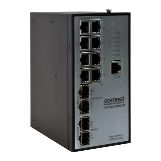
CNXE2GE2TX8MSPOE
INSTALLATION AND OPERATION MANUAL
CNXE2GE2TX8MSPOE
INDUSTRIALLY HARDENED
HIGH SPEED 12-PORT MANAGED POE ETHERNET SWITCH
8 × GE PSE + 2 × 2.5GE SFP + 2 × 10GE SFP+ PORTS
The ComNet CNXE2GE2TX8MSPOE is a twelve-port Managed Ethernet Switch
designed to reliably operate in harsh, environmentally challenging applications.
It features eight 10/100/1000BASE-TX ports supporting IEEE 802.2af/at PSE with a
total power budget of 240 watts with a maximum of thirty watts per port to provide
power in a PoE application. It also provides two 100/1G/2.5GBASE-X ports and two
1G/10GBASE-X SFP+ ports. The SFP ports are configurable by the use of compatible
ComNet SFP+ modules. These network-managed layer 2 switches are compatible
with any IEEE802.3 compliant Ethernet device.
Advertisement
Table of Contents

Related Manuals for Comnet CNXE2GE2TX8MSPOE


Summary of Contents for Comnet CNXE2GE2TX8MSPOE
- Page 1 HIGH SPEED 12-PORT MANAGED POE ETHERNET SWITCH 8 × GE PSE + 2 × 2.5GE SFP + 2 × 10GE SFP+ PORTS The ComNet CNXE2GE2TX8MSPOE is a twelve-port Managed Ethernet Switch This manual serves the following designed to reliably operate in harsh, environmentally challenging applications.
-
Page 2: Table Of Contents
INSTALLATION AND OPERATION MANUAL CNXE2GE2TX8MSPOE Contents Getting Started 1.1 About the CNXE2GE2TX8MSPOE 1.2 Software Features 1.3 Hardware Specifications Hardware Overview 2.1 Installing Switch on DIN-Rail 2.2 Wall Mounting Installation Hardware Overview 3.1 Front Panel 3.2 Front Panel LEDs 3.3 Top View Panel Hardware Installation 4.1 Wiring... - Page 3 INSTALLATION AND OPERATION MANUAL CNXE2GE2TX8MSPOE Management 6.1 Basic Settings 6.1.1 System Information 6.1.2 Auth Method 6.1.3 Users 6.1.4 IP Settings 6.1.5 IP Status 6.1.6 Daylight Saving Time 6.1.7 HTTPS 6.1.8 SSH 6.1.9 LLDP 6.1.10 NTP 6.1.11 Universal Plug and Play (UPnP) 6.1.12 ModbusTCP...
- Page 4 INSTALLATION AND OPERATION MANUAL CNXE2GE2TX8MSPOE 6.5.7 SNMP Access Configurations 6.5.8 RMON 6.6 Traffic Prioritization 6.6.1 Global Storm Policer Configuration 6.6.2 Port Classification 6.6.3 Port Tag Remaking 6.6.4 Port DSCP 6.6.5 Port Policing 6.6.6 Queue Policing 6.6.7 QoS Egress Port Scheduler and Shapers 6.6.8 Port Scheduler...
- Page 5 INSTALLATION AND OPERATION MANUAL CNXE2GE2TX8MSPOE 6.10 Monitor and Diag 6.10.1 MAC Table 6.10.2 Port Statistics 6.10.3 Port Monitoring 6.10.4 System Log Information 6.10.5 Cable Diagnostics 6.10.6 SFP Monitor 6.10.7 SFP Type 6.10.8 Ping 6.11 Power over Ethernet (PoE) 6.11.1 Configuration 6.11.2 Status...
-
Page 6: Getting Started
240 watts with a maximum of thirty watts per port to provide power in a PoE application. It also provides two 100/1G/2.5GBASE-X ports and two 1G/10GBASE-X SFP+ ports. The SFP ports are configurable by the use of compatible ComNet SFP+ modules. These network-managed layer 2 switches are compatible with any IEEE802.3 compliant Ethernet device. -
Page 7: Hardware Specifications
INSTALLATION AND OPERATION MANUAL CNXE2GE2TX8MSPOE 1.3 Hardware Specifications » Redundant 12~48VDC power inputs » 8 x 10/100/1000Base-T(X) ports, POE 30W » 2 x 1G/10GBase-X SFP+ sockets » 2 x 100/1G/2.5GBase-X SFP+ sockets » 1 x console port » Operating temperature: -20 to +60˚ C @ 2.5G/10G SFP or -40 to +75º C @ 1G »... -
Page 8: Hardware Overview
INSTALLATION AND OPERATION MANUAL CNXE2GE2TX8MSPOE Hardware Overview 2.1 Installing Switch on DIN-Rail Each switch has a DIN-Rail kit pre-installed on rear panel. Mount CNXE2GE2TX8MSPOE on DIN-Rail DIN-Rail Mount Kit TECH SUPPORT: 1.888.678.9427 INS_CNXE2GE2TX8MSPOE 11 Jan 2021 PAGE 8... -
Page 9: Wall Mounting Installation
INSTALLATION AND OPERATION MANUAL CNXE2GE2TX8MSPOE 2.2 Wall Mounting Installation Each switch includes an optional wall mount panel. Install wall mount panel CNXE2GE2TX8MSPOE Wall-Mount Kit TECH SUPPORT: 1.888.678.9427 INS_CNXE2GE2TX8MSPOE 11 Jan 2021 PAGE 9... -
Page 10: Hardware Overview
INSTALLATION AND OPERATION MANUAL CNXE2GE2TX8MSPOE Hardware Overview 3.1 Front Panel The following table describes the labeling on the front panel of the CNXE2GE2TX8MSPOE. Port Description DG SFP Port 2 x 100 / 1G / 2.5G TG SFP Port 2 x 1G / 10G... -
Page 11: Front Panel Leds
INSTALLATION AND OPERATION MANUAL CNXE2GE2TX8MSPOE 8. 10/100/1000Base-T(X) ports 9. LED for Ethernet ports link/act/speed status (right port indicator) (see table below) 10. SFP Port support 100 / 1G / 2.5G SFP+ Port support 1G / 10G 11. 10/100/1000Base-T(X) ports 12. LED for SFP Ports (see table below) 13. -
Page 12: Top View Panel
INSTALLATION AND OPERATION MANUAL CNXE2GE2TX8MSPOE 3.3 Top View Panel The bottom panel components of CNXE2GE2TX8MSPOE are as shown below: 1. Terminal block includes: PWR1, PWR2 (50-57V DC) 2. Ground wire TECH SUPPORT: 1.888.678.9427 INS_CNXE2GE2TX8MSPOE 11 Jan 2021 PAGE 12... -
Page 13: Hardware Installation
INSTALLATION AND OPERATION MANUAL CNXE2GE2TX8MSPOE Hardware Installation 4.1 Wiring ATTENTION 1. Be sure to disconnect the power cord before installing and/or wiring your switches. 2. Calculate the maximum possible current in each power wire and common wire. Observe all electrical codes dictating the maximum current allowable for each wire size. -
Page 14: Connection
INSTALLATION AND OPERATION MANUAL CNXE2GE2TX8MSPOE 4.2 Connection 4.2.1 Cables 1000/100BASE-TX/10BASE-T Pin Assignments The device has standard Ethernet ports. According to the link type, the switch uses CAT 3, 4, 5, or 5e UTP cables to connect to any other network devices (PCs, servers, switches, routers, or hubs). - Page 15 INSTALLATION AND OPERATION MANUAL CNXE2GE2TX8MSPOE The device supports auto MDI/MDI-X operation. You can use a cable to connect the switch to a PC. The table below shows the 10/100Base-T(X) MDI and MDI-X port pin outs. 10/100Base-T(X) MDI/MDI-X Pin Assignments: Pin Number...
-
Page 16: Sfp
INSTALLATION AND OPERATION MANUAL CNXE2GE2TX8MSPOE RS-232 console port wiring The device can be managed via console ports using the included RS-232 cable. You can connect the port to a PC via the RS-232 cable with a DB-9 female connector. The DB-9 female connector of the RS-232 cable should be connected the PC while the other end of the cable (RJ-45 connector) should be connected to the console port of the switch. -
Page 17: C-Ring
INSTALLATION AND OPERATION MANUAL CNXE2GE2TX8MSPOE 4.2.3 C-Ring C-Ring You can connect three or more switches to form a ring topology to gain network redundancy capabilities through the following steps. Connect each switch to form a daisy chain using an Ethernet cable. - Page 18 INSTALLATION AND OPERATION MANUAL CNXE2GE2TX8MSPOE Coupling Ring If you already have two Redundant-Ring topologies and would like to connect the rings, you can form them into a coupling ring. For example: » Select switches A and B from Ring 1 and switches C and D from Ring 2 »...
- Page 19 INSTALLATION AND OPERATION MANUAL CNXE2GE2TX8MSPOE Dual Homing Connect your ring topology to a RSTP network environment using dual homing. Choose switches A & B from the ring for connecting to the switches in the RSTP network (core switches). The connection of one of the switches (Switch A or B) will act as the primary path, while the other will act as the backup path that is activated when the primary path connection fails.
-
Page 20: Redundancy
INSTALLATION AND OPERATION MANUAL CNXE2GE2TX8MSPOE Redundancy Redundancy for minimized system downtime is one of the most important concerns for industrial networking devices. Our redundancy technologies feature faster recovery time than existing redundancy technologies widely used in commercial applications, such as STP, RSTP, and MSTP. -
Page 21: Configurations
INSTALLATION AND OPERATION MANUAL CNXE2GE2TX8MSPOE 5.1.2 Configurations Redundant-Ring supports two ring topologies: Coupling Ring, and Dual Homing. You can configure the settings in the interface below. Label Description C-Ring Check to enable C-Ring topology. Ring Master Only one ring master is allowed in a ring. However, if more than one switch are set to enable Ring Master, the switch with the lowest MAC address will be the active ring master and the others will be backup masters. -
Page 22: Erps
INSTALLATION AND OPERATION MANUAL CNXE2GE2TX8MSPOE 5.2 ERPS The ERPS instances are configured here. Please note that ERPS cannot be used in conjunction with Spanning Tree or Loop Protection on the same switch Note: For an example of how to configure an ERPS ring please refer to appendix A at the rear of this document. - Page 23 INSTALLATION AND OPERATION MANUAL CNXE2GE2TX8MSPOE Add New Click to add a new Protection group entry. Protection Group Refresh Click to refresh the page immediately. Apply Click to apply changes. Reset Click to undo any changes made locally and revert to previously saved values.
- Page 24 INSTALLATION AND OPERATION MANUAL CNXE2GE2TX8MSPOE Object Description Instance Configuration Configured Red: This ERPS is only created and has not yet been configured - is not active. Green: This ERPS is configured - is active. Guard Time Guard timeout value to be used to prevent ring nodes from receiving outdated R-APS messages.
- Page 25 INSTALLATION AND OPERATION MANUAL CNXE2GE2TX8MSPOE Object Description Port 0 OK: State of East port is ok SF: State of East port is Signal Fail Port 1 OK: State of West port is ok SF: State of West port is Signal Fail Transmit APS The transmitted APS according to State Transition Tables in G.8032.
-
Page 26: Vlan Membership Configuration
INSTALLATION AND OPERATION MANUAL CNXE2GE2TX8MSPOE VLAN Membership Configuration Object Description Delete To delete a VLAN entry, check this box. The entry will be deleted on all stack switch units during the next Save. VLAN ID Indicates the ID of this particular VLAN. -
Page 27: Mstp
INSTALLATION AND OPERATION MANUAL CNXE2GE2TX8MSPOE 5.3 MSTP 5.3.1 STP Configurations STP (Spanning Tree Protocol), and its advanced versions RSTP (Rapid Spanning Tree Protocol) and MSTP (Multiple Spanning Tree Protocol), are designed to prevent network loops and provide network redundancy. In large networks when two or more paths run to the same destination, broadcast packets may enter an infinite loop and cause congestion in the network. - Page 28 INSTALLATION AND OPERATION MANUAL CNXE2GE2TX8MSPOE Label Description Edge Port BPDU Control whether a port explicitly configured as Edge will transmit and receive Filtering BPDUs. Edge Port BPDU Control whether a port explicitly configured as Edge will disable itself upon Guard reception of a BPDU.
-
Page 29: Msti Mapping
INSTALLATION AND OPERATION MANUAL CNXE2GE2TX8MSPOE 5.3.2 MSTI Mapping The recovery time of STP and RSTP (seconds) may be unacceptable in some industrial applications. MSTP technology supports multiple spanning trees within a network by grouping and mapping multiple VLANs into different spanning-tree instances, known as MSTIs, to form individual MST regions. - Page 30 INSTALLATION AND OPERATION MANUAL CNXE2GE2TX8MSPOE Priority This page allows you to examine and change the configurations of current STP MSTI bridge instance priority. Label Description MSTI The bridge instance. CIST is the default instance, which is always active. Priority Indicates bridge priority. The lower the value, the higher the priority. The bridge priority, MSTI instance number, and the 6-byte MAC address of the switch forms a bridge identifier.
-
Page 31: Cist
INSTALLATION AND OPERATION MANUAL CNXE2GE2TX8MSPOE 5.3.3 CIST CIST is used by MSTP to communicate with other MSTP regions and with any RSTP and STP single-instance spanning trees in the network. Any boundary port connected to another region will automatically belong solely to CIST, even if it is assigned to an MSTI. All VLANs that are not members of particular MSTIs are members of the CIST. - Page 32 INSTALLATION AND OPERATION MANUAL CNXE2GE2TX8MSPOE Label Description Restricted TCN When enabled, the port will not propagate received topology change notifications and topology changes to other ports. If set, it will cause temporary disconnection after changes in an active spanning trees topology as a result of persistent incorrectly learned station location information.
-
Page 33: Msti Ports
INSTALLATION AND OPERATION MANUAL CNXE2GE2TX8MSPOE 5.3.4 MSTI Ports Configure STA attributes for interfaces in a specific MSTI, including path cost, and port priority. You may use a different priority or path cost for ports of the same media type to indicate the preferred path. -
Page 34: Bridge Status
INSTALLATION AND OPERATION MANUAL CNXE2GE2TX8MSPOE 5.3.5 Bridge Status Review STA information on the global bridge such as the switch and individual ports. Label Description MSTI Indicates the bridge instance. Bridge ID A unique identifier for this bridge, consisting of the bridge priority, and MAC address (where the address is taken from the switch system). - Page 35 INSTALLATION AND OPERATION MANUAL CNXE2GE2TX8MSPOE Label Description Port The port identifier. Port ID The port identifier used by the RSTP protocol, consisting of the priority and the logical port index of the bridge port. Role The role of a port is assigned based on whether it is part of the active topology connecting the bridge to the root bridge (i.e., root port), connecting a LAN...
-
Page 36: Port Status
INSTALLATION AND OPERATION MANUAL CNXE2GE2TX8MSPOE 5.3.6 Port Status Display the STP functional status of participating ports. Label Description Port The port identifier. CIST Role The role of a port is assigned based on whether it is part of the active topology connecting the bridge to the root bridge (i.e., root port), connecting a LAN... -
Page 37: Port Statistics
INSTALLATION AND OPERATION MANUAL CNXE2GE2TX8MSPOE 5.3.7 Port Statistics Label Description Port The port identifier. Transmitted/ MSTP: the number of MSTP Configuration BPDUs received/transmitted on a port. Received RSTP: the number of RSTP Configuration BPDUs received/transmitted on a port. RTP: the number of legacy STP Configuration BPDU’s received/transmitted on a port. -
Page 38: Management
INSTALLATION AND OPERATION MANUAL CNXE2GE2TX8MSPOE Management The switch can be controlled via a built-in web server which supports Internet Explorer (version 5.0 or newer) and other web browsers such as Chrome. Manage, configure and upgrade firmware remotely via a web browser. The Web management function not only reduces network bandwidth consumption, but also enhances access speed and provides a user-friendly viewing screen. - Page 39 INSTALLATION AND OPERATION MANUAL CNXE2GE2TX8MSPOE After logging in, you can see the information of the switch as below. On the left hand side of the management interface shows links to various settings. You can click on the links to access the configuration pages of different functions.
-
Page 40: Basic Settings
INSTALLATION AND OPERATION MANUAL CNXE2GE2TX8MSPOE 6.1 Basic Settings Configure the basic functions of the switch. 6.1.1 System Information Display general information of the switch. Label Description System Name Name assigned by administrator for the managed node. By convention, this is the node’s fully-qualified domain name. -
Page 41: Auth Method
INSTALLATION AND OPERATION MANUAL CNXE2GE2TX8MSPOE 6.1.2 Auth Method Authentication Method Configuration Configure how a user is authenticated when they log into the switch via one of the management client interfaces. Label Description Client The management client for which the configuration below applies. - Page 42 INSTALLATION AND OPERATION MANUAL CNXE2GE2TX8MSPOE Command Authorization Method Configuration Limit the CLI commands available to a user. Label Description Client The management client for which the configuration below applies. Methods Method can be set to one of the following values: »...
- Page 43 INSTALLATION AND OPERATION MANUAL CNXE2GE2TX8MSPOE Accounting Method Configuration Configure command and exec (login) accounting. Label Description Client The management client for which the configuration below applies. Methods Method can be set to one of the following values: » no: Accounting is disabled.
-
Page 44: Users
INSTALLATION AND OPERATION MANUAL CNXE2GE2TX8MSPOE 6.1.3 Users Configuration An overview of the current users. Currently the only way to login as another user on the web server is to close and reopen the browser. Label Description User Name A string identifying the user name that this entry should belong to. The allowed string length is 1 to 31. - Page 45 INSTALLATION AND OPERATION MANUAL CNXE2GE2TX8MSPOE Privilege Levels An overview of the privilege levels. Label Description Group Name The name identifying the privilege group. In most cases, a privilege level group consists of a single module (e.g. LACP, RSTP or QoS), but a few of them contains more than one.
-
Page 46: Ip Settings
INSTALLATION AND OPERATION MANUAL CNXE2GE2TX8MSPOE 6.1.4 IP Settings Configure IP information for the switch. You can configure the settings of the device operating in host or router mode. IP Configuration An overview of the privilege levels. Label Description VLAN The VLAN associated with the IP interface. Only ports in this VLAN will be able to access the IP interface. - Page 47 INSTALLATION AND OPERATION MANUAL CNXE2GE2TX8MSPOE Label Description IPv6 Address The IPv6 address of the interface. An IPv6 address is in 128-bit records represented as eight fields of up to four hexadecimal digits with a colon separating each field (:). For example, fe80::215:c5ff:fe03:4dc7. The symbol :: is a special syntax that can be used as a shorthand way of representing multiple 16-bit groups of contiguous zeros;...
-
Page 48: Ip Status
INSTALLATION AND OPERATION MANUAL CNXE2GE2TX8MSPOE 6.1.5 IP Status The status of the IP protocol layer. The status is defined by the IP interfaces, the IP routes and the neighbor cache (ARP cache) status. Label Description IP Interface Interface The name of the interface. -
Page 49: Daylight Saving Time
INSTALLATION AND OPERATION MANUAL CNXE2GE2TX8MSPOE 6.1.6 Daylight Saving Time Label Description Time Zone Configuration Time Zone: Set the switch location time zone. The following table lists the different location time zone for your reference. Acronym: User can set the acronym of the time zone. This is a User configurable acronym to identify the time zone. - Page 50 INSTALLATION AND OPERATION MANUAL CNXE2GE2TX8MSPOE Local Time Zone Conversion from UTC Time at 12:00 UTC November Time Zone - 1 hour 11 am Oscar Time Zone -2 hours 10 am ADT - Atlantic Daylight -3 hours 9 am AST - Atlantic Standard...
-
Page 51: Https
INSTALLATION AND OPERATION MANUAL CNXE2GE2TX8MSPOE 6.1.7 HTTPS Configure the HTTPS mode on this page. Label Description Mode Enables or disables HTTPS mode. Automatic Redirect Enables or disables automatic redirect function. It is only significant when HTTPS mode is enabled. When the redirect mode is enabled, the HTTP connection will be redirected to HTTPS connection automatically. -
Page 52: Ssh
INSTALLATION AND OPERATION MANUAL CNXE2GE2TX8MSPOE 6.1.8 SSH Configure the SSH mode on this page. Label Description Mode Enable or disable SSH. Save Click to save changes Reset Click to undo any changes made locally and revert to previously saved values. -
Page 53: Lldp
INSTALLATION AND OPERATION MANUAL CNXE2GE2TX8MSPOE 6.1.9 LLDP LLDP Configurations Review and configure current LLDP port settings. Label Description Tx Interval The switch periodically transmits LLDP frames to its neighbors to update the network discovery information. The interval between each LLDP frame is determined by the Tx Interval value which must be between 5 - 32768 seconds. - Page 54 INSTALLATION AND OPERATION MANUAL CNXE2GE2TX8MSPOE Label Description Interface The switch interface name of the logical LLDP interface. Mode Select a LLDP mode from the drop down list. Rx only: The switch will not send out LLDP information, but LLDP information from neighbor units is analyzed.
- Page 55 INSTALLATION AND OPERATION MANUAL CNXE2GE2TX8MSPOE LLDP Neighbor Information A status overview for all LLDP neighbors. The following table contains information for each port on which an LLDP neighbor is detected. Label Description Local Port The port that you use to transmits and receives LLDP frames.
- Page 56 INSTALLATION AND OPERATION MANUAL CNXE2GE2TX8MSPOE Port Statistics An overview of all LLDP traffic. Two types of counters are shown. Global counters will apply settings to the whole switch stack, while local counters will apply settings to specified switches. Global Counters...
- Page 57 INSTALLATION AND OPERATION MANUAL CNXE2GE2TX8MSPOE Local Counters Label Description Local Port The port that receives or transmits LLDP frames Tx Frames The number of LLDP frames transmitted on the port Rx Frames The number of LLDP frames received on the port...
-
Page 58: Ntp
INSTALLATION AND OPERATION MANUAL CNXE2GE2TX8MSPOE 6.1.10 NTP Specify the Network Time Protocol (NTP) servers to query for the current time to maintain an accurate time on the switch, ensuring the system log records meaningful dates and times for event entries. With NTP, the switch can set its internal clock periodically according to an NTP time server. -
Page 59: Universal Plug And Play (Upnp)
INSTALLATION AND OPERATION MANUAL CNXE2GE2TX8MSPOE 6.1.11 Universal Plug and Play (UPnP) UPnP allows devices to connect seamlessly and simplifies the implementation of networks in the home (data sharing, communications, and entertainment) and in corporate environments for installation of computer components. -
Page 60: Modbustcp
INSTALLATION AND OPERATION MANUAL CNXE2GE2TX8MSPOE 6.1.12 ModbusTCP For more about Modbus please reference http://www.modbus.org/ The following table describes the labels in this screen. Label Description Mode Enable or Disalble Modbus TCP function 6.1.13 Ethernet/IP EtherNet/IP adapts the Common Industrial Protocol to standard Ethernet. EtherNet/IP is one of the leading industrial protocols in the United States and is widely used in a range of industries including factory, hybrid, and process. -
Page 61: Backup/Restore Configurations
INSTALLATION AND OPERATION MANUAL CNXE2GE2TX8MSPOE 6.1.14 Backup/Restore Configurations Save, view, or load switch configurations. TECH SUPPORT: 1.888.678.9427 INS_CNXE2GE2TX8MSPOE 11 Jan 2021 PAGE 61... -
Page 62: Firmware Update
INSTALLATION AND OPERATION MANUAL CNXE2GE2TX8MSPOE 6.1.15 Firmware Update Update the firmware of the switch. TECH SUPPORT: 1.888.678.9427 INS_CNXE2GE2TX8MSPOE 11 Jan 2021 PAGE 62... -
Page 63: Dhcp
INSTALLATION AND OPERATION MANUAL CNXE2GE2TX8MSPOE 6.2 DHCP 6.2.1 DHCP Server Configure global mode and VLAN mode to enable/disable DHCP server per system and per VLAN. Mode Label Description Global Mode Mode Configure the operation mode per system. Possible modes are: Enabled: Enable DHCP server per system. - Page 64 INSTALLATION AND OPERATION MANUAL CNXE2GE2TX8MSPOE Label Description VLAN Range Indicate the VLAN range in which DHCP server is enabled or disabled. The first VLAN ID must be smaller than or equal to the second VLAN ID. BUT, if the VLAN range contains only 1 VLAN ID, then you can just input it into either one of the first and second VLAN ID or both.
- Page 65 INSTALLATION AND OPERATION MANUAL CNXE2GE2TX8MSPOE Pool Manage DHCP pools. According to the DHCP pool, DHCP server will allocate IP address and deliver configuration parameters to DHCP client. Label Description Name Configure the pool name that accepts all printable characters, except white space. If you want to configure the detail settings, you can click the pool name to go into the configuration page.
- Page 66 INSTALLATION AND OPERATION MANUAL CNXE2GE2TX8MSPOE Statistics Review the database counters and the number of DHCP messages sent and received by DHCP server. Label Description Database Counters Pool Number of pools. Excluded IP Address Number of excluded IP address ranges. Declined IP Address Number of declined IP addresses.
- Page 67 INSTALLATION AND OPERATION MANUAL CNXE2GE2TX8MSPOE Binding Review bindings generated for DHCP clients. Label Description IP address allocated to DHCP client. Type Type of binding. Possible types are Automatic, Manual, Expired. State State of binding. Possible states are Committed, Allocated, Expired.
-
Page 68: Dhcp Relay
INSTALLATION AND OPERATION MANUAL CNXE2GE2TX8MSPOE 6.2.2 DHCP Relay DHCP relay is used to forward and transfer DHCP messages between the clients and the server when they are not in the same subnet domain. You can configure the function in this page. - Page 69 INSTALLATION AND OPERATION MANUAL CNXE2GE2TX8MSPOE The relay statistics shows the information of relayed packets of the switch. Label Description Transmit to Sever The number of packets relayed from the client to the server Transmit Error The number of packets with errors when being sent to clients...
-
Page 70: Dhcp Snooping
INSTALLATION AND OPERATION MANUAL CNXE2GE2TX8MSPOE 6.2.3 DHCP Snooping Snooping Configure DHCP Snooping on this page. Label Description Snooping Mode Indicates the DHCP snooping mode operation. Possible modes are: Enabled: Enable DHCP snooping mode operation. When DHCP snooping mode operation is enabled, the DHCP request messages will be forwarded to trusted ports and only allow reply packets from trusted ports. - Page 71 INSTALLATION AND OPERATION MANUAL CNXE2GE2TX8MSPOE Snooping Table This page displays the dynamic IP assigned information after DHCP Snooping mode is disabled. All DHCP clients obtained the dynamic IP address from the DHCP server will be listed in this table except for local VLAN interface IP addresses. Entries in the Dynamic DHCP snooping Table are shown on this page.
- Page 72 INSTALLATION AND OPERATION MANUAL CNXE2GE2TX8MSPOE Detailed Statistics This page provides statistics for DHCP snooping. Notice that the normal forward per-port TX statistics isn't increased if the incoming DHCP packet is done by L3 forwarding mechanism. And clear the statistics on specific port may not take effect on global statistics since it gathers the different layer overview.
-
Page 73: Port Setting
INSTALLATION AND OPERATION MANUAL CNXE2GE2TX8MSPOE 6.3 Port Setting Manage individual ports of the switch, including traffic, power, and trunks. 6.3.1 Port Control This page shows current port configurations. Ports can also be configured here. Label Description Port This is the logical port number for this row. - Page 74 INSTALLATION AND OPERATION MANUAL CNXE2GE2TX8MSPOE Label Description Advertise Speed When Speed is set as auto i.e auto negotiation, the port will only advertise the specified speeds (10M 100M 1G) to the link partner. By default port will advertise all the supported speeds if speed is set as Auto.
-
Page 75: Port Trunk
INSTALLATION AND OPERATION MANUAL CNXE2GE2TX8MSPOE 6.3.2 Port Trunk A port trunk is a group of ports that have been grouped together to function as one logical path. This method provides an economical way for you to increase the bandwidth between the switch and another networking device. - Page 76 INSTALLATION AND OPERATION MANUAL CNXE2GE2TX8MSPOE Label Description Group ID Indicates the ID of each aggregation group. Normal means no aggregation. Only one group ID is valid per port. Port Members Lists each switch port for each group ID. Select a radio button to include a port in an aggregation, or clear the radio button to remove the port from the aggregation.
- Page 77 INSTALLATION AND OPERATION MANUAL CNXE2GE2TX8MSPOE LACP LACP (Link Aggregation Control Protocol) trunks are similar to static port trunks, but they are more flexible because LACP is compliant with the IEEE 802.3ad standard. Hence, it is interoperable with equipment from other vendors that also comply with the standard. This page allows you to...
- Page 78 INSTALLATION AND OPERATION MANUAL CNXE2GE2TX8MSPOE LACP System Status This page provides a status overview for all LACP instances. Label Description Aggr ID The aggregation ID is associated with the aggregation instance. For LLAG, the ID is shown as ‘isid:aggr-id’ and for GLAGs as ‘aggr-id’...
- Page 79 INSTALLATION AND OPERATION MANUAL CNXE2GE2TX8MSPOE LACP Port Status This page provides an overview of the LACP status for all ports. Label Description Port Switch port number LACP Yes means LACP is enabled and the port link is up. No means LACP is not enabled or the port link is down.
- Page 80 INSTALLATION AND OPERATION MANUAL CNXE2GE2TX8MSPOE LACP Port Statistics This page provides an overview of the LACP statistics for all ports. Label Description Port Switch port number LACP Transmitted The number of LACP frames sent from each port LACP Received The number of LACP frames received at each port Discarded The number of unknown or illegal LACP frames discarded at each port.
-
Page 81: Loop Protection
INSTALLATION AND OPERATION MANUAL CNXE2GE2TX8MSPOE 6.3.3 Loop Protection This feature prevents loop attack. When receiving loop packets, the port will be disabled automatically, preventing the loop attack from affecting other network devices. Configuration Label Description Enable Loop Protection Activate loop protection functions (as a whole) Transmission Time The interval between each loop protection PDU sent on each port. -
Page 82: Vlan Membership
INSTALLATION AND OPERATION MANUAL CNXE2GE2TX8MSPOE 6.4 VLAN 6.4.1 VLAN Membership A VLAN is a group of end devices with a common set of requirements, independent of physical location. With the same attributes as a physical LAN, VLANs enable you to group end devices even if they are not located physically on the same LAN segment. - Page 83 INSTALLATION AND OPERATION MANUAL CNXE2GE2TX8MSPOE Port VLAN Configuration Label Description Port This is the logical port number of this row. Mode The port mode (default is Access) determines the fundamental behavior of the port in question. A port can be in one of three modes as described below.
- Page 84 INSTALLATION AND OPERATION MANUAL CNXE2GE2TX8MSPOE Label Description Port VLAN Determines the port’s VLAN ID (a.k.a. PVID). Allowed VLANs are in the range 1 through 4095, default being 1. On ingress, frames get classified to the Port VLAN if the port is configured as VLAN unaware, the frame is untagged, or VLAN awareness is enabled on the port, but the frame is priority tagged (VLAN ID = 0).
- Page 85 INSTALLATION AND OPERATION MANUAL CNXE2GE2TX8MSPOE Label Description Ingress Hybrid ports allow for changing the type of frames that are accepted on ingress. Acceptance Tagged and Untagged Both tagged and untagged frames are accepted. See Port Type for a description of when a frame is considered tagged.
-
Page 86: Membership Status
INSTALLATION AND OPERATION MANUAL CNXE2GE2TX8MSPOE 6.4.2 Membership Status This page provides an overview of membership status of VLAN users. Label Description VLAN User Various internal software modules may use VLAN services to configure VLAN memberships on the fly. The drop-down list on the right allows for selecting between showing VLAN memberships as configured by an administrator (Admin) or as configured by one of these internal software modules. -
Page 87: Port Status
INSTALLATION AND OPERATION MANUAL CNXE2GE2TX8MSPOE 6.4.3 Port Status This page provides VLAN Port Status Label Description VLAN User Various internal software modules may use VLAN services to configure VLAN port configuration on the fly. The drop-down list on the right allows for selecting between showing VLAN memberships as configured by an administrator (Admin) or as configured by one of these internal software modules. -
Page 88: Private Vlan
INSTALLATION AND OPERATION MANUAL CNXE2GE2TX8MSPOE Label Description Conflicts Two users may have conflicting requirements to a port’s configuration. For instance, one user may require all frames to be tagged on egress while another requires all frames to be untagged on egress. - Page 89 INSTALLATION AND OPERATION MANUAL CNXE2GE2TX8MSPOE Label Description Port Members A row of check boxes for each port is displayed for each private VLAN ID. You can check the box to include a port in a private VLAN. To remove or exclude the port from the private VLAN, make sure the box is unchecked.
-
Page 90: Gvrp
INSTALLATION AND OPERATION MANUAL CNXE2GE2TX8MSPOE 6.4.5 GVRP GVRP is an acronym for GARP VLAN Registration Protocol. It is a protocol for dynamicaly registering VLANs on ports, and is specified in IEEE 802.1Q-2005, clause 11. GVRP is an example of the use of GARP, hence the G in GVRP. - Page 91 INSTALLATION AND OPERATION MANUAL CNXE2GE2TX8MSPOE Port Config Enable or disable a port for GVRP operation. This configuration can be performed either before or after GVRP is configured globally - the protocol operation will be the same. Label Description Port The logical port that is to be configured.
-
Page 92: Snmp
INSTALLATION AND OPERATION MANUAL CNXE2GE2TX8MSPOE 6.5 SNMP 6.5.1 SNMP System Configurations Label Description Mode Indicates existing SNMP mode. Possible modes include: Enabled: enable SNMP mode Disabled: disable SNMP mode Version Indicates the supported SNMP version. Possible versions include: SNMP v1: supports SNMP version 1. -
Page 93: Trap
INSTALLATION AND OPERATION MANUAL CNXE2GE2TX8MSPOE 6.5.2 Trap SNMP Trap Detailed Configuration Label Description Trap Config Name Indicates which trap Configuration’s name for configuring. The allowed string length is 1 to 32, and the allowed content is ASCII characters from 33 to 126. - Page 94 INSTALLATION AND OPERATION MANUAL CNXE2GE2TX8MSPOE Label Description Trap Destination Indicates the SNMP trap destination address. It allow a valid IP address in dotted Address decimal notation (‘x.y.z.w’). And it also allows a valid hostname. A valid hostname is a string drawn from the alphabet (A-Za-z), digits (0-9), dot (.), dash (-).
- Page 95 INSTALLATION AND OPERATION MANUAL CNXE2GE2TX8MSPOE SNMP Trap Event Label Description System Enable/disable that the Interface group’s traps. Possible traps are: Warm Start: Enable/disable Warm Start trap. Cold Start: Enable/disable Cold Start trap. Interface Indicates that the Interface group’s traps. Possible traps are: Indicates that the SNMP entity is permitted to generate authentication failure traps.
-
Page 96: Snmp Community Configurations
INSTALLATION AND OPERATION MANUAL CNXE2GE2TX8MSPOE 6.5.3 SNMP Community Configurations Configure the SNMPv3 community table. The entry index key is Community. Label Description Delete Check to delete the entry. It will be deleted during the next save. Community Indicates the community access string to permit access to SNMPv3 agent. The allowed string length is 1 to 32, and only ASCII characters from 33 to 126 are allowed. -
Page 97: Snmp User Configurations
INSTALLATION AND OPERATION MANUAL CNXE2GE2TX8MSPOE 6.5.4 SNMP User Configurations Configure SNMPv3 user table. The entry index keys are Engine ID and User Name. Label Description Delete Check to delete the entry. It will be deleted during the next save. Engine ID An octet string identifying the engine ID that this entry should belong to. -
Page 98: Snmp Group Configurations
INSTALLATION AND OPERATION MANUAL CNXE2GE2TX8MSPOE Label Description Privacy Protocol Indicates the privacy protocol that this entry should belong to. Possible privacy protocols include: None: no privacy protocol DES: an optional flag to indicate that this user is using DES authentication... -
Page 99: Snmp View Configurations
INSTALLATION AND OPERATION MANUAL CNXE2GE2TX8MSPOE 6.5.6 SNMP View Configurations Configure SNMPv3 view table. The entry index keys are View Name and OID Subtree. Label Description Delete Check to delete the entry. It will be deleted during the next save. View Name A string identifying the view name that this entry should belong to. -
Page 100: Snmp Access Configurations
INSTALLATION AND OPERATION MANUAL CNXE2GE2TX8MSPOE 6.5.7 SNMP Access Configurations Configure SNMPv3 access table. The entry index keys are Group Name, Security Model, and Security Level. Label Description Delete Check to delete the entry. It will be deleted during the next save. -
Page 101: Rmon
INSTALLATION AND OPERATION MANUAL CNXE2GE2TX8MSPOE 6.5.8 RMON Statistics Configuration Label Description Delete Check to delete the entry. It will be deleted during the next save. Indicates the index of the entry. The range is from 1 to 65535. Data Source Indicates the port ID which wants to be monitored. - Page 102 INSTALLATION AND OPERATION MANUAL CNXE2GE2TX8MSPOE Alarm Configuration Label Description Delete Check to delete the entry. It will be deleted during the next save. Indicates the index of the entry. The range is from 1 to 65535. Interval Indicates the interval in seconds for sampling and comparing the rising and falling threshold.
- Page 103 INSTALLATION AND OPERATION MANUAL CNXE2GE2TX8MSPOE Label Description Rising Threshold Rising threshold value (-2147483648-2147483647). Rising Index Rising event index (1-65535). Falling Threshold Falling threshold value (-2147483648-2147483647) Falling Index Falling event index (1-65535). Event Configuration Label Description Delete Check to delete the entry. It will be deleted during the next save.
- Page 104 INSTALLATION AND OPERATION MANUAL CNXE2GE2TX8MSPOE Statistics Stauts Label Description Indicates the index of Statistics entry. Data Source The port ID which wants to be monitored. Octets The total number of events in which packets were dropped by the probe due to lack of resources.
- Page 105 INSTALLATION AND OPERATION MANUAL CNXE2GE2TX8MSPOE History Status Label Description History Index Indicates the index of History control entry. Sample Index Indicates the index of the data entry associated with the control entry. Sample Start The value of sysUpTime at the start of the interval over which this sample was measured.
- Page 106 INSTALLATION AND OPERATION MANUAL CNXE2GE2TX8MSPOE Alarm Status Label Description Indicates the index of Alarm control entry. Interval Indicates the interval in seconds for sampling and comparing the rising and falling threshold. Variable Indicates the particular variable to be sampled Sample Type The method of sampling the selected variable and calculating the value to be compared against the thresholds.
-
Page 107: Traffic Prioritization
INSTALLATION AND OPERATION MANUAL CNXE2GE2TX8MSPOE 6.6 Traffic Prioritization 6.6.1 Global Storm Policer Configuration There is a unicast storm rate control, multicast storm rate control, and a broadcast storm rate control. These only affect flooded frames, i.e. frames with a (VLAN ID, DMAC) pair not present on the MAC Address table. -
Page 108: Port Classification
INSTALLATION AND OPERATION MANUAL CNXE2GE2TX8MSPOE 6.6.2 Port Classification QoS is an acronym for Quality of Service. It is a method to achieve efficient bandwidth utilization between individual applications or protocols. Label Description Port The port number for which the configuration below applies... -
Page 109: Port Tag Remaking
INSTALLATION AND OPERATION MANUAL CNXE2GE2TX8MSPOE Label Description Controls the default DEI value All frames are classified to a DEI value. If the port is VLAN aware and the frame is tagged, then the frame is classified to the DEI value in the tag. Otherwise the frame is classified to the default DEI value. -
Page 110: Port Dscp
INSTALLATION AND OPERATION MANUAL CNXE2GE2TX8MSPOE 6.6.4 Port DSCP Configure basic QoS Port DSCP settings for all switch ports. Label Description Port Shows the list of ports for which you can configure DSCP Ingress and Egress settings. Ingress In Ingress settings you can change ingress translation and classification settings for individual ports. -
Page 111: Port Policing
INSTALLATION AND OPERATION MANUAL CNXE2GE2TX8MSPOE 6.6.5 Port Policing Configure Policer settings for all switch ports. Label Description Port The port number for which the configuration below applies Enable Check to enable the policer for individual switch ports Rate Configures the rate of each policer. The default value is 500. This value is restricted to 100 to 1000000 when the Unit is kbps or fps, and is restricted to 1 to 3300 when the Unit is Mbps or kfps. -
Page 112: Queue Policing
INSTALLATION AND OPERATION MANUAL CNXE2GE2TX8MSPOE 6.6.6 Queue Policing Configure Queue Policer settings for all switch ports. Label Description Port The port number for which the configuration below applies. Enable(E) Check to enable queue policer for individual switch ports Rate Configures the rate of each queue policer. The default value is 500. This value is restricted to 100 to 1000000 when the Unit is kbps, and is restricted to 1 to 3300 when the Unit is Mbps. -
Page 113: Qos Egress Port Scheduler And Shapers
INSTALLATION AND OPERATION MANUAL CNXE2GE2TX8MSPOE 6.6.7 QoS Egress Port Scheduler and Shapers Configure Scheduler and Shapers for a specific port. Strict Priority Label Description Scheduler Mode Controls whether the scheduler mode is Strict Priority or Weighted on this switch port... - Page 114 INSTALLATION AND OPERATION MANUAL CNXE2GE2TX8MSPOE Weighted Label Description Scheduler Mode Controls whether the scheduler mode is Strict Priority or Weighted on this switch port Queue Shaper Check to enable queue shaper for individual switch ports Enable Queue Shaper Rate Configures the rate of each queue shaper. The default value is 500. This value is restricted to 100 to 1000000 when the Unit is kbps, and it is restricted to 1 to 3300 when the Unit is Mbps.
-
Page 115: Port Scheduler
INSTALLATION AND OPERATION MANUAL CNXE2GE2TX8MSPOE Label Description Port Shaper Unit Configures the unit of measurement for each port shaper rate as kbps or Mbps. The default value is kbps. 6.6.8 Port Scheduler This page provides an overview of QoS Egress Port Schedulers for all switch ports. - Page 116 INSTALLATION AND OPERATION MANUAL CNXE2GE2TX8MSPOE TECH SUPPORT: 1.888.678.9427 INS_CNXE2GE2TX8MSPOE 11 Jan 2021 PAGE 116...
-
Page 117: Dscp-Based Qos
INSTALLATION AND OPERATION MANUAL CNXE2GE2TX8MSPOE 6.6.10 DSCP-Based QoS Configure basic QoS DSCP-based QoS Ingress Classification settings for all switches. Label Description DSCP Maximum number of supported DSCP values is 64 Trust Check to trust a specific DSCP value. Only frames with trusted DSCP values are mapped to a specific QoS class and drop precedence level. -
Page 118: Dscp Translation
INSTALLATION AND OPERATION MANUAL CNXE2GE2TX8MSPOE 6.6.11 DSCP Translation Configure basic QoS DSCP translation settings for all switches. DSCP translation can be done in Ingress or Egress. Label Description DSCP Maximum number of supported DSCP values is 64 and valid DSCP value ranges from 0 to 63. -
Page 119: Dscp Classification
INSTALLATION AND OPERATION MANUAL CNXE2GE2TX8MSPOE 6.6.12 DSCP Classification Configure the mapping of QoS class and Drop Precedence Level to DSCP value. Label Description QoS Class Actual QoS class Actual Drop Precedence Level DSCP Select the classified DSCP value (0-63) TECH SUPPORT: 1.888.678.9427... -
Page 120: Qos Control List
INSTALLATION AND OPERATION MANUAL CNXE2GE2TX8MSPOE 6.6.13 QoS Control List Edit or insert a single QoS control entry at a time. A QCE consists of several parameters. These parameters vary with the frame type you select. Label Description Port Members Check to include the port in the QCL entry. By default, all ports are included. - Page 121 INSTALLATION AND OPERATION MANUAL CNXE2GE2TX8MSPOE Label Description Ethernet Valid Ethernet values can range from 0x600 to 0xFFFF or Any’ but excluding 0x800(IPv4) and 0x86DD(IPv6). The default value is Any. SSAP Address: valid SSAP (Source Service Access Point) values can range from 0x00 to 0xFF or Any.
-
Page 122: Qos Counters
INSTALLATION AND OPERATION MANUAL CNXE2GE2TX8MSPOE 6.6.14 QoS Counters This page provides the statistics of individual queues for all switch ports. Label Description Port The switch port number to which the following settings will be applied. There are 8 QoS queues per port. Q0 is the lowest priority... -
Page 123: Qcl Status
INSTALLATION AND OPERATION MANUAL CNXE2GE2TX8MSPOE 6.6.15 QCL Status This page shows the QCL status by different QCL users. Each row describes the QCE that is defined. It is a conflict if a specific QCE is not applied to the hardware due to hardware limitations. -
Page 124: Wred
INSTALLATION AND OPERATION MANUAL CNXE2GE2TX8MSPOE 6.6.16 WRED Configure the Random Early Detection (RED) settings. Through different RED configuration for the queues (QoS classes) it is possible to obtain Weighted Random Early Detection (WRED) operation between queues. The settings are global for all ports in the switch. - Page 125 INSTALLATION AND OPERATION MANUAL CNXE2GE2TX8MSPOE RED Drop Probability Function Min is the fill level where the queue randomly start dropping frames marked with Drop Precedence Level > 0 (yellow frames). If Max Unit is 'Drop Probability' (the green line), Max controls the drop probability when the fill level is just below 100%.
-
Page 126: Multicast
INSTALLATION AND OPERATION MANUAL CNXE2GE2TX8MSPOE 6.7 Multicast 6.7.1 IGMP Snooping This page provides IGMP Snooping related configurations. Label Description Snooping Enabled Check to enable global IGMP snooping Unregistered Enable unregistered IPMCv4 traffic flooding. IPMCv4Flooding The flooding control takes effect only when IGMP Snooping is enabled. When IGMP... - Page 127 INSTALLATION AND OPERATION MANUAL CNXE2GE2TX8MSPOE VLAN Configurations of IGMP Snooping Each page shows up to 99 entries from the VLAN table, with a default value of 20, selected by the Entries Per Page input field. When first visited, the web page will show the first 20 entries from the beginning of the VLAN Table.
- Page 128 INSTALLATION AND OPERATION MANUAL CNXE2GE2TX8MSPOE Label Description Query Interval. The Query Interval is the interval between General Queries sent by the Querier. The allowed range is 1 to 31744 seconds, default query interval is 125 seconds. Query Response Interval. The Maximum Response Delay used to calculate the Maximum Response Code inserted into the periodic General Queries.
- Page 129 INSTALLATION AND OPERATION MANUAL CNXE2GE2TX8MSPOE IGMP Snooping Status This page provides IGMP snooping status. Label Description VLAN ID The VLAN ID of the entry Querier Version Active Querier version Host Version Active Host version Querier Status Shows the Querier status as ACTIVE or IDLE...
- Page 130 INSTALLATION AND OPERATION MANUAL CNXE2GE2TX8MSPOE Groups Information of IGMP Snooping Entries in the IGMP Group Table are shown on this page. The IGMP Group Table is sorted first by VLAN ID, and then by group. Label Description VLAN ID The VLAN ID of the group...
- Page 131 INSTALLATION AND OPERATION MANUAL CNXE2GE2TX8MSPOE IPv4 SFM Information Entries in the IGMP SFM Information Table are shown on this page. The IGMP SFM (Source-Filtered Multicast) Information Table also contains the SSM (Source-Specific Multicast) information. This table is sorted first by VLAN ID, then by group, and then by Port. Different source addresses belong to the same group are treated as single entry.
- Page 132 INSTALLATION AND OPERATION MANUAL CNXE2GE2TX8MSPOE Port Group Filtering Label Description Port The logical port for the settings. Filtering Profile Select the IPMC Profile as the filtering condition for the specific port. Summary about the designated profile will be shown by clicking the view button.
-
Page 133: Security
INSTALLATION AND OPERATION MANUAL CNXE2GE2TX8MSPOE 6.8 Security 6.8.1 Device Binding This page provides device binding configurations. Device binding is a powerful way to monitor devices and network security. Label Description Mode Indicates the device binding operation for each port. Possible modes are:... -
Page 134: Advanced Configurations
INSTALLATION AND OPERATION MANUAL CNXE2GE2TX8MSPOE 6.8.2 Advanced Configurations Alias IP Address This page provides Alias IP Address configuration. Some devices might have more than one IP addresses. You could specify the other IP address here. Label Description Alias IP Address Specifies alias IP address. - Page 135 INSTALLATION AND OPERATION MANUAL CNXE2GE2TX8MSPOE DDoS Prevention This page provides DDOS Prevention configurations. The switch can monitor ingress packets, and perform actions when DDOS attack occurred on this port. You can configure the setting to achieve maximum protection. Label Description...
- Page 136 INSTALLATION AND OPERATION MANUAL CNXE2GE2TX8MSPOE Label Description Status Indicates the DDOS prevention status. Possible statuses are: ---: disables DDOS prevention Analyzing: analyzes packet throughput for initialization Running: analysis completes and ready for next move Attacked: DDOS attacks occur Device Description This page allows you to configure device description settings.
- Page 137 INSTALLATION AND OPERATION MANUAL CNXE2GE2TX8MSPOE Mode Enables or disables stream monitoring of the port Action Indicates the action to take when the stream gets low. Possible actions are: ---: no action Log it: simply logs the event TECH SUPPORT: 1.888.678.9427...
-
Page 138: Access Management
INSTALLATION AND OPERATION MANUAL CNXE2GE2TX8MSPOE 6.8.2 Access Management Configuration You can configure access management table on this page. If the application's type match any one of the access management entries, it will allow access to the switch. Label Description Delete Check to delete the entry. -
Page 139: Ip Source Guard
INSTALLATION AND OPERATION MANUAL CNXE2GE2TX8MSPOE 6.8.3 IP Source Guard IP source guard can prevent traffic attacks if a host tries to use the IP address of its neighbor. You can enable IP source guard when DHCP snooping is enabled on an untrusted interface. - Page 140 INSTALLATION AND OPERATION MANUAL CNXE2GE2TX8MSPOE Static Table Label Description Delete Check to delete the entry. It will be deleted during the next save. Port The logical port for the settings. VLAN ID The vlan id for the settings. IP Address Allowed Source IP address.
-
Page 141: Acl
INSTALLATION AND OPERATION MANUAL CNXE2GE2TX8MSPOE 6.8.4 ACL Ports Configure the ACL parameters (ACE) of each switch port. These parameters will affect frames received on a port unless the frame matches a specific ACE. Label Description Port The switch port number to which the following settings will be applied Policy ID Select to apply a policy to the port. - Page 142 INSTALLATION AND OPERATION MANUAL CNXE2GE2TX8MSPOE Rate Limiters Configure the rate limiter for the ACL of the switch. Label Description Rate Limiter ID The rate limiter ID for the settings contained in the same row. Rate The rate unit is packet per second (pps), which can be configured as 1, 2, 4, 8, 16, 32, 64, 128, 256, 512, 1K, 2K, 4K, 8K, 16K, 32K, 64K, 128K, 256K, 512K, or 1024K.
- Page 143 INSTALLATION AND OPERATION MANUAL CNXE2GE2TX8MSPOE ACL Control List Configure ACE (Access Control Entry). An ACE consists of several parameters. These parameters vary with the frame type you have selected. First select the ingress port for the ACE, and then the frame type. Different parameter options are displayed according to the frame type you have selected.
- Page 144 INSTALLATION AND OPERATION MANUAL CNXE2GE2TX8MSPOE Label Description SMAC Filter (Only displayed when the frame type is Ethernet Type or ARP.) Specifies the source MAC filter for the ACE. Any: no SMAC filter is specified (SMAC filter status is “don't-care”). Specific: if you want to filter a specific source MAC address with the ACE, choose this value.
- Page 145 INSTALLATION AND OPERATION MANUAL CNXE2GE2TX8MSPOE Label Description VLAN ID Filter Specifies the VLAN ID filter for the ACE Any: no VLAN ID filter is specified (VLAN ID filter status is “don't-care”). Specific: if you want to filter a specific VLAN ID with the ACE, choose this value. A field for entering a VLAN ID number appears.
- Page 146 INSTALLATION AND OPERATION MANUAL CNXE2GE2TX8MSPOE Label Description IP Protocol Filter Specifies the IP protocol filter for the ACE Any: no IP protocol filter is specified (“don't-care”). Specific: if you want to filter a specific IP protocol filter with the ACE, choose this value.
- Page 147 INSTALLATION AND OPERATION MANUAL CNXE2GE2TX8MSPOE Label Description SIP Filter Specifies the source IP filter for this ACE Any: no source IP filter is specified (Source IP filter is “don't-care”). Host: source IP filter is set to Host. Specify the source IP address in the SIP Address field that appears.
- Page 148 INSTALLATION AND OPERATION MANUAL CNXE2GE2TX8MSPOE Label Description ARP/RARP Specifies the available ARP/RARP opcode (OP) flag for the ACE Any: no ARP/RARP OP flag is specified (OP is “don't-care”). ARP: frame must have ARP/RARP opcode set to ARP RARP: frame must have ARP/RARP opcode set to RARP.
- Page 149 INSTALLATION AND OPERATION MANUAL CNXE2GE2TX8MSPOE Label Description RARP SMAC Match Specifies whether frames will meet the action according to their target hardware address field (THA) settings. 0: RARP frames where THA is not equal to the SMAC address 1: RARP frames where THA is equal to the SMAC address Any: any value is allowed (“don't-care”)
- Page 150 INSTALLATION AND OPERATION MANUAL CNXE2GE2TX8MSPOE Label Description ICMP Type Filter Specifies the ICMP filter for the ACE Any: no ICMP filter is specified (ICMP filter status is “don't-care”). Specific: if you want to filter a specific ICMP filter with the ACE, you can enter a specific ICMP value.
- Page 151 INSTALLATION AND OPERATION MANUAL CNXE2GE2TX8MSPOE Label Description TCP/UDP Source Specifies the TCP/UDP source filter for the ACE Filter Any: no TCP/UDP source filter is specified (TCP/UDP source filter status is “don't- care”). Specific: if you want to filter a specific TCP/UDP source filter with the ACE, you can enter a specific TCP/UDP source value.
- Page 152 INSTALLATION AND OPERATION MANUAL CNXE2GE2TX8MSPOE Label Description TCP FIN Specifies the TCP FIN (“no more data from sender”) value for the ACE. 0: TCP frames where the FIN field is set must not be able to match this entry. 1: TCP frames where the FIN field is set must be able to match this entry.
-
Page 153: Aaa
INSTALLATION AND OPERATION MANUAL CNXE2GE2TX8MSPOE 6.8.5 AAA Common Server Configurations Configure authentication servers. Label Description Timeout The timeout, which can be set to a number between 3 and 3600 seconds, is the maximum time to wait for a reply from a server. If the server does not reply within this time frame, we will consider it to be dead and continue with the next enabled server (if any). - Page 154 INSTALLATION AND OPERATION MANUAL CNXE2GE2TX8MSPOE Label Description Hostname Specifies the host name of the RADIUS server. The maximum supported length for the AAA RADIUS hostname is 40 characters. Auth Port The authentication port which specifies the UDP port used to connect the RADIUS server for authentication.
-
Page 155: Tacacs
INSTALLATION AND OPERATION MANUAL CNXE2GE2TX8MSPOE 6.8.6 TACACS+ Label Description Timeout The timeout, which can be set to a number between 3 and 3600 seconds, is the maximum time to wait for a reply from a server. If the server does not reply within this time frame, we will consider it to be dead and continue with the next enabled server (if any). -
Page 156: Radius
INSTALLATION AND OPERATION MANUAL CNXE2GE2TX8MSPOE 6.8.7 RADIUS Authentication and Accounting Server Configurations This page provides an overview of the status of the RADIUS servers configurable on the authentication configuration page. Label Description The RADIUS server number. Click to navigate to detailed statistics of the server IP Address The IP address and UDP port number (in <IP Address>:<UDP Port>... - Page 157 INSTALLATION AND OPERATION MANUAL CNXE2GE2TX8MSPOE RADIUS Details This page shows the access statistics of the authentication and accounting servers. Use the server drop-down list to switch between the backend servers to show related details. TECH SUPPORT: 1.888.678.9427 INS_CNXE2GE2TX8MSPOE 11 Jan 2021 PAGE 157...
-
Page 158: Nas (802.1X)
INSTALLATION AND OPERATION MANUAL CNXE2GE2TX8MSPOE 6.8.8 NAS (802.1x) Configure the IEEE 802.1X and MAC-based authentication system and port settings. The IEEE 802.1X standard defines a port-based access control procedure that prevents unauthorized access to a network by requiring users to first submit credentials for authentication. - Page 159 INSTALLATION AND OPERATION MANUAL CNXE2GE2TX8MSPOE Overview of MAC-Based Authentication Unlike 802.1X, MAC-based authentication is not a standard, but merely a best-practices method adopted by the industry. In MAC-based authentication, users are called clients, and the switch acts as the supplicant on behalf of clients. The initial frame (any kind of frame) sent by a client is snooped by the switch, which in turn uses the client’s MAC address as both username and...
- Page 160 INSTALLATION AND OPERATION MANUAL CNXE2GE2TX8MSPOE Label Description Mode Indicates if 802.1X and MAC-based authentication is globally enabled or disabled on the switch. If globally disabled, all ports are allowed to forward frames. Reauthentication If checked, clients are reauthenticated after the interval specified by the Enabled Reauthentication Period.
- Page 161 INSTALLATION AND OPERATION MANUAL CNXE2GE2TX8MSPOE Label Description This setting applies to the following modes, i.e. modes using the Port Security functionality to secure MAC addresses: MAC-Based Auth.: When the NAS module uses the Port Security module to secure MAC addresses,...
- Page 162 INSTALLATION AND OPERATION MANUAL CNXE2GE2TX8MSPOE Label Description Admin State (cont’d) Frames sent between the switch and the RADIUS server is RADIUS packets. RADIUS packets also encapsulate EAP PDUs together with other attributes like the switch’s IP address, name, and the supplicant’s port number on the switch. EAP is very flexible as it allows for different authentication methods, like MD5-Challenge, PEAP, and TLS.
- Page 163 INSTALLATION AND OPERATION MANUAL CNXE2GE2TX8MSPOE Label Description Admin State (cont’d) b. Multi 802.1X In port-based 802.1X authentication, once a supplicant is successfully authenticated on a port, the whole port is opened for Multi 802.1X is not yet an IEEE standard, but features many of the same characteristics as port-based 802.1X.
- Page 164 INSTALLATION AND OPERATION MANUAL CNXE2GE2TX8MSPOE Label Description The current state of the port. It can undertake one of the following values: Globally Disabled: NAS is globally disabled. Link Down: NAS is globally enabled, but there is no link on the port.
- Page 165 INSTALLATION AND OPERATION MANUAL CNXE2GE2TX8MSPOE Switch This page provides an overview of the current NAS port states. Label Description Port The switch port number. Click to navigate to detailed 802.1X statistics of each port. Admin State The port’s current administrative state. Refer to NAS Admin State for more details regarding each value.
- Page 166 INSTALLATION AND OPERATION MANUAL CNXE2GE2TX8MSPOE NAS Statistics This page provides detailed IEEE 802.1X statistics for a specific switch port using port-based authentication. For MAC-based ports, only selected backend server (RADIUS Authentication Server) statistics is showed. Use the port drop-down list to select which port details to be displayed.
- Page 167 INSTALLATION AND OPERATION MANUAL CNXE2GE2TX8MSPOE Label Description Backend Server These backend (RADIUS) frame counters are available for the following Counters administrative states: • 802.1X • MAC-based Auth. Last Supplicant/ Information about the last supplicant/client that attempts to authenticate. This Client Info information is available for the following administrative states: 802.1X...
-
Page 168: Arp Inspecition
INSTALLATION AND OPERATION MANUAL CNXE2GE2TX8MSPOE 6.8.9 ARP Inspecition Configure the Random Early Detection (RED) settings. Through different RED configuration for the queues (QoS classes) it is possible to obtain Weighted Random Early Detection (WRED) operation between queues. The settings are global for all ports in the switch. -
Page 169: Port Security
INSTALLATION AND OPERATION MANUAL CNXE2GE2TX8MSPOE 6.8.10 Port Security Limit Control Configure limit control for port security system- or port-wise. It will limit the number of users on a given port. If the specified number is exceeded, an action is taken.. - Page 170 INSTALLATION AND OPERATION MANUAL CNXE2GE2TX8MSPOE Label Description Action If the limit number is reached, the switch will take one of the following actions: None: Do not allow more than Limit MAC addresses on the port, but take no further action.
- Page 171 INSTALLATION AND OPERATION MANUAL CNXE2GE2TX8MSPOE Label Description Users Each of the user modules has a column that shows whether that module has enabled Port Security or not. A ‘-’ means that the corresponding user module is not enabled, whereas a letter indicates that the user module abbreviated by that letter (see Abbr) has enabled port security.
- Page 172 INSTALLATION AND OPERATION MANUAL CNXE2GE2TX8MSPOE Port This page allows you to review the MAC addresses secured by the Port Security module. Label Description MAC Address The MAC address that is seen on this port. If no MAC addresses are learned, a single row stating No MAC addresses attached is displayed.
-
Page 173: Warning
INSTALLATION AND OPERATION MANUAL CNXE2GE2TX8MSPOE 6.9 Warning 6.9.1 Fault Alarm When any selected fault event happens, the Fault LED on the switch panel will light up and the electric relay will signal at the same time. TECH SUPPORT: 1.888.678.9427 INS_CNXE2GE2TX8MSPOE 11 Jan 2021 PAGE 173... -
Page 174: System Warning
INSTALLATION AND OPERATION MANUAL CNXE2GE2TX8MSPOE 6.9.2 System Warning SYSLOG Setting The SYSLOG is a protocol that transmits event notifications across networks. Label Description Server Mode Indicates existing server mode. When the mode operation is enabled, the syslog message will be sent to syslog server. The syslog protocol is based on UDP... - Page 175 INSTALLATION AND OPERATION MANUAL CNXE2GE2TX8MSPOE Event Selection SYSLOG and SMTP are two warning methods supported by the system. Check the corresponding box to enable the system event warning method you want. Please note that the checkbox cannot be checked when SYSLOG or SMTP is disabled.
-
Page 176: Monitor And Diag
INSTALLATION AND OPERATION MANUAL CNXE2GE2TX8MSPOE 6.10 Monitor and Diag 6.10.1 MAC Table The MAC address table can be configured on this page. You can set timeouts for entries in the dynamic MAC table and configure the static MAC table here. - Page 177 INSTALLATION AND OPERATION MANUAL CNXE2GE2TX8MSPOE MAC Table Learning If the learning mode for a given port is grayed out, it means another module is in control of the mode, and thus the user cannot change the configurations. An example of such a module is MAC- Based authentication under 802.1X.
- Page 178 INSTALLATION AND OPERATION MANUAL CNXE2GE2TX8MSPOE Static MAC Table Configurations The static entries in the MAC table are shown in this table. The static MAC table can contain up to 64 entries. The entries are for the whole stack, not for individual switches. The MAC table is sorted first by VLAN ID and then by MAC address.
- Page 179 INSTALLATION AND OPERATION MANUAL CNXE2GE2TX8MSPOE MAC Table Each page shows up to 999 entries from the MAC table, with a default value of 20, selected by the Entries Per Page input field. When first visited, the web page will show the first 20 entries from the beginning of the MAC Table.
-
Page 180: Port Statistics
INSTALLATION AND OPERATION MANUAL CNXE2GE2TX8MSPOE 6.10.2 Port Statistics Traffic Overview This page provides an overview of general traffic statistics for all switch ports. Label Description Port The switch port number to which the following settings will be applied. Packets The number of received and transmitted packets per port... - Page 181 INSTALLATION AND OPERATION MANUAL CNXE2GE2TX8MSPOE Detailed Statistics – Total Receive & Transmit Label Description Rx and Tx Packets The number of received and transmitted (good and bad) packets Rx and Tx Octets The number of received and transmitted (good and bad) bytes, including FCS,...
-
Page 182: Port Monitoring
INSTALLATION AND OPERATION MANUAL CNXE2GE2TX8MSPOE 6.10.3 Port Monitoring Configure port mirroring on this page. To solve network problems, selected traffic can be copied, or mirrored, to a mirror port where a frame analyzer can be attached to analyze the frame flow. - Page 183 INSTALLATION AND OPERATION MANUAL CNXE2GE2TX8MSPOE Label Description Source VLANs The switch can support VLAN-based mirroring. If you want to monitor some VLANs on the switch, you can set the selected VLANs on this field. Port The logical port for the settings contained in the same row. The CPU also can be selected.
-
Page 184: System Log Information
INSTALLATION AND OPERATION MANUAL CNXE2GE2TX8MSPOE 6.10.4 System Log Information This page provides switch system log information. Label Description The ID (>= 1) of the system log entry Level The level of the system log entry. The following level types are supported: Notice: Log messages that represent significant condition but not errors. -
Page 185: Cable Diagnostics
INSTALLATION AND OPERATION MANUAL CNXE2GE2TX8MSPOE 6.10.5 Cable Diagnostics This page allows you to perform VeriPHY cable diagnostics. Press Start to run the diagnostics. This will take approximately 5 seconds. If all ports are selected, this can take approximately 15 seconds. When completed, the page refreshes automatically, and you can view the cable diagnostics results in the cable status table. -
Page 186: Sfp Monitor
INSTALLATION AND OPERATION MANUAL CNXE2GE2TX8MSPOE 6.10.6 SFP Monitor SFP modules with DDM (Digital Diagnostic Monitoring) function can measure the temperature of the apparatus, helping you monitor the status of connection and detect errors immediately. You can manage and set up event alarms through DDM Web interface. -
Page 187: Ping
INSTALLATION AND OPERATION MANUAL CNXE2GE2TX8MSPOE 6.10.8 Ping Issue ICMP PING packets to troubleshoot IP connectivity issues. After you press Start, five ICMP packets will be transmitted, and the sequence number and roundtrip time will be displayed upon reception of a reply. The page refreshes automatically until responses to all packets are received, or until a timeout occurs. - Page 188 INSTALLATION AND OPERATION MANUAL CNXE2GE2TX8MSPOE IPv6 Ping PING6 server ::192.168.10.1 sendto sendto sendto sendto sendto Sent 5 packets, received 0 OK, 0 bad TECH SUPPORT: 1.888.678.9427 INS_CNXE2GE2TX8MSPOE 11 Jan 2021 PAGE 188...
-
Page 189: Power Over Ethernet (Poe)
INSTALLATION AND OPERATION MANUAL CNXE2GE2TX8MSPOE 6.11 Power over Ethernet (PoE) 6.11.1 Configuration Power over Ethernet is used to transmit electrical power, to remote devices over standard Ethernet cable. It could for example be used for powering IP telephones, wireless LAN access points and other equipment, where it would be difficult or expensive to connect the equipment to main power supply. - Page 190 INSTALLATION AND OPERATION MANUAL CNXE2GE2TX8MSPOE Label Description Reserved Power There are three modes for configuring how the ports/PDs may reserve power. determined by Allocated mode: In this mode the user allocates the amount of power that each port may reserve. The allocated/reserved power for each port/PD is specified in the Maximum Power fields.
-
Page 191: Status
INSTALLATION AND OPERATION MANUAL CNXE2GE2TX8MSPOE Label Description Maximum Power The Maximum Power value contains a numerical value that indicates the maximum power in watts that can be delivered to a remote device. (The maximum allowed value is 30 W.) 6.11.2 Status This page allows the user to inspect the current status for all PoE ports. - Page 192 INSTALLATION AND OPERATION MANUAL CNXE2GE2TX8MSPOE Label Description Port Status The Port Status shows the port’s status. The status can be one of the following values: PoE not available - No PoE chip found - PoE not supported for the port.
-
Page 193: Configuration
INSTALLATION AND OPERATION MANUAL CNXE2GE2TX8MSPOE 6.12 Configuration Activate or delete configuration files. Simply select the files to be activated or deleted and press the button. 6.12.1 Activate 6.12.2 Delete 6.13 Save Save current configurations as a startup configuration file. TECH SUPPORT: 1.888.678.9427... -
Page 194: Troubleshooting
INSTALLATION AND OPERATION MANUAL CNXE2GE2TX8MSPOE 6.14 Troubleshooting 6.14.1 Factory Defaults Reset the configuration of the stack switch on this page. Only the IP configuration is retained. Label Description Click to reset the configuration to factory defaults Click to return to the Port State page without resetting 6.14.2 Restart Device... -
Page 195: Technical Specifications
INSTALLATION AND OPERATION MANUAL CNXE2GE2TX8MSPOE Technical Specifications Physical Ports 10/100/1000Base-T(X) with Ports in RJ45 Auto MDI/MDIX 100/1G/2.5GBase-X with SFP port 1G/10GBase-X with SFP port Technology Ethernet Standards IEEE 802.3 for 10Base-T IEEE 802.3u for 100Base-TX and 100Base-FX IEEE 802.3ab for 1000Base-T IEEE 802.3z for 1000Base-X... - Page 196 INSTALLATION AND OPERATION MANUAL CNXE2GE2TX8MSPOE Security Features Device Binding security feature Enable/disable ports, MAC based port security Port based network access control (802.1x) VLAN (802.1Q ) to segregate and secure network traffic RADIUS/TACACS+ centralized password management SNMPv3 encrypted authentication and access security...
- Page 197 INSTALLATION AND OPERATION MANUAL CNXE2GE2TX8MSPOE 1G/2.5GBase-X SFP Port Green LED for Link/Act Indicator 1G/10Gbase-X SFP Port Green LED for Link/Act Indicator Fault contact Relay Relay output to carry capacity of 1A at 24VDC Power Redundant Input power Dual DC inputs 50~57VDC on 6-pin terminal block Power consumption (Typ.)
-
Page 198: Ethernet Ring Protection Switching Example Configuration
Ethernet Ring Protection Switching Example Configuration Introduction This section shows how to configure the Ethernet Ring Protection Switching (ERPS) for ComNet switches using the Web GUI and the CLI commands. The following figure shows a simple three switch network constructed to demonstrate these features. -
Page 199: Configuring Erps From The Web Gui
INSTALLATION AND OPERATION MANUAL CNXE2GE2TX8MSPOE Configuring ERPS from the Web GUI Initial Switch Configuration Use the following steps to configure the ERPS features through the Web. 1. Set the proper static IP for each switch. In this example, switch 1 is 192.168.10.1, switch 2 is 192.168.10.2 and switch 3 is 192.168.10.3. - Page 200 The Unicast Peer MAC can remain empty because it will be learned by receiving the CCM from the peer side. On ComNet switches, before they are learned, the CCM frame rate cannot be changed to above 100/sec. If known, enter the peer MAC address manually.
- Page 201 INSTALLATION AND OPERATION MANUAL CNXE2GE2TX8MSPOE Configuring Switch 2 1. Add a new MEP on port 1 and 2 of switch 2. Figure 5 – Switch 2 Port 1 and 2 MEP Configuration 2. Edit MEP1 of switch 2 by clicking 1 under Instance of the MEP table. Configure the MEP as shown, and click Save or Apply.
- Page 202 INSTALLATION AND OPERATION MANUAL CNXE2GE2TX8MSPOE Configuring Switch 3 1. Add a new MEP on port 1 and 2 of switch 3. Figure 8 – Switch 3 Port 1 and 2 MEP Configuration 2. Edit MEP1 of switch 3 by clicking 1 under Instance of the MEP table. Configure the MEP as shown, and click Save or Apply.
- Page 203 INSTALLATION AND OPERATION MANUAL CNXE2GE2TX8MSPOE Configuring ERPS on Switch 1 1. On switch 1, click ERPS to go to the Ethernet Ring Protection switching page. Add the Ring Protection Link (RPL) owner as shown, and click Add New Protection Group.
- Page 204 INSTALLATION AND OPERATION MANUAL CNXE2GE2TX8MSPOE Configuring ERPS on Switch 2, the RPL Neighbor 1. On switch 2, click ERPS followed by Add New Protection Group. Figure 15 – Add New Protection Group (Switch 2) Configuration 2. Edit ERPS1 by clicking 1. Configure the device as shown, and click Save or Apply.
- Page 205 INSTALLATION AND OPERATION MANUAL CNXE2GE2TX8MSPOE Configuring ERPS on Switch 3 1. On switch 3, click ERPS followed by Add New Protection Group. Figure 18 – Add New Protection Group (Switch3) 2. Edit ERPS1 by clicking 1. No action is required on switch 3. Keep the RPL owner at none.
-
Page 206: Ethernet Ring Protection Switching Configuration
INSTALLATION AND OPERATION MANUAL CNXE2GE2TX8MSPOE Ethernet Ring Protection Switching Configuration Verifying ERPS 1. Change the CCM rate starting from switch 3. Click on MEP > 2 and then use the frame rate pull down to select 300 f/sec. Figure 21 – Edit MEP 2 CCM Rate (Switch 3) 2. - Page 207 INSTALLATION AND OPERATION MANUAL CNXE2GE2TX8MSPOE 3. Change the CCM rate on switch 1. Click on MEP > 1 and then use the frame rate pull down to select 300 f/sec. Figure 23 – Edit MEP 1 CCM Rate (Switch 1) 4.
- Page 208 INSTALLATION AND OPERATION MANUAL CNXE2GE2TX8MSPOE 5. Change the CCM rate on switch 2. Click on MEP > 1 and then use the frame rate pull down to select 300 f/sec. Figure 25 – Edit MEP 1 CCM Rate (Switch 2) 6.
- Page 209 INSTALLATION AND OPERATION MANUAL CNXE2GE2TX8MSPOE 7. On Switch 1, check ERPS status by clicking ERPS to ensure normal link status Figure 27 – Switch 1 ERPS Status 8. Disconnect the normal link for switch 1 and switch 3. Figure 28 – Disconnect Normal Link 9.
- Page 210 INSTALLATION AND OPERATION MANUAL CNXE2GE2TX8MSPOE 10. After WTR timeout, and clicking Refresh, it should show as Idle. Figure 30 – Refresh ERPS Status TECH SUPPORT: 1.888.678.9427 INS_CNXE2GE2TX8MSPOE 11 Jan 2021 PAGE 210...
-
Page 211: Configuring Erps From The Icli
INSTALLATION AND OPERATION MANUAL CNXE2GE2TX8MSPOE Configuring ERPS from the ICLI Initial Switch Configuration The following commands disable STP and LLDP, and they enable C-Port on Port 1 and 2 on all switches. #Configure port 1-2 interface GigabitEthernet 1/1-2 #set C-Port... - Page 212 INSTALLATION AND OPERATION MANUAL CNXE2GE2TX8MSPOE Configuring MEP and ERPS on Switch 1 (RPL Owner) #create mep 1 on port 1 mep 1 down domain port flow 1 level 0 interface GigabitEthernet 1/1 #set vlan for MEP traffic mep 1 vid 3001...
- Page 213 INSTALLATION AND OPERATION MANUAL CNXE2GE2TX8MSPOE Configuring MEP and ERPS on Switch 2 (RPL Neighbor) mep 1 down domain port flow 1 level 0 interface GigabitEthernet 1/1 mep 1 mep-id 3 mep 1 vid 3001 mep 1 peer-mep-id 2 mep 1 cc 0...
- Page 214 INSTALLATION AND OPERATION MANUAL CNXE2GE2TX8MSPOE Configuring MEP and ERPS on Switch 3 mep 1 down domain port flow 1 level 0 interface GigabitEthernet 1/1 mep 1 mep-id 5 mep 1 vid 3001 mep 1 peer-mep-id 1 mep 1 cc 0...
- Page 215 T: 203.796.5300 | F: 203.796.5303 | TECH SUPPORT: 1.888.678.9427 | INFO@COMNET.NET 8 TURNBERRY PARK ROAD | GILDERSOME | MORLEY | LEEDS, UK LS27 7LE T: +44 (0)113 307 6400 | F: +44 (0)113 253 7462 | INFO-EUROPE@COMNET.NET © 2021 Communications Networks Corporation. All Rights Reserved. “ComNet” and INS_CNXE2GE2TX8MSPOE 11 Jan 2021 PAGE 215 the “ComNet Logo”...
Need help?
Do you have a question about the CNXE2GE2TX8MSPOE and is the answer not in the manual?
Questions and answers