Table of Contents
Advertisement
Advertisement
Table of Contents
Troubleshooting

Related Manuals for Keysight Technologies 16861A


Summary of Contents for Keysight Technologies 16861A
- Page 1 Keysight 16860 Series Portable Logic Analyzers Service Guide...
- Page 2 Notices Technology Licenses © Keysight Technologies 2016, 2018 (June 1987) or DFAR 252.227-7015 (b)(2) (November 1995), as applicable in any tech- No part of this manual may be reproduced in The hardware and/or software described in nical data. any form or by any means (including elec-...
- Page 3 Additional Safety Notices This apparatus has been designed and tested in accordance with IEC Publication 1010, Safety Requirements for Measuring Apparatus, and has been supplied in a safe condition. This is a Safety Class I instrument (provided with terminal for protective earthing). Before applying power, verify that the correct safety precautions are taken (see the following warnings).
- Page 4 KC certification mark to demonstrate compliance with the South Korean EMC requirements. South Korean Class A EMC declaration: This equipment is Class A suitable for professional use and is for use in electromagnetic environments outside of the home. CSA is the Canadian certification mark to demonstrate compliance with the Safety requirements. Notice for the European Community: This product complies with the WEEE Directive (2002/96/EC) marking requirements.
-
Page 5: Keysight 16860 Series Logic Analyzer - At A Glance
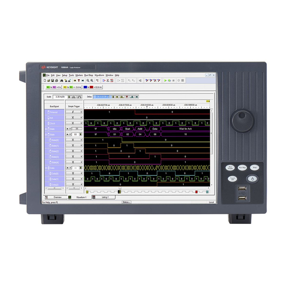
Keysight 16860 Series Logic Analyzer - At a Glance The Keysight Technologies 16860 series logic analyzers are portable logic analyzers that range from 34 to 136 logic acquisition channels, depending on the model. The 16860-series models provide features such as: •... -
Page 6: Features, Mainframe
Technologies for all service work, including troubleshooting. Contact your nearest Keysight Technologies Sales Office for more details. Contacting Keysight Technologies To locate a sales or service office near you, go to www.keysight.com/find/contactus. Keysight 16860 Series Portable Logic Analyzer Service Guide... -
Page 7: In This Service Guide
In This Service Guide This book is the service guide for the 16860 series logic analyzer. This service guide has seven chapters. Chapter 1, “General Information” contains information about the instrument, lists accessories for the module, gives specifications and characteristics of the instrument, and provides a list of the equipment required for servicing the instrument. - Page 8 Keysight 16860 Series Portable Logic Analyzer Service Guide...
-
Page 9: Table Of Contents
Contents Keysight 16860 Series Logic Analyzer - At a Glance Model Comparison Features, Mainframe Supplied Accessories Optional Accessories In This Service Guide 1 General Information Accessories Probes, Cables, and Accessories Software Specifications Characteristics 2 Preparing for Troubleshooting or Performance Testing Operating Environment To apply power To clean the instrument... - Page 10 Contents Create Test Configuration Files Create Configuration File 1 - Multiple Clocks (no Marker) Create Configuration File 2 - Multiple Clocks (with Marker) Create Configuration File 3 - Single Clock (no Marker) Create Configuration File 4 - Single Clock with Marker Determine Maximum Data Rate for Multiple Clocks Mode Pod 1 Clock - Maximum Clock Rate Pod 1 Clock - Setup for Maximum Data Rate...
- Page 11 Contents To troubleshoot system power problems Power Supplies To run the self-tests Logic Acquisition Self-Test Descriptions To exit the test system To restore the system software Contacting Keysight Service/Support To test the logic acquisition cables 6 Removing, Replacing, or Returning 16860 Series Logic Analyzer Assemblies Before you Start Repair Tools Needed Back Up Data and License Files...
- Page 12 Contents Keysight 16860 Series Portable Logic Analyzer Service Guide...
- Page 13 Keysight 16860 Series Portable Logic Analyzer Service Guide General Information Accessories / 14 Software / 14 Specifications / 15 Characteristics / 16 This chapter lists the accessories and some of the specifications and characteristics for testing and servicing the 16860 series logic analyzer. See the 16860 Series logic analyzer’s online help for a full listing of all specifications and characteristics.
-
Page 14: General Information
General Information Accessories One or more of the following accessories, sold separately, are required to set up and operate the 16860 series logic analyzer for testing and servicing it. Probes, Cables, and Accessories Refer to the 16860 series logic analyzer Data Sheet (5992-1723EN) on www.keysight.com to get a list of supported interposers, probes, and cables for 16860 series logic analyzer. -
Page 15: Specifications
General Information Specifications The specifications are the performance standards against which the product is tested. Table 1 Maximum State Data Rate Specification for the 16860 Series Logic Analyzers 350 MHz 700 MHz 350 MHz (Base configuration) (Option 700) (Base configuration) Single Clock Single Clock Multiple Clocks... -
Page 16: Characteristics
General Information Characteristics For a full listing of all specifications and characteristics, see the Keysight 16860 series logic analyzer Data Sheet, literature part number 5992-1723EN available on Keysight’s web site (www.keysight.com). Keysight 16860 Series Portable Logic Analyzer Service Guide... - Page 17 Keysight 16860 Series Portable Logic Analyzer Service Guide Preparing for Troubleshooting or Performance Testing Operating Environment / 18 To apply power / 19 To clean the instrument / 20 To start the user interface / 21 To test the 16860 series logic analyzer / 22 This chapter provides instructions for preparing the 16860 series logic analyzer for troubleshooting or servicing it.
-
Page 18: Preparing For Troubleshooting Or Performance Testing
Preparing for Troubleshooting or Performance Testing Operating Environment The operating environment specifications are listed in the Keysight 16860 series logic analyzer Data Sheet, literature part number 5992-1723EN available on Keysight’s web site (www.keysight.com). Note the non-condensing humidity limitation. Condensation within the instrument can cause poor operation or malfunction. -
Page 19: To Apply Power
Preparing for Troubleshooting or Performance Testing To apply power Connect the supplied power cord to the instrument and to the power source. This instrument autodetects the line voltage from 100 VAC to 240 VAC. It is equipped with a three-wire power cable. When connected to an appropriate AC power outlet, this cable grounds the instrument cabinet. -
Page 20: To Clean The Instrument
Preparing for Troubleshooting or Performance Testing To clean the instrument If the instrument requires cleaning: Remove power from the instrument. Clean the external surfaces of the instrument with a soft cloth dampened with water. Make sure that the instrument is completely dry before reconnecting it to a power source. Keysight 16860 Series Portable Logic Analyzer Service Guide... -
Page 21: To Start The User Interface
Preparing for Troubleshooting or Performance Testing To start the user interface Start the Keysight Logic and Protocol Analyzer application from the Start menu or using a shortcut. On the desktop, the Keysight Logic Analyzer icon looks like: Refer to the Keysight Logic and Protocol Analyzer application’s on-line help for information on how to operate the user interface. -
Page 22: To Test The 16860 Series Logic Analyzer
Preparing for Troubleshooting or Performance Testing To test the 16860 series logic analyzer The 16860 series logic analyzer does not require an operational accuracy calibration or adjustment. After installing the instrument, you can test and use the instrument. • If you require a test to verify logic analyzer’s performance with the specifications, see “Testing 16860 Series Logic Analyzers Performance"... -
Page 23: Testing 16860 Series Logic Analyzers Performance
Keysight 16860 Series Portable Logic Analyzer Service Guide Testing 16860 Series Logic Analyzers Performance Perform the Self-Tests / 25 Equipment Required for the Performance Test / 26 Assemble the SMA/Flying Lead Test Connectors / 27 Set Up the Test Equipment / 30 Connect the Test Equipment / 33 Test the 16860 series Logic Analyzer / 35 Create Test Configuration Files / 36... - Page 24 Logic Analyzer will be measured separately. In the multiple clock mode, performance of all 4 clocks will be measured, except for the 16861A only 2 pods. In the single clocking mode, data from up to 8 pods (depending on model) will be verified, one pod at a time.
-
Page 25: Perform The Self-Tests
Testing 16860 Performance Perform the Self-Tests Power the 16860 series analyzer on and start the Logic Analyzer application. Before performing the self- tests, disconnect all probes from the logic analyzer. Select Help->Self-Test... from the main menu. The Analysis System Self Tests window appears. From the Select suites list, select the option displayed for 16860. -
Page 26: Equipment Required For The Performance Test
Testing 16860 Performance Equipment Required for the Performance Test The following equipment is required for the performance test procedure. Table 2 Equipment Required Equipment Critical Specification Recommended Model/Part Pulse Generator ≥ 800 MHz, two channels, differential outputs, Keysight 81134A or equivalent (Qty: 1) 150-180 ps rise/fall time (if faster, use transition time converters) -
Page 27: Assemble The Sma/Flying Lead Test Connectors
Testing 16860 Performance Assemble the SMA/Flying Lead Test Connectors The SMA/Flying Lead test connectors provide a high-bandwidth connection between the logic analyzer and the test equipment. The following procedure explains how to fabricate the four required test connectors. Table 3 Materials Required for SMA/Flying Lead Test Connectors Material Critical Specification... - Page 28 Testing 16860 Performance Solder the pin strip to the SMA board mount connector: a Solder the leads on the left side of the pin strip to the center conductor of the SMA connector as shown in the diagram below. b Solder the leads on the right side of the pin strip to the inside of the SMA connector's frame as shown in the diagram below.
- Page 29 Testing 16860 Performance c The finished test connector is shown in the pictures below. Keysight 16860 Series Portable Logic Analyzer Service Guide...
-
Page 30: Set Up The Test Equipment
Testing 16860 Performance Set Up the Test Equipment This section explains how to set up the test equipment for the maximum state data rate test. Connect Transition Time Converters (if required) to each of the four outputs of the pulse generator: Channel 1 OUTPUT, Channel 1 OUTPUT (not), Channel 2 OUTPUT, Channel 2 OUTPUT (not). - Page 31 Testing 16860 Performance • Option 700: Test at 700 Mb/s plus 2% (714 Mb/s). Set the generator to half this or 357 MHz. This includes the frequency uncertainty of the pulse generator, cabling, and a test margin. If you are using an 81134A pulse generator, the frequency accuracy is ±0.005% of setting. b Set the rest of the pulse generator parameters to the values shown in the following tables.
- Page 32 Testing 16860 Performance Keysight 16860 Series Portable Logic Analyzer Service Guide...
-
Page 33: Connect The Test Equipment
Connect one U4203A Flying Lead Probe Set to Pods 1/2 of the 16860 series logic analyzer. If not a 16861A, connect one U4203A Flying Lead Probe Set to Pods 3/4 of the analyzer. Connect the Pod 1 U4203A Flying Lead Probe Set's CLK lead to the pin strip of the SMA/Flying Lead connector at the pulse generator's Channel 1 OUTPUT. - Page 34 Testing 16860 Performance Keysight 16860 Series Portable Logic Analyzer Service Guide...
-
Page 35: Test The 16860 Series Logic Analyzer
Testing 16860 Performance Test the 16860 series Logic Analyzer The following sections explain how to measure the maximum state data rate. Record the logic analyzer's model and serial number in the Performance Test Record (see page 77). Record your work order number (if applicable) and today's date. Record the test equipment information in the “Test Equipment Used”... -
Page 36: Create Test Configuration Files
Testing 16860 Performance Create Test Configuration Files The test consists of multiple setups to test all the various analyzer modes. To make this easier, 4 configuration files will be created. The configuration files will then be used as starting points for the measurement setups. - Page 37 Testing 16860 Performance Apply this to all Pods and Clocks by clicking the Apply to All Other Pods and Clocks button. Click Done to close the Threshold dialog. Select the Sampling tab. In the Sampling dialog, set the Acquisition mode to State - Synchronous Sampling. 10 Set the State Options to Multiple Clocks.
- Page 38 Testing 16860 Performance 11 Set Pod1 Clock to Both Edges. Set other clocks to Don't Care. 12 Set the Trigger Position to 100% Poststore. Set Acquisition Depth to 256K. 13 Close the Sampling dialog by clicking OK. 14 Select the Listing Window by selecting Window and then Listing. Keysight 16860 Series Portable Logic Analyzer Service Guide...
-
Page 39: Create Configuration File 2 - Multiple Clocks (With Marker)
Testing 16860 Performance 15 Save the configuration by selecting File then Save As …. 16 In the Save As dialog, type the file name MultipleClocks_NoMarker.ala. For file options, select Setup Only. Then click Save. Create Configuration File 2 - Multiple Clocks (with Marker) Start with the MultipleClocks_NoMarker configuration file. - Page 40 Testing 16860 Performance Close the Analyzer Setup Dialog Window by clicking OK. Click the Run button. The analyzer needs to have data before the Marker can be added. Add a new marker by selecting Marker and then New. In the New Marker dialog, change the Position information. Select Value in the drop down. 10 Open the Value dialog by clicking the Occurs button.
- Page 41 Testing 16860 Performance 12 In the Value dialog, select the Properties... button. 13 In the Value Properties dialog, select Stop repetitive run when value is not found. 14 Close the Marker dialogs by clicking OK several times. 15 Save the configuration by selecting File then Save As …. 16 In the Save As dialog, type the file name MultipleClocks_WithMarker.ala.
-
Page 42: Create Configuration File 3 - Single Clock (No Marker)
Testing 16860 Performance Create Configuration File 3 - Single Clock (no Marker) Start with the MultipleClocks_NoMarker configuration file. Select File then Open. In the Open dialog select the file and then open. If asked about saving the current configuration, click No. Ensure that there is a U4203A connected to Pods 1 and 2. -
Page 43: Create Configuration File 4 - Single Clock With Marker
Testing 16860 Performance In the Save As dialog, type the file name SingleClock_NoMarker.ala. For file options, select Setup Only. Then click Save. Create Configuration File 4 - Single Clock with Marker Start with the MultipleClocks_WithMarker configuration file. Select File and then Open. In the Open dialog select the file then open. - Page 44 Testing 16860 Performance In the Save As dialog, type the file name SingleClock_WithMarker.ala. For file options, select Setup Only. Then click Save. Keysight 16860 Series Portable Logic Analyzer Service Guide...
-
Page 45: Determine Maximum Data Rate For Multiple Clocks Mode
Testing 16860 Performance Determine Maximum Data Rate for Multiple Clocks Mode The multiple clocks test measures the maximum data rate of each of the four clocks used for this mode: Pod1, Pod2, Pod3, Pod4. Each Pod / clock is measured separately. The measurement is done in two parts: •... -
Page 46: Pod 1 Clock - Setup For Maximum Data Rate
Testing 16860 Performance If the analyzer displays an error again, lower the frequency by 1MHz and run again. If the test does not display an error, increase the frequency by 1 MHz and run again. Continue changing the frequency and running unit the frequency can no longer be increased and the error message not displayed. - Page 47 Testing 16860 Performance Select the Assign Busses/Signals. In the Buses/Signals section of the dialog, ensure that the check box next to My Bus 1 is checked and the 4 data bits 0-3. Click OK. Select Full time/voltage scan. Keysight 16860 Series Portable Logic Analyzer Service Guide...
- Page 48 Testing 16860 Performance In the dialog, set Do full time/voltage scan and Show time/voltage diagram. Run Eye Scan by clicking the Run This Measurement button. If the scan does not fill the scan area, right click in the scan area and select Autoscale all. The waveform should now fill the Eye Scan area.
- Page 49 Testing 16860 Performance 10 If all sample positions are not in the same eye, then click the Plus sign to expand My Bus 1. 11 Use the mouse to grab the bits that are not in the correct eye and move them into the right eye. 12 After all bit sample positions are in the correct eye, right-click in the My Bus 1 Scan area and select Set to Suggested.
-
Page 50: Pod 1 Clock - Measuring Maximum Data Rate
Testing 16860 Performance 13 After setting to suggested, all bits should be centered in their own eye near -.5 ns. 14 Close Eye Scan by clicking OK. 15 Close the Sampling dialog by clicking OK. Pod 1 Clock - Measuring Maximum Data Rate After setting the sample positions, the data capture can now be verified at the frequency found in the clock rate section. -
Page 51: Pod 2 Clock - Maximum Clock Rate
Testing 16860 Performance If the clock rate is too high, this error message may occur. If either of these messages occur, the generator frequency should be lowered, Eye Scan run and the test rerun. Lower the generator frequency by 1 MHz and rerun the test. If bad data is found or an error message occurs, decrease the pulse generator frequency by 1 NOTE MHz and rerun Eye Scan to find the sample position. - Page 52 Testing 16860 Performance Open the Sampling Tab in the Analyzer Setup dialog by clicking the Sampling Setup Icon. In the clock assignment area, set Pod 1 Clock to Don't Care and set Pod 2 Clock to Both Edges. Close the dialog by clicking OK. Set the generator frequency to 357 MHz as a starting point.
-
Page 53: Pod 2 Clock - Setup For Maximum Data Rate
Testing 16860 Performance 17 Click the Stop toolbar button to stop the data acquisition. 18 Note the generator frequency setting this will be used in the next section to verify the data rate. Pod 2 Clock - Setup for Maximum Data Rate Verify that the Generator is set to the frequency found in the last section as a starting point. -
Page 54: Pod 2 Clock - Measuring Maximum Data Rate
Testing 16860 Performance Close the dialog boxes by clicking OK. Pod 2 Clock - Measuring Maximum Data Rate Click the Run Repetitive icon. Let the logic analyzer run for about 1 minute. The analyzer will acquire data and the Listing Window will continuously update. A marker search window will appear and show progress. -
Page 55: Pod 3 Clock - Maximum Clock Rate
Testing 16860 Performance For this Pod's Clock, record the generator frequency and the Data Rate in the "Maximum State Data Rate" section of the “Performance Test Record" on page 77. Remember that the data rate is twice the generator frequency. Pod 3 Clock - Maximum Clock Rate This section is only applicable to models: 16862A, 16863A &... -
Page 56: Pod 3 Clock - Setup For Maximum Data Rate
Testing 16860 Performance 11 Without changing the frequency, clear the message by clicking OK. Then click the Run Repetitive toolbar button to start a repetitive run again at the same frequency. Running at the same frequency checks to see if the error message was caused by noise due to the changing of the generator frequency. -
Page 57: Pod 3 Clock - Measuring Maximum Data Rate
Testing 16860 Performance Unassign the data bits from Pod1. Assign bits 2, 6, 10, and 14 of Pod 3. Open the Sampling tab. In the clock assignment area, set Pod 1 Clock to Don't Care and set Pod 3 Clock to Both Edges. Adjust the sample position using the procedure described earlier by clicking the Eye Scan: Sample Position and Thresholds button. - Page 58 Testing 16860 Performance This section is only applicable to models: 16862A, 16863A & 16864A. NOTE Select the Run Repetitive icon. Let the logic analyzer run for about 1 minute. The analyzer will acquire data and the Listing Window will continuously update. A marker search window will appear and show progress.
-
Page 59: Pod 4 Clock - Maximum Clock Rate
Testing 16860 Performance Pod 4 Clock - Maximum Clock Rate This section is only applicable to models: 16862A, 16863A & 16864A. NOTE Load the MultipleClocks_NoMarker.ala configuration file. If asked to save the current configuration file, click No. Disconnect the U4203A Flying Lead Probe Set from channels 1 & 2 of the 81134A pulse generator output (Bits 2, 6, 10, 14) and clock leads. -
Page 60: Pod 4 Clock - Setup For Maximum Data Rate
Testing 16860 Performance 16 Wait for logic analyzer to complete 100 acquisitions at the new pulse generator frequency without displaying any error. If an error is displayed, decrease the pulse generator frequency by 1 MHz and then again wait for 100 acquisitions at this new frequency without any error. Repeat this step until you get 100 acquisitions without any error display. -
Page 61: Pod 4 Clock - Measuring Maximum Data Rate
Testing 16860 Performance Adjust the sample position using the procedure described earlier by selecting "Eye Scan: Sample Position and Thresholds". Close the dialog windows by clicking OK. Pod 4 Clock - Measuring Maximum Data Rate This section is only applicable to models: 16862A, 16863A & 16864A. NOTE Select the Run Repetitive icon . - Page 62 Testing 16860 Performance If either of these messages occur, the generator frequency should be lowered, Eye Scan should be rerun and the test should be rerun. Lower the generator frequency by 1 MHz and rerun the test. After the analyzer runs for about 1 minute, select the Stop button to stop the acquisition.
-
Page 63: Determine Maximum Data Rate For Single Clock Mode
Testing 16860 Performance Determine Maximum Data Rate for Single Clock Mode The single clock test measures the maximum data rate for the single clock mode. This test measures data rates for Rising, Falling, and Both Edge modes. Using Both Edge clocking, it verifies data rates on all pods. - Page 64 Testing 16860 Performance Click the Run Repetitive toolbar button to start a repetitive run on the logic analyzer for acquiring data repeatedly. Acquired data will start appearing in the Listing window. Start increasing the frequency on the pulse generator by 1 MHz increments while simultaneously observing the logic analyzer data acquisition status.
-
Page 65: Single Clock Rising Edge - Pod 1 Data - Setup For Maximum Data Rate
Testing 16860 Performance Single Clock Rising Edge - Pod 1 Data - Setup for Maximum Data Rate To measure the maximum data rate, the starting frequency will be the frequency found in the section above. A new configuration file will be used that has a marker setup to verify that the data patterns are correct. -
Page 66: Single Clock Rising Edge - Pod 1 Data - Measuring Maximum Data Rate
Testing 16860 Performance Single Clock Rising Edge - Pod 1 Data - Measuring Maximum Data Rate Select the Run Repetitive icon. Let the logic analyzer run for about 1 minute. The analyzer will acquire data and the Listing Window will continuously update. A marker search window will appear and show progress. -
Page 67: Single Clock Falling Edge - Maximum Clock Rate
Testing 16860 Performance Single Clock Falling Edge - Maximum Clock Rate Load the SingleClock_NoMarker.ala configuration file.If asked to save the current configuration file, click No. Verify that the Generator is set to 714 MHz as a starting point. Open the Sampling tab in the Analyzer Setup dialog by clicking the Sampling Setup Icon. In the clock assignment area, set Pod 1 Clock to Falling Edge. -
Page 68: Single Clock Falling Edge - Pod 1 Data - Setup For Maximum Data Rate
Testing 16860 Performance Without changing the frequency, clear the message by clicking OK. Then click the Run Repetitive toolbar button to start a repetitive run again at the same frequency. Running at the same frequency checks to see if the error message was caused by noise due to the changing of the generator frequency. -
Page 69: Single Clock Falling Edge - Pod 1 Data - Measuring Maximum Data Rate
Testing 16860 Performance Open the Sampling tab in the Analyzer Setup dialog by clicking the Sampling Setup Icon. In the clock assignment area, set Pod 1 Clock to Falling Edge. Adjust the sample position using the procedure described earlier by clicking the Eye Scan: Sample Position and Thresholds button. -
Page 70: Single Clock Both Edges - Maximum Clock Rate
Testing 16860 Performance If either of these messages occur, the generator frequency should be lowered, Eye Scan rerun and the test rerun. Lower the generator frequency by 1 MHz and rerun the test. After the analyzer runs for about 1 minute select the Stop button to stop the acquisition. - Page 71 Testing 16860 Performance Close the dialog windows by clicking OK. Click the Run Repetitive toolbar button to start a repetitive run on the logic analyzer for acquiring data repeatedly.Acquired data will start appearing in the Listing window. Start increasing the frequency on the pulse generator by 1 MHz increments while simultaneously observing the logic analyzer data acquisition status.
-
Page 72: Single Clock Both Edges - Pod 1 Data - Setup For Maximum Data Rate
Testing 16860 Performance 15 Click the Stop toolbar button to stop the data acquisition. 16 Note the generator frequency setting. This will be used in the next section to verify the data rate. Single Clock Both Edges - Pod 1 Data - Setup for Maximum Data Rate On the 81134A, select the channel 2 setup screen. -
Page 73: Single Clock Both Edges - Pod 2 Data - Setup For Maximum Data Rate
Testing 16860 Performance If the clock rate is too high, this error message may occur. If either of these messages occur, the generator frequency should be lowered, Eye Scan should be rerun and the test should be rerun. Lower the generator frequency by 1 MHz and rerun the test. After the analyzer runs for about 1 minute, select the Stop button to stop the acquisition. -
Page 74: Single Clock Both Edges - Pod 2 Data - Measuring Maximum Data Rate
Testing 16860 Performance • Bits 2 & 10 to Channel 2 Output • Bits 6 & 14 to Channel 2 Output (not) Open the Bus/Signal Setup dialog by clicking the Setup Icon in the toolbar. Unassign the data bits from Pod1. Assign bits 2, 6, 10, and 14 of Pod 2. -
Page 75: Single Clock Both Edges - Pods 3 To 8
Testing 16860 Performance If the clock rate is too high, the following error message may occur. If either of these messages occur, the generator frequency should be lowered, Eye Scan should be rerun, and the test should be rerun. Lower the generator frequency by 1 MHz and rerun the test. After the analyzer runs for about 1 minute, select the Stop button to stop the acquisition. -
Page 76: Conclude The State Data Rate Tests
Testing 16860 Performance Conclude the State Data Rate Tests Perform the following steps to properly shut down the logic analyzer session after completing the state mode tests. End the test. From the Main menu, select File > Exit. In the dialog "Do you want to save the current configuration?", click No. -
Page 77: Performance Test Record
Testing 16860 Performance Performance Test Record LOGIC ANALYZER MODEL NO.: 16861A, 16862A, 16863A, 16864A Logic Analyzer Serial No. Work Order No. Date: Recommended Test Interval - 2 Year/4000 hours Recommended next testing: TEST EQUIPMENT USED Pulse Generator Model No. Pulse Generator Serial No. - Page 78 Testing 16860 Performance TEST RESULTS - Maximum State Data Rate Mode: Single Clock Data Rate Generator Frequency Measured (Spec) (MHz) Data Rate (Mb/s) (Mb/s) Clock - Rising Edge (Data Pod 1) Clock - Falling Edge (Data Pod 1) Clock - Both Edges (Data Pod 1) 1400 Clock - Both Edges (Data Pod 2) 1400...
-
Page 79: Calibrating
Keysight 16860 Series Portable Logic Analyzer Service Guide Calibrating Calibration Strategy / 80 This chapter provides instructions for calibrating the16860 series logic analyzer. -
Page 80: Calibration Strategy
Calibrating Calibration Strategy The 16860 series logic analyzer does not require any periodic adjustments or calibration by the user to ensure operational accuracy. However, Keysight recommends that performance of the 16860 series logic analyzer be tested against its specifications at two-year intervals. This testing is required in order to obtain calibration certification. -
Page 81: Troubleshooting
The service strategy for the 16860 logic analyzer is the replacement of defective assemblies. You can send this logic analyzer to Keysight Technologies for all service work, including troubleshooting. Contact your nearest Keysight Technologies Sales Office for more details. -
Page 82: To Use The System Troubleshooting Flowcharts
Troubleshooting To use the system troubleshooting flowcharts Flowcharts are the primary tool used to isolate defective assemblies. The flowcharts refer to other tests to help isolate the trouble. The circled references on the charts indicate connections with the other flowcharts or other parts within the same flowchart. Start your troubleshooting at the top of the first flowchart (Figure 1 on page 83). - Page 83 Troubleshooting Figure 1 System Troubleshooting Flowchart Keysight 16860 Series Portable Logic Analyzers Service Guide...
- Page 84 Troubleshooting Figure 2 System Power Troubleshooting Flowchart Keysight 16860 Series Portable Logic Analyzers Service Guide...
- Page 85 Troubleshooting Figure 3 System Display Troubleshooting Flowchart Keysight 16860 Series Portable Logic Analyzers Service Guide...
- Page 86 Troubleshooting Figure 4 System Boot Up Troubleshooting Flowchart Keysight 16860 Series Portable Logic Analyzers Service Guide...
-
Page 87: To Use The Logic Acquisition Troubleshooting Flowcharts
Start your troubleshooting at the top of the first flowchart. If the instrument still doesn't work correctly after completing all the procedures described in the flowchart, return it to Keysight Technologies for repair. Be sure to include a note describing the problem in detail. - Page 88 Troubleshooting Figure 5 Logic Acquisition Troubleshooting Flowchart Keysight 16860 Series Portable Logic Analyzers Service Guide...
-
Page 89: To Troubleshoot System Power Problems
Troubleshooting To troubleshoot system power problems If the system warns you it is powering down before it powers down, it is a fan/overtemp problem. If it just powers down, it is a power supply problem. If the lights do not come on and if the system powers up momentarily when you plug it in, make sure the power button hasn't become jammed or stuck in the pushed-in position. -
Page 90: To Run The Self-Tests
Troubleshooting To run the self-tests The self-tests check the functional operation of the logic analyzer. Perform the self-tests as an acceptance test when receiving the logic analyzer or when the logic analyzer is repaired. In the Keysight Logic and Protocol Analyzer application, click Help>Self Test... In the Analysis System Self Test dialog, double-click the test you want to run. -
Page 91: Logic Acquisition Self-Test Descriptions
Troubleshooting Logic Acquisition Self-Test Descriptions The self-tests for the logic analyzer identify the correct operation of major functional areas in the module. Interface FPGA Version Test This test verifies that the FPGA program is a version that the software can use. This is necessary because new features will be added to the 16860 logic analyzer that will require both new software and new FPGA bits. -
Page 92: To Exit The Test System
Troubleshooting Comparator Programming Test The purpose of this test is to verify the programming path to each of the comparators. Comparator/DAC Test This test is executed only if all probes are detached. This test uses the pod, bonus, and calibration DACs, the calibration oscillator (implemented in the interface FPGA), the comparators, the connections between the comparators and the Analysis chip, and the activity indicators in the Analysis chip. -
Page 93: To Restore The System Software
Troubleshooting To restore the system software Restoring your system software might be necessary for the following reasons: • Hard drive failure. • Virus in the system or unstable system. • Intentional disk clean - for example if you are passing the system to another team or returning it to a rental company and you do not want any data left on it. - Page 94 Troubleshooting After a few seconds, Logic Analyzer automatically starts with the option selected in the Windows Boot Manager. Select the Keysight Recovery system option in the Windows Boot Manager screen using the arrow keys and then press Enter. The recovery process starts preparing the system for recovery and displays the following screen with options to choose.
- Page 95 Troubleshooting The recovery process starts. If the recovery process is able to restore the system software successfully, then the following screen is displayed. Click OK to proceed. You Logic Analysis system now reboots to Windows 7. The Windows Boot Manager screen is displayed with Microsoft Windows 7 as the default selection. The system automatically starts with this default selection.
-
Page 96: Contacting Keysight Service/Support
Troubleshooting There are situations when you are not able to run the recovery process, (for instance, NOTE when the hard disk drive of your system fails) or when running the recovery process does not recover your system software. In such situations, you can send your Logic Analysis system for hard disk repair/replacement to Keysight. -
Page 97: To Test The Logic Acquisition Cables
Troubleshooting To test the logic acquisition cables This test allows you to functionally verify the logic analyzer cable and the flying lead probe of any of the logic analyzer pods. Only one probe and cable can be tested at a time. Repeat this test for each probe and cable to be tested. - Page 98 Troubleshooting Pod 1 Pod 2 Pod 4 connector Pod 5 connector Set up the stimulus board a Configure the oscillator select switch S1 according to the following settings: • S1 0 (Off). • S2 1 (On). • S3 0 (Off). •...
- Page 99 Troubleshooting Disable all analyzers except the one being tested. This simplifies the instructions and makes module initialization faster. a Select the Overview tab at the bottom of the main window. Set up the bus: a In the Overview window, select Setup -> Bus/Signal... from the module’s drop-down menu. b Scroll if necessary to view the pods you are testing.
- Page 100 Troubleshooting d Channels 7 through 0 are already assigned by default. Assign pod 2 channels 15 through 0 and pod 1 channels 15 through 8 by clicking and dragging from the left-most channel box to the right-most channel box. Your display should look like the lower picture when you are done. Select the State sampling mode and set the State Clock options: a Select the Sampling tab of the Analyzer Setup window.
- Page 101 Troubleshooting Adjust sampling positions: a Click the Eye Scan: Thresholds and Sample Positions button. The Eyescan - Sample Positions and Threshold Settings dialog will appear. b In the “Buses/Signals” section of the Eyescan - Sample Positions and Threshold Settings dialog, make sure the check box next to “My Bus 1” is checked. c Click Edit, select the Do time scan only option as the scan dimension and then select the Lock Thresholds checkbox.
- Page 102 Troubleshooting e Make sure the sampling positions are set properly, and re-align any stray channels if necessary. Select OK to close the Eyescan - Sample Positions and THreshold Settings window. g Select OK to close the Analyzer Setup window. Switch to the Listing window by selecting the Listing tab at the bottom of the main window. 10 Click the Run icon .
- Page 103 Troubleshooting 12 Repeat the cable test for pods 3 and 4: a Connect the logic analyzer’s pod 3 cable to the stimulus board’s pod 4 connector. b Connect the logic analyzer’s pod 4 cable to the stimulus board’s pod 5 connector. c In the Buses/Signals tab of the Analyzer Setup window, assign the pod 3 and 4 channels to “My Bus 1”.
- Page 104 Troubleshooting Keysight 16860 Series Portable Logic Analyzers Service Guide...
-
Page 105: Removing, Replacing, Or Returning 16860 Series Logic Analyzer Assemblies
If the 16860 series logic analyzer’s assemblies/parts are found faulty and need to be repaired/replaced, refer to the procedures included in this chapter that guide you how to repair, replace, or return these to Keysight Technologies. Service instructions included in this chapter are for trained service CAUTION personnel. -
Page 106: Before You Start
Removing, Replacing, or Returning 16860 Series Logic Analyzer Assemblies Before you Start Before you start any repair or replacement work on a 16860 logic analyzer, it is recommended that you perform the tasks described in this section and carefully read and follow the cautions and warnings included in this section. -
Page 107: Back Up Data And License Files
For Logic analyzers that use the Keysight License Manager, you can find the license files in the following directory: C:\Program Files\Agilent\Licensing\ If you lose the license files, you can obtain new licenses from Keysight Technologies by providing the licensing host ID. To obtain the licensing host ID •... - Page 108 Removing, Replacing, or Returning 16860 Series Logic Analyzer Assemblies Method to Power Off Description Using the Windows Shutdown 1. On the logic analyzer desktop, click Start >Shut Down. This method of power off does the following: • Closes all programs that are running. •...
-
Page 109: Removing And Replacing The Hard Drive, Acquisition Bezel, And Cover
Removing, Replacing, or Returning 16860 Series Logic Analyzer Assemblies Removing and Replacing the Hard Drive, Acquisition Bezel, and Cover Prerequisites Ensure that you have completed the tasks listed in the “Before you Start topic. If the accessory pouch is attached to the logic analyzer, detach the pouch using its four corners. To remove the hard drive, bezel, and cover Using a flat screwdriver or fingers, loosen the two screws holding the logic analyzer removable hard drive. - Page 110 Removing, Replacing, or Returning 16860 Series Logic Analyzer Assemblies Using a Torx T10 screwdriver, remove the four screws that secure the acquisition bezel, and then remove the acquisition bezel. Using a Torx T20 screwdriver, remove the two screws that secure the handle assembly, and then remove the handle assembly.
- Page 111 Removing, Replacing, or Returning 16860 Series Logic Analyzer Assemblies Gently pull the cover upward to remove it. Reverse this procedure to replace the cover, bezel, or hard drive. When reinstalling the handle assembly, ensure that the screws are CAUTION torqued to 2.372 Newton meters (21 inch pounds) so that they do not work themselves loose.
-
Page 112: Removing And Replacing The Front Panel
Removing, Replacing, or Returning 16860 Series Logic Analyzer Assemblies Removing and Replacing the Front Panel Prerequisites Ensure that you have: • completed the tasks listed in the “Before you Start topic. • removed the cover using the procedure listed in “Removing and Replacing the Hard Drive, Acquisition Bezel, and Cover"... - Page 113 Removing, Replacing, or Returning 16860 Series Logic Analyzer Assemblies Using a Torx T10 screwdriver, remove the eight screws (as indicated in the photos below) that secure the front panel to the chassis. The left and right sides of the instrument are displayed in the photos below.
-
Page 114: Disassembling The Front Panel
Removing, Replacing, or Returning 16860 Series Logic Analyzer Assemblies Reverse this procedure to install the front panel assembly. Disassembling the Front Panel After you have removed the front panel assembly using the procedure described above, you can disassemble the front panel using the procedure given below. Remove the knob on the front panel by gently pulling the knob forward. - Page 115 Removing, Replacing, or Returning 16860 Series Logic Analyzer Assemblies Remove the touchscreen cable from the front panel. To do this, first unclip the three clips that hold this cable to the front panel. These clips are pointed out in the photo below. Then disconnect the cable from the two locations encircled in red in the photo below.
- Page 116 Removing, Replacing, or Returning 16860 Series Logic Analyzer Assemblies Remove the USB Controller Board from the front panel by removing the two screws encircled in the photo below. If necessary, use a Torx T10 screwdriver to remove these. Using a Torx T10 screwdriver, remove the six screws that secure the LCD assembly to the front bezel.
- Page 117 Removing, Replacing, or Returning 16860 Series Logic Analyzer Assemblies c Remove the other three screws that secure the LCD panel to the LCD assembly. These three screws are encircled in the photo below. Then remove the LCD panel while taking care of the flat cable on the left side of the LCD panel.
-
Page 118: Removing And Replacing The Fan Deck
Removing, Replacing, or Returning 16860 Series Logic Analyzer Assemblies Removing and Replacing the Fan Deck Prerequisites Ensure that you have: • completed the tasks listed in the “Before you Start topic. • removed the cover using the procedure listed in “Removing and Replacing the Hard Drive, Acquisition Bezel, and Cover"... -
Page 119: Removing And Replacing The Acquisition Tray
Removing, Replacing, or Returning 16860 Series Logic Analyzer Assemblies Removing and Replacing the Acquisition Tray Ensure that you have: • completed the tasks listed in the “Before you Start topic. • removed the cover using the procedure listed in “Removing and Replacing the Hard Drive, Acquisition Bezel, and Cover"... - Page 120 Removing, Replacing, or Returning 16860 Series Logic Analyzer Assemblies Nine screws from left and right sides of the chassis Two screws from rear of the chassis Carefully slide the acquisition tray out of the chassis while ensuring that the gasket on the tray does not snag during removal.
-
Page 121: Removing And Replacing The Duct
Removing, Replacing, or Returning 16860 Series Logic Analyzer Assemblies Removing and Replacing the Duct Prerequisites Ensure that you have: • completed the tasks listed in the “Before you Start topic. • removed the cover using the procedure listed in “Removing and Replacing the Hard Drive, Acquisition Bezel, and Cover"... -
Page 122: Removing And Replacing The Motherboard
Removing, Replacing, or Returning 16860 Series Logic Analyzer Assemblies Removing and Replacing the Motherboard Prerequisites Ensure that you have: • completed the tasks listed in the “Before you Start topic. • removed the cover using the procedure listed in “Removing and Replacing the Hard Drive, Acquisition Bezel, and Cover"... - Page 123 Removing, Replacing, or Returning 16860 Series Logic Analyzer Assemblies Using a Torx T15 screwdriver, remove the six screws that secure the motherboard. These are indicated in the photo below. Remove the motherboard. Reverse this procedure to install the motherboard. Keysight 16860 Series Portable Logic Analyzer Service Guide...
-
Page 124: Removing And Replacing The Fib Board
Removing, Replacing, or Returning 16860 Series Logic Analyzer Assemblies Removing and Replacing the FIB Board Prerequisites Ensure that you have: • completed the tasks listed in the “Before you Start topic. • removed the cover using the procedure listed in “Removing and Replacing the Hard Drive, Acquisition Bezel, and Cover"... - Page 125 Removing, Replacing, or Returning 16860 Series Logic Analyzer Assemblies Remove the FIB board by removing the two screws (displayed below) that secure the FIB board to the rear panel. Use a Torx T10 screwdriver. Slide the FIB board slightly forward, lift slightly, then slide it forward and out. Reverse this procedure to install the FIB board.
-
Page 126: Removing And Replacing The Power Supply Shroud And Power Supply
Removing, Replacing, or Returning 16860 Series Logic Analyzer Assemblies Removing and Replacing the Power Supply Shroud and Power Supply Hazardous voltages exist on the power supply. To avoid electrical shock, WARNING disconnect the power from the instrument before performing the following procedures. - Page 127 Removing, Replacing, or Returning 16860 Series Logic Analyzer Assemblies Lift the power supply shroud out and remove it. Disconnect the 12V STDBY power cables from the power supply Disconnect the AC power cable. Turn the chassis upside down and with a T10 Torx screwdriver, remove the four screws holding it in place.
- Page 128 Removing, Replacing, or Returning 16860 Series Logic Analyzer Assemblies Turn the chassis right side up and with a T10 Torx screwdriver, remove 1 screw through the side of the chassis, and then remove the power supply. Reverse this procedure to install the power supply and its shroud. Keysight 16860 Series Portable Logic Analyzer Service Guide...
-
Page 129: Returning The 16860 Series Logic Analyzer Or Its Assemblies
Removing, Replacing, or Returning 16860 Series Logic Analyzer Assemblies Returning the 16860 Series Logic Analyzer or its Assemblies Before shipping the 16860 series logic analyzer or its assemblies to Keysight Technologies, contact your nearest Keysight Technologies Sales Office for additional details. Information on contacting Keysight can be found at www.keysight.com/find/contactus. - Page 130 Removing, Replacing, or Returning 16860 Series Logic Analyzer Assemblies Keysight 16860 Series Portable Logic Analyzer Service Guide...
-
Page 131: Replaceable Parts
Keysight 16860 Series Portable Logic Analyzer Service Guide Replaceable Parts Ordering Replaceable Parts / 132 Replaceable Parts List / 133 This chapter contains information for identifying and ordering replaceable parts for a 16860 Series logic analyzer. -
Page 132: Ordering Replaceable Parts
Keysight Technologies. After you receive the exchange assembly, return the defective assembly to Keysight Technologies. A United States customer has 30 days to return the defective assembly. If you do not return the defective assembly within the 30 days, Keysight Technologies will charge you an additional amount. -
Page 133: Replaceable Parts List
All models in 16860-series 16860-66402 PCA, front panel 1686xA series All models in 16860-series 16860-66501 Tested acquisition board assembly, 34 and 68 channel for 16861A or 16861A 16862A 16862A 16860-66502 Tested acquisition board assembly, 102 and 136 channel for 16863A 16863A... - Page 134 16860-series 16860-68711 Motherboard assembly 1686xA 16860-69501 Refurbished tested acquisition board assembly, 34 and 68 channel for 16861A 16861A or 16862A, Exchange 16862A 16860-69502 Refurbished tested acquisition board assembly, 102 and 136 channel 16863A for 16863A or 16864A, Exchange 16864A 16861-22201...
- Page 135 Replaceable Parts Part Number Part Description For Product Model(s) 54964-41002 Foot - Tilt Lever All models in 16860-series 8121-2893 Cable-Assembly SATA Straight to Right-angle 26-AWG 7-Conductor All models in 0.5m Red 16860-series 8121-2894 Cable-Assembly SATA Straight to Right-angle 26-AWG 7-Conductor All models in 0.5m Blue 16860-series...
- Page 136 Replaceable Parts Keysight 16860 Series Portable Logic Analyzer Service Guide...
- Page 137 Index accessories, self-tests, acquisition, description, software, specifications, cable test E5379A cable, calibrating test, see also testing performance E5379A cables, calibration, testing performance, strategy, tests characteristics, self-tests, Check Disk, Windows Boot Manager, environment operating, features, flowcharts, flowcharts, troubleshooting, general information, operating environment, system, parts,...
- Page 138 Index Keysight 16860 Series Portable Logic Analyzer Service Guide...
Need help?
Do you have a question about the 16861A and is the answer not in the manual?
Questions and answers