Table of Contents
Advertisement
Quick Links
Advertisement
Table of Contents

Related Manuals for Keysight Technologies 16197A


Summary of Contents for Keysight Technologies 16197A
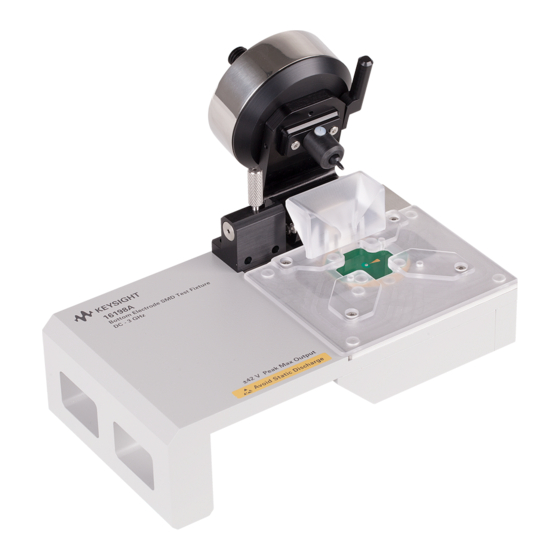
- Page 1 Keysight 16197A Bottom Electrode SMD Test Fixture Operation and Service Manual...
- Page 2 COVERING THE MATERIAL IN THIS perform, display, or disclose DOCUMENT THAT CONFLICT WITH commercial computer software or THESE TERMS, THE WARRANTY commercial computer software © Keysight Technologies, Inc. TERMS IN THE SEPARATE documentation. No additional 2011-2017 AGREEMENT WILL CONTROL. government requirements beyond...
-
Page 3: Table Of Contents
Assembly and Storage of 16197A ........ - Page 4 Short Impedance Check ...........70 Short-impedance Measurement Repeatability Check ......70 Keysight 16197A Operation and Service Manual...
-
Page 5: Installation Guide
Keysight 16197A Bottom Electrode SMD Test Fixture Operation and Service Manual Installation Guide This chapter describes the necessary operations to perform before using the delivered Bottom Electrode SMD Test Fixture16197A. Inspection before Unpacking Upon receiving the product package, inspect the packing box before unpacking to make sure it is not damaged. - Page 6 Installation Guide Inspection before Unpacking Figure 1-1 Package Contents of 16197A Keysight16197A Operation and Service Manual...
- Page 7 Installation Guide Inspection before Unpacking Table 1-1 Package Contents of 16197A Name Keysight part number Bottom-electrode SMD test fixture 16197A 16197-25005 Device guide Blank device guide 16197-25006 16197-00603 Electrode plate EIA/EIAJ -size, Shorting bar set 16191-29005 Shorting bar 1.0 x 0.5 x 0.5 16191-29006 Shorting bar 1.6 x 0.8 x 0.8...
-
Page 8: Assembly And Storage Of 16197A
Assembly and Storage of 16197A Assembly and Storage of 16197A The 16197A is delivered in a carrying case, disassembled into a pressure unit and an electrode unit. Assemble the fixture before use. Disassemble the fixture when storing it in the carrying case. -
Page 9: Storage
Storage Figure 1-3 Installing the Magnifying Glass Storage Before storing the 16197A, remove the pressure unit from the electrode unit (Figure 1-4) and loosen the pressure adjusting nut on the pressure unit (Figure 1-5). Also remove the magnifying glass, if installed. - Page 10 Installation Guide Storage Figure 1-5 Pressure Adjusting Nut Keysight16197A Operation and Service Manual...
-
Page 11: Changing The Positions Of The Guide Holder Fixing Screws
Installation Guide Changing the Positions of the Guide Holder Fixing Screws Changing the Positions of the Guide Holder Fixing Screws If the guide holder fixing screws hamper operation, the positions of these screws can be changed. Figure 1-6 Positions of the Guide Holder Fixing Screws Keysight16197A Operation and Service Manual... -
Page 12: Method For Changing The Positions Of The Guide Holder Fixing Screws
Installation Guide Method for Changing the Positions of the Guide Holder Fixing Screws Method for Changing the Positions of the Guide Holder Fixing Screws Before changing the positions of the fixing screws, remove the pressure unit. Step 1. Remove the four screws that fix the guide holder flange(Figure 1-7). -
Page 13: Connecting The Test Fixture With A Measuring Instrument
Connecting the Test Fixture with a Measuring Instrument Connecting the test fixture 16197A with a measuring instrument requires an adapter suited to the instrument. The test fixture 16197A is suitable for use with a high-frequency LCR meter or an impedance analyzer. Table 1-2 shows possible adapter combinations. - Page 14 Installation Guide Connecting the Test Fixture with a Measuring Instrument Step 3. Rotate the 7mm connector on the adapter counterclockwise as viewed from above to connect it with the connector on the bottom of the test fixture. Turn the 7-mm connector on the adapter using a 3/4-inch torque wrench with 12 lb-inch torque (Keysight part number: 8710-1766) to firmly connect the test fixture.
-
Page 15: Product Description
Operation and Service Manual 2 Product Description Product Description The 16197A is a test fixture for use in measuring bottom-electrode chip components. It enables highly accurate and repeatable measurement of chip-type capacitors, inductors, and other similar components. The 16197A is... -
Page 16: Mechanism For Connecting A Dut (Device Under Test)
Product Description Mechanism for Connecting a DUT (Device Under Test) The 16197A uses a device guide and an electrode plate for measuring to various sizes of bottom-electrode SMDs. The electrode plate is placed onto the center electrode of the electrode unit,... - Page 17 Product Description Product Description Figure 2-3 Structure of Electrode (2) Figure 2-4 Connecting a DUT The DUT is to be fixed under pressure from the pressure rod. Since the movable range of the pressure rod is limited, either one of the two lateral frames in the device guide can be used as the measuring position (Figure 2-5).
- Page 18 Product Description Product Description Figure 2-5 Measuring Position for Each Device Size Keysight16197A Operation and Service Manual...
-
Page 19: Names & Functions Of Parts
Product Description Product Description Names & Functions of Parts Figure 2-6 shows the part names for the 16197A. Figure 2-6 Names of Parts Table 2-1 Names & Functions of Parts Name Function Lever Used to raise or lower the pressure rod... -
Page 20: Names & Functions Of Accessories
Electrode unit The electrode section to which the DUT, etc. are connected Names & Functions of Accessories Figure 2-7 shows the names of standard accessories of the 16197A, and those of accessories available in Option 001. Figure 2-7 Accessories Table 2-2 Names &... - Page 21 Product Description Product Description Table 2-2 Names & Functions of Accessories Name Function Tweezers Used to handle shorting bars, the DUT, etc. Allen wrench Used to tighten/loosen hexagonal nuts Magnifying glass Used to magnify the view of a connector, electrode, etc. Cleaning rod Used to clean the electrodes.
- Page 22 Product Description Product Description Keysight16197A Operation and Service Manual...
-
Page 23: Operation
This chapter describes the procedures for measurement preparation, fixture compensation, connection of a DUT, and measurement with the 16197A. Measurement Flow To measure a DUT by taking measurements with the 16197A, follow the procedure below. Step 1. Setting the measuring conditions Set the measuring conditions for the measuring instrument to be used. - Page 24 See the operation manual for the measuring instrument to be used. To ensure accurate measurement with the 16197A, it is necessary to perform a deterioration check of the shorting bars. For details, see “Deterioration Check”...
-
Page 25: Setting The Electrical Length
Setting the Electrical Length Set the electrical length for the measuring instrument, if necessary. For the method of setting the electrical length, see the operation manual for the measuring instrument. The electrical length for the 16197A is as follows: Model Electrical length (mm) 16197A 14.00 mm... - Page 26 Operation Changing the Orientation of the Device Guide and Electrode Plate An excessively large gap between the DUT and device guide frame will result in contact failure between the DUT and electrode, or poor measurement accuracy or repeatability. Be sure to select a device guide frame that fits the DUT configuration.
- Page 27 Operation Changing the Orientation of the Device Guide and Electrode Plate Figure 3-3 Dimension of the Device Guide Frame Be sure to superpose the device guide onto the electrode plate in the proper orientation and with the correct side facing up. Otherwise, adequate electrode spacing cannot be created.
-
Page 28: Changing The Orientation Of Or Replacing The Device Guide And Electrode Plate
Operation Changing the Orientation of the Device Guide and Electrode Plate Changing the Orientation of or Replacing the Device Guide and Electrode Plate Change the orientation of the device guide and electrode plate so that the selected device guide frame is located at the measuring position. For a 0603 device, replace the attached device guide and electrode plate with ones supplied in Option 001. - Page 29 Operation Changing the Orientation of the Device Guide and Electrode Plate Figure 3-5 Mounting the Device Guide and Electrode Plate Figure 3-6 Mounting the Device Guide and Electrode Plate 0603 Do not touch or damage the center electrode or electrode plate, otherwise measurement accuracy and repeatability may be impaired.
- Page 30 Operation Changing the Orientation of the Device Guide and Electrode Plate Step 5. Mount the pressure unit onto the electrode unit according to Figure 1-2 on page 8 Step 6. Connect the test fixture with the measuring instrument. Connect the test fixture with the measuring instrument according to “Connecting the Test Fixture with a Measuring Instrument”...
-
Page 31: Working With Device Guide
Operation Working with Device Guide Working with Device Guide To measure a DUT whose size does not fit any frame in the attached device guide, it is necessary to prepare a suitable device guide frame. Prepare a frame with reference to the dimensions of the blank device guide shown in Figure 3-7 and the electrode positioning shown in Figure... -
Page 32: Example Of Preparing The Device Guide
Operation Working with Device Guide Figure 3-9 Inside Diameter of Guide Holder & Movable Range of Pressure Rod Determine the position of the frame to be prepared, keeping in mind the following requirements: • The electrode of the DUT must maintain equal contact with both the center electrode and electrode plate. - Page 33 Operation Working with Device Guide Figure 3-10 Example of Preparation of Device Guide for 2520 SMD Prepare the frame at the position shown inFigure 3-10 This position is within the movable range of the pressure rod (4 mm on each lateral side from the center).
-
Page 34: Example Of Preparing A Simple Device Guide
Operation Working with Device Guide Prepare a frame at the position shown in Figure 3-11. In a frame at this position, the electrodes on both lateral sides of the DUT can be placed in equal contact by 0.6-mm width with the center electrode and the electrode plate. Example of Preparing a Simple Device Guide In order to prepare the device guide more easily, there is a method that involves precisely cutting only the 2 sides that position the device over the... -
Page 35: Performing Fixture Compensation
Performing Fixture Compensation To ensure accurate measurement, it is necessary to perform fixture compensation before measurement. For the 16197A, measure the SHORT compensation and OPEN compensation data. If the DUT size or the measuring position is changed, perform fixture compensation again. - Page 36 Operation Performing Fixture Compensation Figure 3-14 Raising the Pressure Rod Step 4. Using tweezers, place an appropriate shorting bar on the electrode along the device guide frame. Each shorting bar is made exclusively for a particular device size. Do not use a shorting bar of the wrong size.
- Page 37 Operation Performing Fixture Compensation Shorting bars can wear out. Therefore, each time before using a shorting bar, measure and compare its resistance with that of a new shorting bar. For details, see “Operation Check” on page 69 Step 5. Press the lever; the latch is disengaged (Figure 3-16,1).
- Page 38 Operation Performing Fixture Compensation Figure 3-17 Standby Position of the Pressure Road Confirm that the end of the pressure rod is not deformed. Replace the rod if deformed. For the replacement part, see “Replaceable Parts” on page Measuring OPEN Compensation Data With the fixture in an OPEN state, measure the OPEN compensation data.
- Page 39 Operation Performing Fixture Compensation Step 9. Measure OPEN compensation data according to the operation manual for the measuring instrument to be used. Keysight16197A Operation and Service Manual...
-
Page 40: Connecting And Measuring The Dut
Operation Connecting and Measuring the DUT Connecting and Measuring the DUT Connect the DUT with the electrode, and carry out the measurement. Step 1. Place the DUT on the electrode in an appropriate device guide frame (Figure 3-19,1). Step 2. Press the lever to disengage the latch (Figure 3-19,2), and slowly release the lever to lower the pressure rod... - Page 41 Operation Connecting and Measuring the DUT Figure 3-20 DUT Position in the Device Guide Frame Keysight16197A Operation and Service Manual...
- Page 42 Operation Connecting and Measuring the DUT Keysight16197A Operation and Service Manual...
-
Page 43: User Maintenance
Keysight 16197A Bottom Electrode SMD Test Fixture Operation and Service Manual User Maintenance This chapter describes the operations to perform before starting measurement, and the procedures necessary to ensure accurate measurements. Description Necessity of User Maintenance Through repeated use, the fixture's measuring performance will gradually... - Page 44 User Maintenance Description Table 4-1 Maintenance Items Name Frequency of Contents Target parts implementation Replacement of When deterioration Changing the Center electrode, parts check result is orientation of the Electrode plate unacceptable contact Shorting bar assembly, or replacement of parts Assembly check After replacement of Evaluation of...
-
Page 45: Cleaning
User Maintenance Cleaning Cleaning Smeared electrodes result in poor measurement accuracy and repeatability. Periodically clean the electrodes to ensure accurate measurements. Areas Requiring Cleaning The following areas require cleaning. — The area of the center electrode that will be in contact with the electrode of the DUT —... - Page 46 User Maintenance Cleaning Figure 4-2 Cleaning Rod Do not file off the smears; filing part surfaces may cause poor measurement accuracy or repeatability. If smears cannot be removed, replace the part. For the replacement method, see “Changing the Orientation of or Replacing the Contact Assembly”...
-
Page 47: Deterioration Check
User Maintenance Deterioration Check Deterioration Check A deterioration check must be performed to determine the state of deterioration of the fixture and to confirm whether the fixture is providing the required measurement accuracy. The deterioration check comprises three operations: “Setting user limit values,” “Acquiring Reference Values”“Electrode Deterioration Check”. - Page 48 User Maintenance Deterioration Check . Accordingly, if R fluctuates by 20% (120 m Ω ), Q Therefore, X R 2fL R will change by about 20%; and if L fluctuates by 20% (2 nH), both L and Q will change by about 20%.
- Page 49 User Maintenance Deterioration Check Procedure for Acquiring Reference Values for the Electrode Deterioration Check Step 1. Clean each electrode and shorting bar using the method described in “Cleaning” on page Step 2. At the actual DUT measurement position, connect an appropriate shorting bar with the electrode to set the fixture for the SHORT state (See Figure 3-16 on page...
- Page 50 User Maintenance Deterioration Check Step 4. If the results are unacceptable, replace the center electrode or the electrode plate. By changing the orientation of the contact assembly, it is possible to take measurements using an unused clean area of the center electrode. For details, see “Changing the Orientation of or Replacing the Contact Assembly”...
-
Page 51: Check Sheet
User Maintenance Check Sheet Check Sheet Example Entry in Check Sheet The following tables shown an example entry of electrode deterioration check results in the Check Sheet. Example Entry of Electrode Deterioration Check Results DUT Size 2012 Table 4-2 Example Entry of Reference Values and User Limit Values Measurement Reference User limit... -
Page 52: Electrode Deterioration Check
User Maintenance Check Sheet Electrode Deterioration Check DUT size ______________________ Table 4-4 Reference Values and User Limit Values Frequency Measurement Reference User limit Lower limit Upper limit parameter value [a] value [b] [a-b] [a+b] m m m m m m m... -
Page 53: Assembly Check
User Maintenance Assembly Check Assembly Check Each time after replacing a part, conduct an assembly check to confirm that the fixture has been assembled properly. The procedure for performing an assembly check is identical with that for an operation check. For the procedure, see “Operation Check”... - Page 54 User Maintenance Assembly Check Keysight16197A Operation and Service Manual...
-
Page 55: Specifications And Supplemental Performance Characteristics
Keysight 16197A Bottom Electrode SMD Test Fixture Operation and Service Manual Specifications and Supplemental Performance Characteristics This chapter provides specifications and supplemental performance characteristics of the 16197A test fixture. Definitions Specification Warranted performance. Specifications include (spec): guardbands to account for the expected statistical performance distribution, measurement uncertainties, and changes in performance due to environmental conditions. -
Page 56: Specifications
Specifications and Supplemental Performance Characteristics Specifications Specifications Applicable Refer to the Table 1-2 Table 1-3 on page 13 Instruments Applicable DUT Type Surface Mount Device with bottom electrodes. Applicable DUT Size Model Length (L) × Width (W) × Height (H) 3225 (3.2 ±... -
Page 57: Supplemental Performance Characteristics
Specifications and Supplemental Performance Characteristics Supplemental Performance Characteristics Supplemental Performance Characteristics This section provides useful data on the 16197A. These supplemental performance characteristics should not be considered specifications. Additional Error Additional errors are calculated as follows. |Z| Measurement Additional error for Impedance Ze [%] is calculated by substituting the values in the table below into the following equation. -
Page 58: Rs (Esr) Measurement
Specifications and Supplemental Performance Characteristics Rs (ESR) Measurement Rs (ESR) Measurement Additional error Rse[%] of the Rs measurement is calculated by using the additional error for Impedance Ze [%] as follows. 0.1: If Dx Rse [%] = Ze / Dx If 0.1 <... -
Page 59: Residual Inductance Of The Shorting Bar
Specifications and Supplemental Performance Characteristics Residual Inductance of the Shorting Bar Residual Inductance of the Shorting Bar The usual method to compensate the test fixture's residual inductance is to let SHORT = 0H. In this method, the measurement result is the relative value of the measured impedance to the shorting bar's impedance. - Page 60 Specifications and Supplemental Performance Characteristics Residual Inductance of the Shorting Bar Keysight16197A Operation and Service Manual...
-
Page 61: Service
This chapter describes the replaceable parts of the fixture, and the method for replacing parts. Replaceable Parts The support parts for RoHS and non-RoHS compliance 16197A Bottom Electrode SMD Test Fixture with the exploded views and tables shown below. Due to limited availability of RoHS compliance station and technical difficulties in RoHS soldering, only parts and support level that do not require RoHS soldering are supported. -
Page 62: Pressure Unit
Service Replaceable Parts Pressure Unit Figure 6-1 Exploded View of Pressure Unit Assembly Table 6-1 Replaceable Parts (Pressure Unit) Part Number Description RoHS Description Compliant Replacement Part 3050-1138 Washer 3050-1138 Washer 16197-25002 Pressure rod 16197-25002 Pressure rod 1480-1093 R-pin 1480-1240 R-pin 16197-05001 Lever... - Page 63 Service Replaceable Parts Table 6-1 Replaceable Parts (Pressure Unit) Part Number Description RoHS Description Compliant Replacement Part 1460-2662 Spring 1460-2662 Spring 16197-23003 Shaft 16197-23003 Shaft 16197-23004 Shaft 16197-23004 Shaft 1460-2663 Spring 1460-2663 Spring 16197-24004 Pressure 16197-24004 Pressure adjusting nut adjusting nut 16197-24005 Screw 16197-24005...
-
Page 64: Electrode Unit
Service Replaceable Parts Electrode Unit Figure 6-2 Exploded View of Electrode Unit Assembly Table 6-2 Replaceable Parts (Electrode Unit) Part Number Description RoHS Description Compliant Replacement Part 0515-1077 Screw M-2.0 0515-1077 Screw M-2.0 16197-25004 Guide holder 16197-25004 Guide holder 16197-25005 Device guide 16197-25005 Device guide... -
Page 65: Other Parts
Service Replaceable Parts Table 6-2 Replaceable Parts (Electrode Unit) Part Number Description RoHS Description Compliant Replacement Part 16197-25007 Device guide 16197-25007 Device guide (for Option (for Option 001) 001) 16197-00604 Electrode 16197-00604 Electrode plate (for plate (for Option 001) Option 001) 16197-25006 Device guide 16197-25006... - Page 66 Service Replaceable Parts Table 6-3 Replaceable Parts (Other Parts) Part Number Description RoHS Description Compliant Replacement Part 16191-29007 Shorting bar 2.0 16191-29007 Shorting bar 2.0 x 1.2 x 1.2 16191-29008 Shorting bar 3.2 16191-29008 Shorting bar 3.2 x 1.6 x 1.6 16197-29001 Shorting bar (for 16197-29001...
-
Page 67: Changing The Orientation Of Or Replacing The Contact Assembly
Service Changing the Orientation of or Replacing the Contact Assembly Changing the Orientation of or Replacing the Contact Assembly If the center electrode of the contact assembly is smeared, an unused clean area of the center electrode can be used simply by changing the orientation of the contact assembly. - Page 68 Service Changing the Orientation of or Replacing the Contact Assembly 3. Rotate the contact assembly and set it in place so that a clean area of the center electrode is at the measuring position. 4. Install the flange, and tighten the screws. 5.
-
Page 69: Operation Check
Service Operation Check Operation Check This section describes the operation check method. Be sure to perform the operation check after each time a part is replaced. Open Impedance Check Conduct an Open impedance check with the fixture set for the OPEN state. Necessary —... -
Page 70: Short Impedance Check
Service Operation Check Short Impedance Check Upon completion of the open impedance check, carry out a short impedance check with the fixture set for the SHORT state. Step 1. At the DUT measuring position, connect an appropriate shorting bar with the electrode to secure the fixture for the SHORT state. - Page 71 Service Operation Check Step 4. Obtain the difference between the first and second Ls measurements. Step 5. Confirm that the variation in measurements is within the typical range shown Table 6-8. Table 6-8 SHORT Impedance Check: Typical Parameter Frequency Typical (Difference) 100MHz ±...
- Page 72 Service Operation Check Keysight16197A Operation and Service Manual...
- Page 73 This information is subject to change without notice. © Keysight Technologies 2011- 2017 Edition 5 July 2017 *16198-90010* 16197-90020 www.keysight.com...
Need help?
Do you have a question about the 16197A and is the answer not in the manual?
Questions and answers