Table of Contents
Advertisement
Quick Links
Advertisement
Table of Contents

Subscribe to Our Youtube Channel
Related Manuals for Eaton 9PXM


Summary of Contents for Eaton 9PXM
- Page 1 ® Eaton 9PXM UPS 4–20 kVA User's Guide...
- Page 3 ® Eaton 9PXM UPS 4–20 kVA 4–20 kVA User's Guide User's Guide...
- Page 4 Eaton 9PXM is a registered trademark and PredictPulse, ConnectUPS, and BestDock are trademarks of Eaton or its subsidiaries and affiliates. Phillips is a registered trademark of Phillips Screw Company. Torx is a registered trademark of Textron, Inc. National Electrical Code and NEC are registered trademarks of National Fire Protection Association, Inc.
- Page 5 Class A EMC Statements FCC Part 15 Note: This equipment has been tested and found to comply with the limits for a Class A digital device, pursuant to part 15 of the FCC Rules. These limits are designed to provide reasonable protection against harmful interference when the equipment is operated in a commercial environment.
- Page 6 Special Symbols The following are examples of symbols used on the UPS or accessories to alert you to important information: RISK OF ELECTRIC SHOCK - Observe the warning associated with the risk of electric shock symbol. CAUTION: REFER TO OPERATOR'S MANUAL - Refer to your operator's manual for additional information, such as important operating and maintenance instructions.
-
Page 7: Table Of Contents
Bypass Voltage Min Limit ........Eaton 9PXM UPS (4-20 kVA) User’s Guide... - Page 8 Power Module Replacement ........Eaton 9PXM UPS (4-20 kVA) User’s Guide P-164000669—Rev 05...
- Page 9 WARRANTY ............Eaton 9PXM UPS (4-20 kVA) User’s Guide...
- Page 10 Table of Contents This page intentionally left blank. Eaton 9PXM UPS (4-20 kVA) User’s Guide P-164000669—Rev 05...
- Page 11 Measurements Menu ..........59 Eaton 9PXM UPS (4-20 kVA) User’s Guide...
- Page 12 Event Log Menu ............91 Eaton 9PXM UPS (4-20 kVA) User’s Guide P-164000669—Rev 05...
-
Page 13: Introduction
The 9PXM is a modular UPS with a power range of 4kVA to 20kVA. Each Power Module is rated for up to 4kVA. The 20kVA (N+1) Split-Phase model chassis will have twelve slots, two per row. - Page 14 NO instale en los módulos de potencia del sistema más de seis módulos de potencia y/o de cargadores opcionales de baterías. Los módulos de baterías a utilizarse en el sistema Eaton 9PXM son del modelo P-103002954. Cada módulo de batería pesa 15 kg (33 lb). Levante y mueva con cuidado los módulos de baterías.
-
Page 15: Physical Features
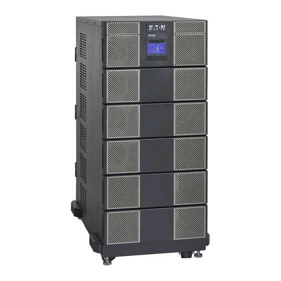
Introduction Physical Features The Eaton 9PXM UPS is available in eight or twelve-slot cabinet sizes. The cabinet front has a control panel and magnetic-latch front covers that provide access to the power modules and battery packs. Casters and leveling feet are installed on a caster tray for a floor-mounted UPS installation (see Figure 1). - Page 16 DB-9, USB ports and communication slots for network connectivity cards allow for remote monitoring of UPS operation. Slots for output receptacles installed by Eaton are available by removable knockout panels depending on the user’s requirements (see Figure 2).
-
Page 17: Battery String
Each battery module contains two battery packs that can be removed and installed separately from the battery slots in the chassis. A battery pack supplies 60VDC with five 12V batteries, each battery string in a 9PXM battery slot supplies 120VDC, with 10 batteries (see Figure 4). Battery Packs (2) Figure 4. -
Page 18: Uninterruptible Power Module
Uninterruptible Power Modules (UPM) The eight-slot 9PXM chassis can accommodate a maximum of four power modules and the twelve-slot can contain up to six modules. Each 4kVA has a built in 5 Amp battery charger and is cooled by two cooling fans.(see Figure 5). -
Page 19: Ups Control Panel
Operation” on page 55 for control panel description and operation. Indicator Lights Screen Online mode 100% 100% 2.7k W 19min 3.0kVA 1EBM Efficiency: 94 % Power/Navigation Buttons Figure 6. UPS Control Panel Eaton 9PXM UPS (4-20 kVA) User’s Guide P-164000669—Rev 05... - Page 20 Introduction This page intentionally left blank. Eaton 9PXM UPS (4-20 kVA) User’s Guide P-164000669—Rev 05...
-
Page 21: Installation Setup
External battery cabinets may be installed with bases tight against the UPS cabinet base and against each other. Location Requirements Install the Eaton 9PXM UPS as close as possible to the equipment or the load distribution panel it will protect. If a separate external battery cabinet (EBM) is installed, the battery cabinets must be adjacent to the Eaton 9PXM UPS. - Page 22 For ease of installation, determine if you have sufficient clearance at the rear of the UPS to complete the electrical connections before securing the UPS in its final position (see Chapter 4, “UPS Electrical Installation”) Eaton 9PXM UPS (4-20 kVA) User’s Guide P-164000669—Rev 05...
-
Page 23: Anchor Bracket Installation (Twelve-Slot Cabinet Only)
(Chapter 4, “UPS Electrical Installation”) The 12-slot Eaton 9PXM UPS cabinet is shipped with four anchor (stabilizer) brackets (Kit P-157002300). These brackets must be attached to the floor. Under all module-loading conditions, they act as a protective stop to prevent the cabinet from falling forward if it is unintentionally pushed. -
Page 24: Rack-Mount Installation
The Eaton 9PXM UPS and the battery cabinet are very heavy with power modules and battery strings installed. If installed, before moving the cabinets, remove the power modules and battery strings (see “Power Module and Battery String Installation”... - Page 25 Lower the leveling feet to stabilize the caster cart. Remove the rear bracket and screws. Using two people, slide the cabinet backwards to disengage it from the slot tabs. Lift the cabinet off of the caster cart. Eaton 9PXM UPS (4-20 kVA) User’s Guide P-164000669—Rev 05...
- Page 26 Screws Rack Mount Ears Figure 13. Securing the UPS in the Rack If you are installing an optional EBM cabinet P-103002494, refer to Chapter 5, “Battery Cabinet Installation” on page 39. Eaton 9PXM UPS (4-20 kVA) User’s Guide P-164000669—Rev 05...
-
Page 27: Ups With Bypass Electrical Installation
UPS with Bypass Electrical Installation The Eaton 9PXM UPS input power is hardwired through a conduit to either a main power source circuit breaker or to an optional bypass switch. It is recommended that you install an Eaton® Bypass Power Module (BPM) to enable power transfer during maintenance or UPS downtime. -
Page 28: Circuit Breaker Input Current Ratings
NOTE 2 To accommodate the feature of easy system expandability, it is recommended that initial installation of the Eaton 9PXM UPS contains wiring to support the maximum capacity of the UPS cabinet of 20kVA for 12-slot and 16-kVA for 8-slot cabinets. -
Page 29: Bypass Module Installation
To install the UPS with an external bypass switch: Mount the bypass switch within sight of the UPS. If you do not have an Eaton bypass switch or the fuse box or panel is out of sight, you must install a separate disconnect switch next to the UPS. - Page 30 Confirm that the UPS is wired for the proper input voltage as shown in Figure 16, and that the proper power modules will be installed to produce the desired output voltage. Eaton 9PXM UPS (4-20 kVA) User’s Guide P-164000669—Rev 05...
-
Page 31: Ups Input Wiring
Secure the cables by screwing down the lug screws. d. Torque the screws holding all input and output power conductors to the values specified in Table 2 on page 16. Reinstall the AC and DC terminal covers. Eaton 9PXM UPS (4-20 kVA) User’s Guide P-164000669—Rev 05... -
Page 32: Ups Input And Output Terminals
Use the label on the top of the BPM access cover and Figure 18, and make the connections to the BPM terminal blocks. Tighten all connections as specified in Table 2 on page 16. Use copper wire that is the appropriate size for the current draw. Eaton 9PXM UPS (4-20 kVA) User’s Guide P-164000669—Rev 05... -
Page 33: Input Signal Wire Routing
Route the maintenance bypass signal wires in a conduit from the bypass module to the communication signal terminal (CN13) on the rear of the UPS (see Figure 19). Place the signal wires through the proper conduit or grommet to the terminal block in the BPM Eaton 9PXM UPS (4-20 kVA) User’s Guide P-164000669—Rev 05... -
Page 34: Ups Input Control Signal Wiring For Maintenance Bypass
After electrical installation is complete, you must also set the output settings menu (See Figure 53 on page 62) for the required output voltage as shown in the wiring configuration drawings (See Figure 20 on page 24). Eaton 9PXM UPS (4-20 kVA) User’s Guide P-164000669—Rev 05... -
Page 35: System Wiring Diagram
UPS output circuits shall be installed in dedicated conduit systems and not shared with other electrical circuits. NOTE 8 Use only Eaton-supplied power cables between the UPS and EBM(s) (PN:P-103003231). NOTE 9 CN3 and CN4 CAN cables ground separately to each cabinet chassis. -
Page 36: Wiring Diagram - Ups With External Bypass Switch (L1, L2, N)
UPS with Bypass Electrical Installation Figure 20. Wiring Diagram - UPS with External Bypass Switch (L1, L2, N) Eaton 9PXM UPS (4-20 kVA) User’s Guide P-164000669—Rev 05... -
Page 37: Bypass Overview
When the red button is pressed, the UPS front panel displays “Manual Bypass. ” To move the MBP switch handle from one position to another, the red button must be pressed WHILE the handle is being rotated. Otherwise, the switch will be damaged. Eaton 9PXM UPS (4-20 kVA) User’s Guide P-164000669—Rev 05... -
Page 38: Bypass Module Operation
Depress and HOLD red button Rotate switch to LINE position LINE MODE UTILITY LOAD INPUT OUTPUT FROM INPUT OUTPUT Figure 22. Bypass From UPS to LINE Eaton 9PXM UPS (4-20 kVA) User’s Guide P-164000669—Rev 05... -
Page 39: Lock-Out/Tag-Out
After the system has been placed into SERVICE mode, it must be returned to UPS state to resume normal operation. WARNING It is critical that the following steps are followed to ensure correct and safe operation. To turn the BPM to UPS mode: Eaton 9PXM UPS (4-20 kVA) User’s Guide P-164000669—Rev 05... -
Page 40: From Line To Ups
After turning the load position handle to the UPS position and releasing the red button, if the Eaton 9PXM UPS remains in Bypass mode, return the UPS to Normal mode using the following procedure for proper... - Page 41 Press ESC twice to return to the Status Menu. The UPS is now in Normal mode. NOTE To disconnect AC input power during maintenance or service, turn the bypass switch to the SERVICE position. Table 4 shows the bypass switch models available for the Eaton 9PXM UPS. Table 4. Bypass Switch Specifications Height Width...
- Page 42 UPS with Bypass Electrical Installation This page intentionally left blank. Eaton 9PXM UPS (4-20 kVA) User’s Guide P-164000669—Rev 05...
-
Page 43: Ups Electrical Installation
Table 5. Required Input Circuit Breaker Sizes (120/208 Vac or 120/240 Vac, 60 Hz) UPS Capacity Input Circuit Breaker Rating 4 kVA 8 kVA 12 kVA 16 kVA 100A 20 kVA 125A Eaton 9PXM UPS (4-20 kVA) User’s Guide P-164000669—Rev 05... -
Page 44: Ups Electrical Installation
Risk of electrical shock. CAUTION To prevent electrical shock or damage to the equipment, verify that the Eaton 9PXM UPS is OFF before you remove the terminal covers. The circuit breaker or disconnect switch must also be OFF at the AC input service panel. - Page 45 Confirm that the UPS is wired for the proper input voltage as shown in Figure 29, and that the proper power modules will be installed to produce the desired output voltage. Eaton 9PXM UPS (4-20 kVA) User’s Guide P-164000669—Rev 05...
-
Page 46: Ups Input Wiring
UPS output circuits must be installed in separate conduit systems and not shared with other electrical circuits. Lug Screws Ground Terminal Block AC Output Connections AC Terminal Blocks AC Input Connections Figure 30. UPS Input and Output Terminal Connections Eaton 9PXM UPS (4-20 kVA) User’s Guide P-164000669—Rev 05... - Page 47 10. After electrical installation is complete, you must also set the output settings menu at UPS startup (See Chapter 6, “UPS Startup” on page 45) for the required output voltage as shown in the wiring configuration drawings (See Figure 31 on page 37). Eaton 9PXM UPS (4-20 kVA) User’s Guide P-164000669—Rev 05...
-
Page 48: System Wiring Diagram
UPS output circuits shall be installed in dedicated conduit systems and not shared with other electrical circuits. NOTE 7 Use only Eaton-supplied power cables between the UPS and EBM (PN:P-103003231). NOTE 8 CN3 and CN4 CAN cables ground separately to each cabinet chassis. -
Page 49: Wiring Diagram - Ups With No External Bypass (L1, L2, N)
UPS Electrical Installation Figure 31. Wiring Diagram - UPS with No External Bypass (L1, L2, N) Eaton 9PXM UPS (4-20 kVA) User’s Guide P-164000669—Rev 05... - Page 50 UPS Electrical Installation This page intentionally left blank. Eaton 9PXM UPS (4-20 kVA) User’s Guide P-164000669—Rev 05...
-
Page 51: Battery Cabinet Installation
Chapter 2, “Rack-Mount Installation” on page 12). If not, proceed to the next step. Install the anchor brackets to the floor if applicable (see Chapter 2, “Anchor Bracket Installation (Twelve-Slot Cabinet Only)” Eaton 9PXM UPS (4-20 kVA) User’s Guide P-164000669—Rev 05... -
Page 52: Ups Connections
AC terminal cover on the EBM is required. Communication Ports Chassis Ground Wire UPS DC Terminal Cover DC Emergency Disconnect Switch EBM Terminal Covers Figure 32. UPS Connections Eaton 9PXM UPS (4-20 kVA) User’s Guide P-164000669—Rev 05... -
Page 53: Connecting The Ebm(S) To The Ups
EBM configuration option as follows: Option #1 120V/208V or 120V/240V Split-Phase Input = Super Charger Capable, UPS Communication Capable and Extended Run-Time Battery Support (see Figure 34). G L1 N L2 Figure 34. Split-Phase Input Eaton 9PXM UPS (4-20 kVA) User’s Guide P-164000669—Rev 05... -
Page 54: No Ac Input
Connect the AC ground cable into the ground lug and tighten the lug screw. Connect the EBM AC input cables to the AC supply and the DC output cables to the UPS (see Figure 36). Reinstall the AC and DC terminal covers. Eaton 9PXM UPS (4-20 kVA) User’s Guide P-164000669—Rev 05... -
Page 55: Ups Input Control Signal Wiring (For External Controls)
To previous (upstream) EBM CN4 CAN IN CAN OUT CAN IN CAN OUT EBM 2 EBM 1 (CN3) (CN4) (CN3) (CN4) Figure 38. UPS Input Control Signal Wiring (for External Controls) Eaton 9PXM UPS (4-20 kVA) User’s Guide P-164000669—Rev 05... -
Page 56: Chassis Ground Wires
1/2-turn. Pull the button OUT to close the switch and reconnect DC power. Turn the key back counter-clockwise, and remove the key (see Figure 40) Disconnect Switch Figure 40. EBM Emergency Disconnect Switch 5-44 Eaton 9PXM UPS (4-20 kVA) User’s Guide P-164000669—Rev 05... -
Page 57: Ups Startup
UPS is not connected to an AC supply. When AC input voltage is present, the Eaton 9PXM system can provide output voltage even though its batteries are disconnected. To confirm that there is no UPS output voltage, always disconnect all of the AC input sources and unplug all strings of internal batteries;... - Page 58 If you installed the optional battery cabinets (EBMs), install the battery strings using the same procedure as the UPS modules. If applicable, install the super charger in the lower left slot of the EBM (see Figure 42) Eaton 9PXM UPS (4-20 kVA) User’s Guide P-164000669—Rev 05...
- Page 59 UPS Startup Battery Battery Strings Strings Super Charger EBM Front View (Covers removed) Figure 42. EBM Battery Strings and Charger Replace the front covers and continue to “UPS Startup”. Eaton 9PXM UPS (4-20 kVA) User’s Guide P-164000669—Rev 05...
-
Page 60: Ups Startup
9. Turn on the equipment that is connected to the UPS. 10. If there is an external bypass switch, turn it to UPS. Otherwise, close the load distribution circuit breaker(s). Eaton 9PXM UPS (4-20 kVA) User’s Guide P-164000669—Rev 05... -
Page 61: Initial Startup Parameters
MM/ DD / YYYY US International 02 / 17 / 2017 03 : 05 pm / 05 / 2011 15 : 05 Select 'Register product' from the menu and register your product with Eaton. Menu Please register at: Setttings www.eaton.com/pq... - Page 62 100% 100% 2.7k W 19min 3.0kVA 1EBM Efficiency: 94 % On/Off NOTE These configuration parameters are accessible during normal UPS operation by pressing the Menu screen through the front panel display. Eaton 9PXM UPS (4-20 kVA) User’s Guide P-164000669—Rev 05...
-
Page 63: Operation
To operate the UPS: Verify the UPS startup procedure has been completed (see Chapter 6, “UPS Startup” on page 48) 2. The UPS control panel display illuminates and shows the EATON logo. See “Control Panel Operation” on page 55. Verify that the power-on symbol shows on the UPS status screen. -
Page 64: Battery Mode
Return of AC Input Power Following an outage, the UPS restarts automatically when AC input power returns (unless the auto restart function has been disabled) and the load is supplied again. Eaton 9PXM UPS (4-20 kVA) User’s Guide P-164000669—Rev 05... -
Page 65: Setting High Efficiency Mode
“Half Cycle” but can be changed to “Full cycle” . Configuring battery settings The following battery settings enable battery tests, alarms and enable auto mode and (see Figure 55 on page 64). Eaton 9PXM UPS (4-20 kVA) User’s Guide P-164000669—Rev 05... -
Page 66: Advanced Battery Management
To retrieve the Fault log through the display: Press any button to activate the menu options, then select Fault log (see Figure 60 on page 67). Scroll through the listed faults. Reset fault log if desired. Eaton 9PXM UPS (4-20 kVA) User’s Guide P-164000669—Rev 05... -
Page 67: Control Panel Operation
) to scroll through the menu structure. Press the Enter ( ) button to select an option. Press the ESC button to cancel or return to the previous menu (see Figure 44). Eaton 9PXM UPS (4-20 kVA) User’s Guide P-164000669—Rev 05... -
Page 68: Lcd Description
The LCD backlight automatically dims after 10 minutes of inactivity. Press any button to restore the screen. Operation status Online mode 100% 100% Load/equipment status 2.7kW 19min Battery status 3.0kVA 1EBM Efficiency: 94% Efficiency and load group information Figure 45. LCD Display Status Indicators Eaton 9PXM UPS (4-20 kVA) User’s Guide P-164000669—Rev 05... -
Page 69: Display Status Indicators
Use the two middle buttons ( ) to scroll through the menu screens then press the Enter ) button to select an option (see Figure 48 to Figure 62). Eaton 9PXM UPS (4-20 kVA) User’s Guide P-164000669—Rev 05... -
Page 70: Display Menu Screens
Fault Log Identification Registration Information The Menu screen is the main menu and shows the available sub-menus. Menu Measurements Control Setttings Event log Fault Log Identification Register product Figure 49. Menu Screen Eaton 9PXM UPS (4-20 kVA) User’s Guide P-164000669—Rev 05... -
Page 71: Measurements
Measurements Cumulat. power usage Press ESC for previous screen Total output Output/Efficiency *Output readings Battery Since: Average power usage for example only 01/01/2000 00:00 Cumulat. power usage Figure 50. Measurements Menu Eaton 9PXM UPS (4-20 kVA) User’s Guide P-164000669—Rev 05... -
Page 72: Control
Reset fault state Reset fault state Are you sure? Restore factory set Restore factory set Reset average power Reset average power Reset cumul. power Reset cumul. power Figure 51. Control Menu Eaton 9PXM UPS (4-20 kVA) User’s Guide P-164000669—Rev 05... -
Page 73: Local Settings
Mode: [Enabled][Disabled Audible alarm on battery][Always disabled] Enabled √ Enable or alwaysdisable the Disabled on battery buzzer if an alarm occurs. Always disabled Figure 52. Local Settings Menu Eaton 9PXM UPS (4-20 kVA) User’s Guide P-164000669—Rev 05... -
Page 74: In/Out Settings
12% Default disables Byp volt max limit transfer to Bypass if the measured bypass voltage level is above the nominal output voltage plus 12% Figure 53. In/Out Settings Menu Eaton 9PXM UPS (4-20 kVA) User’s Guide P-164000669—Rev 05... -
Page 75: On/Off Settings
400 W after defined duration. of 600 W 1000 W back-up time, if load is less 1500 W than set value 2000 W Default: Disabled [200W] Figure 54. On/Off Settings Menu Eaton 9PXM UPS (4-20 kVA) User’s Guide P-164000669—Rev 05... -
Page 76: Battery Settings Menu
Warranty void if No prevents battery from deep discharge by adapting end of back-up time voltage threshold. √ Warranty void if set to No. Default Value: [Yes] Figure 55. Battery Settings Menu Eaton 9PXM UPS (4-20 kVA) User’s Guide P-164000669—Rev 05... -
Page 77: Input Signals
User Password Enable User Password settings Force Bypass Select Input Signals [Enabled] [Disabled] Disabled [Normally open] Normally open Maintain Bypass [Enabled] [Disabled] Disabled [Normally open] Normally open Figure 56. Input Signals Menu Eaton 9PXM UPS (4-20 kVA) User’s Guide P-164000669—Rev 05... -
Page 78: Comm Settings
Minislot 1 reset Comm Settings Remote command Minislot 2 reset Shutdown command Are you sure? [Yes] [No] Battery notice delay Minislot 1 reset Minislot 2 reset Figure 57. Comm Settings Menu Eaton 9PXM UPS (4-20 kVA) User’s Guide P-164000669—Rev 05... -
Page 79: User Password Settings
Event log Fault Log Identification Fault Log Fault Log Register product Reset fault list Fault list Are you sure? Reset fault list Reent list Reset event list Figure 60. Fault Log Menu Eaton 9PXM UPS (4-20 kVA) User’s Guide P-164000669—Rev 05... -
Page 80: Identification
COM card IPv6 Maintenance bypass: COM card MAC Detected accessories Identification Figure 61. Menu Registration Information The Register product screen provides directions to register the product with Eaton. Menu Please register at: Setttings www.eaton.com/pq Event log Type Fault Log Eaton_9PXM... -
Page 81: Communication
Chapter 8 Communication Eaton offers several methods of communicating with your Eaton 9PXM system in addition to the front panel display: ® Intelligent Power Manager (IPM) Power Management Software Optional Interface Kits Communication ports Dedicated Input Signals DB-9 Communication Port... -
Page 82: Ebm Communication Ports
Eaton 9PXM system shutdown. Opening this connection creates an immediate shutdown of the Eaton 9PXM UPS output. Maintenance Bypass: The signal from an external bypass switch, to isolate the Eaton 9PXM system for maintenance purposes, tells the UPS to go into Internal Bypass mode. -
Page 83: Db-9 Communication Port
Communication DB-9 Communication Port Table 7 explains the functions of the pins on the Eaton 9PXM DB-9 communication port. This port is on the Eaton 9PXM UPS rear panel, as shown in Figure 63. Table 7. DB-9 Port Signals Function... -
Page 84: Pxgx Ups Card
Eaton UPS and any relay-connected computer as well as a variety of industrial applications. The Relay Card-MS is compatible with all Eaton UPSs that have a Minislot. -
Page 85: Maintenance
Storage Temperature Store the Eaton 9PXM battery packs (in the UPS or external battery cabinet) at –20 to +40°C (–4 to +104°F). Batteries will have a longer shelf life if they are kept below +25°C (+77°F). The Eaton 9PXM UPS or battery cabinet without batteries may be stored at –40 to +60°C (–40 to +140°F). -
Page 86: Power Module Replacement
Screw Figure 65. Battery Replacement Power Module Replacement The Eaton 9PXM easy replace feature lets you replace a power module without disconnecting the load or damaging the UPS. NOTE The UPS may switch to internal Bypass mode if the remaining power modules are insufficient to supply the required power. -
Page 87: Power Module Replacement
Insert the replacement power module by sliding it carefully into the cabinet. 5. Tighten the captive screws to the UPS cabinet. Replace the front cover. Front Covers Power Module Captive Screws Figure 66. Power Module Replacement Eaton 9PXM UPS (4-20 kVA) User’s Guide P-164000669—Rev 05... -
Page 88: Ups Firmware Upgrade
Maintenance UPS Firmware Upgrade This procedure is intended for the firmware upgrade of the 9PXM UPS model. Please follow these steps carefully to ensure complete success of the firmware upgrade on this model UPS. The firmware can be upgraded via RS232 connection or USB connection. If a USB connection is used, Option 2 from the Main menu, will be a required step in this process. - Page 89 Maintenance Figure 68. Create Unzip Folder Use ‘eaton’ as the password when prompted during the extraction process. Figure 69. Enter Extraction Password After the extraction is complete the following files will be visible in the new folder that was created: Eaton 9PXM UPS (4-20 kVA) User’s Guide...
-
Page 90: Launch The Firmware Upgrade Tool
On your computer choose option 2 from the Main menu to install USB drivers Select the driver that is suited for the Windows PC used for the upgrade from the secondary menu. Eaton 9PXM UPS (4-20 kVA) User’s Guide P-164000669—Rev 05... -
Page 91: Ups Csb Firmware Upgrade
The tool is ready to proceed with firmware upgrades. UPS CSB firmware Upgrade (Do not use bypass mode) Place the UPS in standby mode Choose option 3 from the Main menu and confirm to run CSB firmware upgrade. Eaton 9PXM UPS (4-20 kVA) User’s Guide P-164000669—Rev 05... - Page 92 Figure 74. CSB Upgrade Selection A new window will appear as the upgrade begins. Figure 75. Upgrade Initialization Once communication is established the window will display the connection type, connection port, and speed. Eaton 9PXM UPS (4-20 kVA) User’s Guide P-164000669—Rev 05...
- Page 93 6. The application will then set the UPS into Bootloader mode. If this is completed successfully, the current firmware is erased in preparation for the new firmware to be uploaded. At this point, the application will begin to upload the new firmware. Eaton 9PXM UPS (4-20 kVA) User’s Guide P-164000669—Rev 05...
-
Page 94: Ups Csb Firmware Installation Complete
CSB/logs folder. A successful upgrade will look like the image below: Figure 79. UPS CSB Firmware Installation Complete 10. Before attempting to run the application again fully power-cycle the UPS. Eaton 9PXM UPS (4-20 kVA) User’s Guide P-164000669—Rev 05... -
Page 95: Upm Or Ebm/Supercharger Firmware Upgrade
RS232 (usually COM1) USB to RS232 (assigned COM port) USB (assigned Virtual COM port) Figure 81. Firmware Comm Port Selection Press the Enter key to begin. 5. The following screen will appear: Eaton 9PXM UPS (4-20 kVA) User’s Guide P-164000669—Rev 05... -
Page 96: Flash Data
6. The flash programming will begin. Figure 83. Flash Data The programming address will increment as the UPM is being programmed Figure 84. Programming Address When finished, the following screen will appear: Eaton 9PXM UPS (4-20 kVA) User’s Guide P-164000669—Rev 05... - Page 97 Maintenance Figure 85. Flash Data Complete Press any key to continue. 10. The main menu will reappear. UPM - EBM/Supercharger firmware upgrade complete. Eaton 9PXM UPS (4-20 kVA) User’s Guide P-164000669—Rev 05...
- Page 98 Maintenance This page intentionally left blank. Eaton 9PXM UPS (4-20 kVA) User’s Guide P-164000669—Rev 05...
-
Page 99: Specifications
Chapter 10 Specifications This section provides the following specifications for the Eaton 9PXM models: Nominal Electrical Input and Output Combined UPM Power Ratings Circuit Breakers Environmental and Safety Battery Output Run Times Weights and Dimensions Nominal Electrical Input and Output Table 8. -
Page 100: Circuit Breakers
The air around the UPS must be clean and free of dust, corrosive chemicals, and other contaminants. The Eaton 9PXM UPS uses internal fans to circulate the air for cooling. The air must be free to circulate around the UPS and battery cabinet(s). Do not operate the UPS in a sealed room Ventilation or container. -
Page 101: Battery Ratings
(8.5") (26.5 lb) Super Charger 29.2 cm 68.6 cm 38.1 cm 12.5 kg 15.2 cm 58.4 cm 21.6 cm 10.2 kg (11.5") (27.5") (15") (27.5 lb) (6") (23") (8.5") (22.5 lb) Eaton 9PXM UPS (4-20 kVA) User’s Guide P-164000669—Rev 05... -
Page 102: Output Receptacles
(6") (9 lb) (5") (5") (3") (8 lb) Output Receptacles Figure 86 shows the types of compatible output receptacles. L14-30 IEC309 5-20 L6-20 L6-30 L5-30 L5-20 Figure 86. Compatible Output Receptacles Eaton 9PXM UPS (4-20 kVA) User’s Guide P-164000669—Rev 05... -
Page 103: Troubleshooting
Chapter 11 Troubleshooting Troubleshooting The Eaton 9PXM is designed for durable, automatic operation and also alert you whenever potential operating problems may occur. Usually the alarms shown by the control panel do not mean that the output power is affected. Instead, they are preventive alarms intended to alert the user. -
Page 104: Silencing The Alarm
Press the ESC (Escape) button on the front panel display to mute the alarm. Check the alarm condition and perform the applicable action to resolve the condition. If the alarm status changes, the alarm beeps again, overriding the previous alarm muting. Eaton 9PXM UPS (4-20 kVA) User’s Guide P-164000669—Rev 05... -
Page 105: Frequently Asked Questions
Physically install or remove battery packs as described in “Battery Replacement” on page 73. If of batteries? not using a 9PXM EBM, record the capacity of external battery strings (in all external battery cabinets) by going to menu Figure 50 on page 59 Add/delete one or more power Physically install or remove power modules as described in “Power Module Replacement”... -
Page 106: Service And Support
A replacement or repair unit will be shipped, freight prepaid for all warrantied units. NOTE For critical applications, immediate replacement may be available. Call the Help Desk for the dealer or distributor nearest you. Eaton 9PXM UPS (4-20 kVA) User’s Guide P-164000669—Rev 05... -
Page 107: Warranty
LIMITED WARRANTY: This limited warranty (this “Warranty”) applies only to the original End-user (the “End-user”) of any 9PXM product purchased on or after June 1, 2004, and cannot be transferred. This Warranty applies even in the event that the Product is initially sold by Company for resale to an End-user. - Page 108 Any costs for replacement equipment, installation, materials, freight charges, travel expenses or labor of Company representatives outside the terms of this Warranty will be borne by the End-user. Eaton 9PXM UPS (4-20 kVA) User’s Guide P-164000669—Rev 05...
- Page 109 LIMITED GUARANTY: This load protection guaranty (this “Guaranty”) applies only to the original End-user (the “End-user”) of any Eaton 9PXM Product and cannot be transferred. This Guaranty applies even in the event that the Product is initially sold by Company for resale to an End-user.
- Page 110 TO MAKE A CLAIM: In the USA, call the Customer Reliability Center 7x24 at 800-356-5737 . Outside of the USA, contact your local Eaton product sales or service representative for units purchased from those countries, or call the Customer Reliability Center in the USA at 919-845-3683 for units purchased in the USA that were shipped overseas.
- Page 112 * 164000669* P-164000669 R05...
Need help?
Do you have a question about the 9PXM and is the answer not in the manual?
Questions and answers