Table of Contents
Advertisement
Quick Links
Advertisement
Table of Contents

Subscribe to Our Youtube Channel
Related Manuals for Eaton 9PXM


Summary of Contents for Eaton 9PXM
- Page 1 Eaton 9PXM UPS Eaton 9PXM UPS 4–20kVA Users Guide p/n: P-164000669 Revision 09...
- Page 2 ERIFLEX and FLEXIBAR are registered trademark of Erico International Corporation. All other trademarks are property of their respective companies. All other trademarks are property of their respective companies. ©Copyright 2020 Eaton, Raleigh, NC, USA. All rights reserved. No part of this document may be reproduced in any way without the express written approval of Eaton.
- Page 3 (WEEE) in the trash. For proper disposal, contact your local recycling/ reuse or hazardous waste center. IMPORTANT To ensure you have the most up-to-date content and information for this product, please review the latest manual revision on our website, https://www.eaton.com/9PXM...
-
Page 5: Table Of Contents
6.1 UPS Startup ............................61 6.2 UPS Startup Without an External Bypass Switch ..................... 63 6.3 Startup for Units Installed with an Eaton BPM Bypass Switch ................64 6.4 Startup for Units installed with a BPE Type Switch................... 66 6.5 Initial Startup Parameters ........................... 67 7 7 O O p p e e r r a a t t i i o o n n . - Page 6 Table of Contents 7.3 UPS Shutdown ............................71 7.4 Operating Modes ............................. 71 7.4.1 Online Mode............................71 7.4.2 Battery Mode............................. 72 7.4.3 Low Battery Warning........................... 72 7.4.4 Bypass Mode............................. 72 7.5 Return of AC Input Power........................... 73 7.6 Configuring Bypass Settings ........................73 7.7 Configuring Battery Settings ........................
- Page 7 Table of Contents 10.4 Environmental and Safety ........................102 10.5 Battery Ratings............................. 103 10.6 Output Run Times..........................103 10.7 Weights and Dimensions........................103 10.8 Output Receptacles..........................104 10.9 Receptacle Circuit Breaker Ratings ......................105 1 1 1 1 T T r r o o u u b b l l e e s s h h o o o o t t i i n n g g ....................................................... . 1 1 0 0 7 7 11.1 Troubleshooting............................
- Page 8 Table of Contents viii 4–20kVA Users Guide P-164000669 4–20kVA Users Guide P-164000669—Rev 09...
- Page 9 L L i i s s t t o o f f F F i i g g u u r r e e s s Figure 1. Eight and Twelve-Slot Cabinets ( Front View) ..................3 Figure 2. Twelve-Slot Rear View Access ......................4 Figure 3.
- Page 10 List of Figures Figure 40. Standard EBM to UPS Connections....................47 Figure 41. EBM Emergency Disconnect Switch ....................48 Figure 42. Super Charger Location ......................... 50 Figure 43. EBM to UPS Connections ......................51 Figure 44. Battery Cable Assembly Installation ....................52 Figure 45.
- Page 11 List of Figures Figure 81. Compatible Output Receptacles ....................104 Figure 82. Event Log Menu ........................107 4–20kVA Users Guide P-164000669 4–20kVA Users Guide P-164000669—Rev 09...
- Page 12 List of Figures 4–20kVA Users Guide P-164000669 4–20kVA Users Guide P-164000669—Rev 09...
- Page 13 L L i i s s t t o o f f T T a a b b l l e e s s Table 1. Recommended Breaker Sizes ......................18 Table 2. Recommended Wire Sizes ......................18 Table 3. Bypass Switch Positions .........................
- Page 14 List of Tables 4–20kVA Users Guide P-164000669 4–20kVA Users Guide P-164000669—Rev 09...
-
Page 15: 8 C C O O M M M M U U N N I I C C A A T T I I O O N
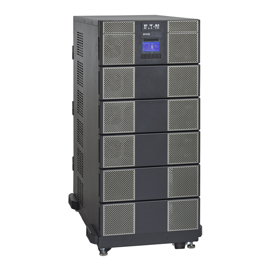
• The 9PXM is a modular UPS with a power range of 4kVA to 20kVA. Each Power Module is rated for up to 4kVA. The 20kVA (N+1) Split-Phase model chassis will have twelve slots, two per row. All of the twelve slots can accommodate two battery modules per slot. -
Page 16: Safety Warnings
NO instale en los módulos de potencia del sistema más de siete módulos de potencia y/o de cargadores opcionales de baterías. • Los módulos de baterías a utilizarse en el sistema Eaton 9PXM son del modelo P-103002954. Cada módulo de batería pesa 15 kg (33 lb). Levante y mueva con cuidado los módulos de baterías. •... -
Page 17: Physical Features
P P h h y y s s i i c c a a l l F F e e a a t t u u r r e e s s The Eaton 9PXM UPS is available in eight or twelve-slot cabinet sizes. The cabinet front has a control panel and magnetic-latch front covers that provide access to the power modules and battery modules. - Page 18 Physical Features Figure 2. Twelve-Slot Rear View Access DB-9 Port Communication Ports USB Port Communication Card Slots Main AC Output Hardwired Knockout Recepticle Panels AC Input Hardwired EBM Input Connection (Twelve slot chassis shown. Eight-slot similar) Power Modules UPS power modules (UPMs) are installed in the left hand slots of the UPS behind the front covers. Battery slots consist of two battery modules each and can be used in both the right or left hand slots.
- Page 19 Shown. Battery Modules As a UPS, the eight-slot 9PXM chassis can accommodate a maximum of seven two-battery slots and the twelve-slot can contain up to eleven two-battery slots. Each two-battery slot contains two battery modules that can be removed and installed separately from the battery slots in the chassis. A battery module supplies...
- Page 20 Each 4kVA has a built in 5 amp battery charger and is cooled by two cooling fans. (see Figure 5 ). One power module (UPM) is able to fully charge five 9PXM battery strings ( 10 9PXM battery modules). NOTE You must install one 9PXM battery string (2 battery modules) in the main UPS chassis for every power module present or the UPS will sound an “Not Enough Battery”...
-
Page 21: 9 M M A A I I N N T T E E N N A A N N C C E
The UPS can contain a minimum of one (optional) super charger while the “Connected”external battery module option can accommodate one in the lower left slot. One super charger is able to fully charge (22) 9PXM battery strings or (44) individual battery modules. Control Panel The UPS control panel has a graphical LCD screen, light indicators and function buttons. - Page 22 Physical Features 4–20kVA Users Guide P-164000669 4–20kVA Users Guide P-164000669—Rev 09...
-
Page 23: Equipment Clearances
L L o o c c a a t t i i o o n n R R e e q q u u i i r r e e m m e e n n t t s s Install the Eaton 9PXM UPS as close as possible to the equipment or the load distribution panel it will protect. - Page 24 UPS Setup Move the UPS shipping pallet close to the desired location. If installed, remove the straps and bracket bolts that attach the UPS to the pallet (see Figure 7 If you are rack-mounting the UPS, proceed to “ 2.6 Rack-Mount Installation”...
- Page 25 See or 4.2 UPS Electrical Installation The Eaton 9PXM UPS cabinet is shipped with four anchor (stabilizer) brackets (Kit P-157002300). These brackets must be attached to the floor. Under all module-loading conditions, they act as a protective stop to prevent the cabinet from falling forward if it is unintentionally pushed.
-
Page 26: Rack-Mount Installation
The Eaton 9PXM UPS and the battery cabinet are very heavy with power modules and two battery modules per slot installed. If installed, before moving the cabinets, remove the power modules and battery two battery modules per slot (see “9.1 Routine Maintenance... - Page 27 Rack-Mount Installation NOTE 1 The UPS cabinets may be installed in an EIA-standard 48.3 cm (19") equipment rack. An optional rack-mounting kit (P-157002204), containing brackets and required hardware, is available. NOTE 2 This procedure is also applicable to the P-103002494 12-slot external battery module (EBM).
- Page 28 Rack-Mount Installation Figure 11. Rack Tray Location UPS Rack Rails UPS Rack Rails (Front) Rail Backs Screw Washer Rail Tray Remove the cabinet from the castor cart as follows ( see Figure 12 Lower the leveling feet to stabilize the castor cart. Remove the rear bracket and screws.
- Page 29 Rack-Mount Installation Figure 12. Remove Cabinet from Castor Tray UPS Cabinet Note: Attach appropriate lifting device and use at least two people to lift the UPS cabinet Slot Tabs Caster Tray Rear Bracket Carefully slide the UPS from the caster tray onto the rail tray in the equipment rack until the rack-mount ears of the cabinet are almost flush with the front vertical rails of the rack.
- Page 30 Rack-Mount Installation Figure 13. Securing the UPS in the Rack Equipment Rack Screws Rails Rail Tray Screws Rack Mount Ears If you are installing an optional EBM cabinet refer to, “5.1 Standard Battery Cabinet Installation” or “ 5.2 Connected Battery Cabinet Option”.
- Page 31 I I n n s s t t a a l l l l a a t t i i o o n n o o f f t t h h e e U U P P S S w w i i t t h h a a n n E E x x t t e e r r n n a a l l B B y y p p a a s s s s S S w w i i t t c c h h The Eaton 9PXM UPS input power is hardwired through a conduit to either a main power source circuit breaker or to an optional bypass switch.
-
Page 32: Circuit Breaker Input Ratings
UPS cabinet of 20kVA for 12-slot and 16-kVA for 8-slot cabinets. NOTE 3 The 9PXM is limited to an input current of 125A. In the event an additional charging module has been employed in conjunction with the maximum allotted number of power modules, no additional input ampacity will be required. -
Page 33: Ups Connections
To install the UPS with an external bypass switch: Mount the bypass switch within sight of the UPS. If you do not have an Eaton bypass switch or the fuse box or panel is out of sight, you must install a separate disconnect switch next to the UPS. - Page 34 UPS Connections Figure 16. UPS AC Power Terminal Access AC Output Terminals Terminal Cover AC Input Terminals Terminal Cover At the AC Input terminal, make sure to wire the UPS for the proper input voltage as shown in Figure 17 Split-phase power modules provide a 2-phase output which can be configured as output voltages: 110/110 for 220, 120/120 for 240, 120/120 for 208, or 127/127 for 220 Vac, as selected through the front panel display.
- Page 35 UPS Connections Figure 17. Split-Phase Power Modules Split-Phase Power Modules (3-wire plus ground input) (2 PEN) 110/220, 120/208, 120/240, 127/220 Vac NOTE UPS output circuits must be installed in separate conduit systems and not shared with other electrical circuits. Make the UPS input and output connections to the terminal blocks on the rear panel (see Figure 18 Insert the L1, N and L2 cable ends into the applicable terminal slots on the terminal block.
- Page 36 UPS Connections Figure 18. UPS Input and Output Terminals Lug Screws Ground L1 L1 Terminal Block AC Output Connections AC Terminal Blocks AC Input Connections Route the power cables to the BPM and install conduit adapters to the BPM bottom plate. Use the label on the top of the BPM access cover and Figure 19, and make the connections to the BPM...
- Page 37 UPS Connections Figure 19. Bypass Switch Wiring Label and Terminal Blocks Upper BPM Terminal Block AC FROM AC TO UPS OUTPUT UPS INPUT Lower BPM Terminal Block AC LINE INPUT AC TO LOADS CABLES FROM UPS AND AC INPUT/OUTPUT THROUGH BPM BOTTOM ACESS PLATE BPE Terminal Block After installing bypass switch wiring, torque the screws holding all input and output power conductors to...
-
Page 38: Bpm Signal Input Wire Routing
BPM Signal Input Wire Routing 3 3 . . 4 4 B B P P M M S S i i g g n n a a l l I I n n p p u u t t W W i i r r e e R R o o u u t t i i n n g g CAUTION The auxiliary contacts must be wired to the BPM from the UPS for proper functionality. - Page 39 Attach the supplied cable connectors to the ends of the input wires. For BPE connections as shown in : Connect up the 4 wires from the BPE to the 9PXM per the attached drawing and using the 3 pin connector (see Figure 21 Figure 21.
-
Page 40: 3.5 System Wiring Diagrams
BPM Signal Input Wire Routing Navigate the 9PXM LCD to the forced and maintain bypass settings Input signals menu in the 9PXM user guide (see Figure 23 Set both Forced Bypass and Maintain Bypass settings to Enabled and Normally open (see Figure 23 Figure 23. - Page 41 UPS output circuits shall be installed in dedicated conduit systems and not shared with other electrical circuits. NOTE 8 Use only Eaton-supplied power cables between the UPS and EBM(s) (PN:P-103003231). NOTE 9 CN3 and CN4 CAN cables ground separately to each cabinet chassis.
- Page 42 System Wiring Diagrams Figure 24. Wiring Diagram- UPS with External Bypass Switch (BPM) (L1, L2, N) 4–20kVA Users Guide P-164000669 4–20kVA Users Guide P-164000669—Rev 09...
- Page 43 System Wiring Diagrams Figure 25. Wiring Diagram- UPS with External Bypass Switch (BPE) (L1, L2, N) 4–20kVA Users Guide P-164000669 4–20kVA Users Guide P-164000669—Rev 09...
-
Page 44: Bypass Overview
Bypass Overview 3 3 . . 6 6 B B y y p p a a s s s s O O v v e e r r v v i i e e w w The BPM has three operating positions (see Table 3 ). -
Page 45: No Break Transfer From Ups Mode To Service Mode
No Break Transfer from UPS Mode to Service Mode NOTE In the UPS or LINE position, AC input power is still connected to the input terminals inside the UPS. Table 3. Bypass Switch Positions Switch Position Description LINE When the switch is in the LINE position, utility power is directly connected to the critical load and the output of the UPS is disconnected. -
Page 46: Lock-Out/Tag-Out
Lock-out/Tag-out Figure 27. Bypass From UPS to LINE Depress and HOLD red button Rotate switch to LINE position LINE MODE LOAD UTILITY INPUT OUTPUT FROM INPUT OUTPUT Turn the switch from LINE to SERVICE (see Figure 28 ). The critical load is fed directly from utility and the UPS is now completely disconnected from AC power. -
Page 47: No Break Transfer From Service Bypass To Ups Mode
No Break Transfer from Service Bypass to UPS Mode Figure 29. LOTO Feature Depress and HOLD red bar Remove Lock and Install lock and tag Tag to reset in any opening at LOTO position the base of switch Install a lock and tag in any opening at the base of the switch according to LOTO procedures. Remove the lock and tag to reset the LOTO position. - Page 48 After turning the load position handle to the UPS position and releasing the red button, if the Eaton 9PXM UPS remains in Bypass mode, return the UPS to Normal mode using the following procedure for proper operation: 4–20kVA Users Guide P-164000669 4–20kVA Users Guide P-164000669—Rev 09...
- Page 49 NOTE 2 To disconnect AC input power during maintenance or service, turn the bypass switch to the SERVICE position. NOTE 3 Table 4 shows the bypass switch models available for the Eaton 9PXM UPS. Table 4. BPM Dimensions Height Width Depth...
- Page 50 No Break Transfer from Service Bypass to UPS Mode 4–20kVA Users Guide P-164000669 4–20kVA Users Guide P-164000669—Rev 09...
- Page 51 C C h h a a p p t t e e r r 4 4 U U P P S S E E l l e e c c t t r r i i c c a a l l I I n n s s t t a a l l l l a a t t i i o o n n 4 4 .
-
Page 52: Ups Input Current Ratings
To accommodate the feature of easy system expendability, it is recommended that initial installation of the Eaton 9PXM UPS contains wiring to support the maximum capacity of the UPS cabinet : 20kVA for 12–slot cabinets and 16kVA for 8 slot chassis. -
Page 53: Ups Electrical Installation
CAUTION To prevent electrical shock or damage to the equipment, verify that the Eaton 9PXM UPS is OFF before you remove the terminal covers. The circuit breaker or disconnect switch must also be OFF at the AC input service panel. - Page 54 UPS Electrical Installation Figure 33. UPS Power Terminals AC Output Terminals Terminal Cover AC Input Terminals Terminal Cover At the AC Input terminal, make sure to wire the UPS for the proper input voltage as shown in Figure 34 Split-phase power modules provide a 2-phase output which can be configured as output voltages: 110/110 for 220, 120/120 for 240, 120/120 for 208, or 127/127 for 220 Vac, as selected through the front panel display (“7.15 Display Menu Screens...
- Page 55 UPS Electrical Installation Figure 34. Split-Phase Power Modules Split-Phase Power Modules (3-wire plus ground input) (2 PEN) 110/220, 120/208, 120/240, 127/220 Vac NOTE UPS output circuits must be installed in separate conduit systems and not shared with other electrical circuits. 4–20kVA Users Guide P-164000669 4–20kVA Users Guide P-164000669—Rev 09...
- Page 56 UPS Electrical Installation Figure 35. UPS Input and Output Terminal Connections Lug Screws Ground L1 L1 Terminal Block AC Output Connections AC Terminal Blocks AC Input Connections Make the UPS input and output connections to the terminal blocks on the rear panel (see Figure 35 NOTE UPS output circuits must be installed in separate conduit systems and not shared with...
-
Page 57: System Wiring Diagram
UPS output circuits shall be installed in dedicated conduit systems and not shared with other electrical circuits. NOTE 7 Use only Eaton-supplied power cables between the UPS and EBM(s) (PN:P-103003231). NOTE 8 CN3 and CN4 CAN cables ground separately to each cabinet chassis. - Page 58 System Wiring Diagram Figure 36. UPS with No External Bypass (L1,L2,N) Figure 35. Wiring Diagram - UPS with No External Bypass (L1, L2, N) 4–20kVA Users Guide P-164000669 4–20kVA Users Guide P-164000669—Rev 09...
- Page 59 C C h h a a p p t t e e r r 5 5 B B a a t t t t e e r r y y C C a a b b i i n n e e t t I I n n s s t t a a l l l l a a t t i i o o n n 5 5 .
-
Page 60: Standard Battery Cabinet Installation
Standard Battery Cabinet Installation NOTE 1 The external battery cabinets are the same dimensions as the UPS cabinets. Refer to the ” 2.1 Preparing for Installation ” section for unpacking and cabinet setup. NOTE 2 If you are installing multiple EBM(s) upstream to the UPS, repeat the setup as described in this section. -
Page 61: Figure 40. Standard Ebm To Ups Connections
Standard Battery Cabinet Installation Figure 39. Battery Cable Installation For Standard EBM(s) Screws Cover Terminal Block DC+ DC- DC- DC+ DC input cables from upstream EBM (if installed) To UPS NOTE Torque the screws holding all input and output power conductors to the values specified Table 2 Connect the EBM DC Cables to the applicable terminals by removing and reinstalling the screws onto the terminal blocks. -
Page 62: Connected Battery Cabinet Option
Connected Battery Cabinet Option NOTE DC input cables only required if EBM(s) are installed upstream. Close the DC emergency disconnect switch button on the back of each EBM. Insert the switch key supplied with the cabinet into the button and turn clockwise 1/2-turn. Pull the button OUT to close the switch and reconnect DC power. - Page 63 Connected Battery Cabinet Option CAUTION • Before connecting an external battery cabinet to the UPS cabinet or to another external battery cabinet, verify that all AC input power is removed from the UPS. Open the input service circuit breaker or turn the external bypass switch to the SERVICE position.
-
Page 64: Figure 42. Super Charger Location
Connected Battery Cabinet Option Figure 42. Super Charger Location EBM Front EBM Back Communication Ports Battery Battery Modules Modules DC Emergency Disconnect Switch Super Charger UPS DC UPS AC Terminal Terminal Covers Covers EBM Front View (Covers removed) Prepare the EBM Cabinet NOTE 1 The external battery cabinets are the same dimensions as the UPS cabinets. -
Page 65: Figure 43. Ebm To Ups Connections
Connected Battery Cabinet Option CAUTION Make sure all AC power is removed from the UPS. Observe all electrical safety precautions. Push in the EBM DC emergency disconnect switch on the rear EBM panel and turn the switch lockout key (see Figure 48 NOTE The UPS and EBM AC/DC terminal covers are shipped in the UPS and EBM accessory... -
Page 66: Figure 44. Battery Cable Assembly Installation
Connected Battery Cabinet Option Figure 44. Battery Cable Assembly Installation Screws Screws Cover Ground Terminal Block Terminal Block DC+ DC- DC- DC+ G L1 N L2 DC input cables from To Dedicated 30 Amp upstream EBM Circuit. (if installed) To UPS NOTE Torque the screws holding all input and output power conductors to the values specified Table 2... -
Page 67: Figure 46. Single Phase Input
Connected Battery Cabinet Option 120VAC Single Phase Input UPS Communication Capable and Extended Run-Time Battery Support (see Figure 46 NOTE A 5–15 line cord is included in the EBM accessory kit. Only to be used with this wiring option. Figure 46. Single Phase Input G L1 N Option #3 120V/208V or 120V/240V Split-Phase Input = Super Charger Capable, UPS Communication Capable and... -
Page 68: Figure 47. Split Phase Input
Connected Battery Cabinet Option Figure 47. Split Phase Input G L1 N L2 Connect the AC ground cable into the ground lug and tighten the lug screw. Connect the EBM AC input cables to the dedicated 30 amp AC circuit and the DC output cables to the UPS (See Figure 43). -
Page 69: Figure 48. Ebm To Ups Connections
Connected Battery Cabinet Option Figure 48. EBM to UPS Connections To UPS Signal Input Port CN4 To upstream EBM CN4 (if installed) To AC supply for EBM Terminal UPS/EBM super Blocks Terminal charger Block (if installed) From previous (if installed) On the upper rear panels, connect the input signal cables from the EBM CN4 to the UPS input signal port CN4 using the supplied cables. -
Page 70: Figure 49. Ups Input Control Signal Wiring (For External Controls)
Connected Battery Cabinet Option Figure 49. UPS Input Control Signal Wiring (For External Controls) External CAN (CN7) (CN4) ROO and On Generator To EBM(s) (CN6) Signal cables and connectors (supplied) To previous (upstream) EBM CN4 CAN IN CAN OUT CAN IN CAN OUT EBM 2 EBM 1... -
Page 71: Figure 50. Can Communication Wires Ebm To Ebm
Connected Battery Cabinet Option Figure 50. CAN Communication Wires EBM to EBM EBM 2 EBM 1 Secure Green and Yellow CAN cable ground Secure Green and Yellow CAN cable ground Green Terminal Jumper in Last EBM wire to the chassis wire to the chassis NOT FOR CUSTOMER USE NOT FOR CUSTOMER USE... -
Page 72: Figure 51. Can Communication Wires Ups To Ebm
Connected Battery Cabinet Option Figure 51. CAN Communication Wires UPS to EBM EBM 1 NOT FOR CUSTOMER USE CAN IN CAN OUT LAST EBM RS-232 JUMPER Green Terminal Jumper in Last EBM Grey EBM CAN Communication Cable Secure Green and Yellow CAN Secure Green and Yellow CAN cable ground wire to the chassis cable ground wire to the chassis... -
Page 73: Figure 52. Ebm Emergency Disconnect Switch
Connected Battery Cabinet Option Figure 52. EBM Emergency Disconnect Switch Disconnect Switch IMPORTANT For connected battery options #2 and #3 the UPS is set to automatically detect the number of battery strings in the external battery cabinet. If option #1 is used continue to 6.5 Initial Startup Parameters to set the number of external battery strings on the UPS LCD for calculating the runtime. - Page 74 Connected Battery Cabinet Option 4–20kVA Users Guide P-164000669 4–20kVA Users Guide P-164000669—Rev 09...
- Page 75 This UPS contains its own energy source (batteries). The output receptacles may carry hazardous voltage even when the UPS is not connected to an AC supply. When AC input voltage is present, the Eaton 9PXM system can provide output voltage even though its batteries are disconnected. To confirm that there is no UPS output voltage, always disconnect all of the AC input sources and unplug all two battery modules per slot of internal batteries;...
-
Page 76: Ups Startup
UPS Startup • Slide the lower battery module fully into the slot until it contacts the connections in the rear of the slot. • Repeat the procedure with the upper battery module. • Install the retaining bracket and tighten the captive screw with a Phillips screwdriver. Figure 53. -
Page 77: Ups Startup Without An External Bypass Switch
Replace the front covers and continue to “ 6.2 UPS Startup Without an External Bypass Switch, 6.3 Startup for Units Installed with an Eaton BPM Bypass Switch 6.4 Startup for Units installed with a BPE Type Switch ”. 6 6 . . 2 2... -
Page 78: Figure 55. Communication Ports
Startup for Units Installed with an Eaton BPM Bypass Switch Figure 55. Communication Ports DB9 Port (CN17) USB Port (CN12) When starting the UPS, apply input power to the UPS by closing the service circuit breaker: • If external battery cabinets are installed, close the DC emergency disconnect switch button on the back of each external battery cabinet. - Page 79 Startup for Units Installed with an Eaton BPM Bypass Switch Remove the six screws in the bypass switch front cover and remove the cover to gain access to the terminal block for voltage measurements. If external battery cabinets are installed, close the DC emergency disconnect switch button on the back of each external battery cabinet.
- Page 80 Startup for Units installed with a BPE Type Switch 15. The UPS front panel display automatically turns on whenever input power is present and at least one power module is installed. Set up the initial operating parameters through the front panel display (see “ 6.5 Initial Startup Parameters ”...
-
Page 81: Initial Startup Parameters
Initial Startup Parameters Determine what type of bypass switch you are using: If the bypass switch is a Break-Before-Make type, skip this step and proceed to Step 13. If the bypass switch is a Make-Before-Break type, verify that the AC voltages from the UPS and the AC line input are in phase. - Page 82 The first time the UPS is turned on, you must set or verify certain operating parameters before placing the UPS into operation. To set these initial configuration parameters: After the Eaton® logo screen appears, select the desired language for the display. Use the and buttons to scroll between English, French, and Spanish. Enter your selection by pressing the button.
- Page 83 10 min 10 . 1 kV If you have a “Standard” Eaton 9PXM battery cabinet or a “Connected” No AC battery cabinet option installed navigate to the battery settings menu and set the number of external battery strings that you have installed.
- Page 84 Initial Startup Parameters 4–20kVA Users Guide P-164000669 4–20kVA Users Guide P-164000669—Rev 09...
-
Page 85: Ups Shutdown
7 7 . . 4 4 . . 1 1 O O n n l l i i n n e e M M o o d d e e The Eaton 9PXM front panel indicates the UPS status through the UPS indicators, see page 11. -
Page 86: Operating Modes
Operating Modes 7 7 . . 4 4 . . 2 2 B B a a t t t t e e r r y y M M o o d d e e Battery Mode When the UPS is operating during a power outage, the alarm beeps once every ten seconds and the indicator illuminates solid. -
Page 87: Return Of Ac Input Power
Return of AC Input Power NOTE 1 NOTE Load imbalance between UPMs is <5% NOTE 2 NOTE The UPS shuts down after a specified delay for overload conditions listed above. 7 7 . . 5 5 R R e e t t u u r r n n o o f f A A C C I I n n p p u u t t P P o o w w e e r r Following an outage, the UPS restarts automatically when AC input power returns (unless the auto restart function has been disabled) and the load is supplied again. -
Page 88: Advanced Battery Management
Retrieving the Event Log 7 7 . . 7 7 . . 1 1 A A d d v v a a n n c c e e d d B B a a t t t t e e r r y y M M a a n n a a g g e e m m e e n n t t Advanced Battery Management (ABM) extends the life of the battery by shutting off the charger for 28 days per ABM cycle and therefore reduces grid corrosion in the battery caused by trickle charging over long periods of time. -
Page 89: Display Functions
Display Functions Figure 56. UPS Control Panel Online mode Fault indicator (green) indicator (red) Bypass mode Battery mode indicator (orange) indicator (orange) Screen Online mode 100% 100% 2.7k W 19min 3.0kVA 1EBM Efficiency: 94 % Escape Down Enter On/Off button 7 7 . -
Page 90: Lcd Description
LCD Description Indicator Status Description Orange The UPS is on Bypass mode. Bypass The UPS has an active alarm or fault. See Chapter 11, “Troubleshooting” for additional information. 7 7 . . 1 1 2 2 L L C C D D D D e e s s c c r r i i p p t t i i o o n n After five minutes of inactivity, the LCD displays the screen saver. -
Page 91: Changing Parameter Settings
Changing Parameter Settings Figure 58. Display Status Indicators Indicator Status Description Standby Mode The UPS is Off, waiting for startup command Equipment is not powered until button is from user. The indicator flashes pressed. Green LED blinking when UPS is continually. -
Page 92: Figure 59. Start Screen
Format : www.eaton.com Françias 120 V International 127 V Type Español 23/05/2020 15 :05 Eaton...9PXM Start Screen Status Screen The status screen shows the status of the installed units. Figure 60. Status Screen Menu Press to start 100 % 100 % 10 . -
Page 93: Figure 61. Menu Screen
Display Menu Screens Figure 61. Menu Screen Menu Measurements √ Control Settings Event Log Identification Register Product Measurements The Measurements screen shows the measurements of the installed units. 4–20kVA Users Guide P-164000669 4–20kVA Users Guide P-164000669—Rev 09... -
Page 94: Figure 62. Measurements Menu
Display Menu Screens Figure 62. Measurements Menu Total Load Measurements Total Load 0.0A Load Phase 1 (N-L1) Load Phase 2 (N-L2) Input 0.00pf Bypass Measurements Load Phase 1 (N-L1) Total Load 0.0A Load Phase 1 (N-L1) Load Phase 2 (N-L2) Input 0.00pf Bypass... -
Page 95: Figure 63. Control Menu
Display Menu Screens Control The Control menu provides bypass control and reset of some fault and factory settings. Figure 63. Control Menu Control Control Control Control Go to bypass Go to bypass Go to bypass Go to bypass Go to bypass Alarm Go to bypass Start battery test... -
Page 96: Figure 64. Local Setting Menu
Display Menu Screens Local Settings The Settings menus allow the user to modify UPS settings. Figure 64. Local Setting Menu Language [English] [Français] English √ [Espanol] Menus, status, notices and alarms, UPS fault, Françias Event Log data and Español settings are in all supported languages. -
Page 97: Figure 65. In/Out Settings Menu
Display Menu Screens In/Out Settings The In/Out Settings menus allows control of input and output limits. Figure 65. In/Out Settings Menu Output voltage 110 V √ [110V] [120V][127V] 120 V Default:[120V][127V] 127 V High Efficiency mode [Enabled] [Disabled] Power the output from Disabled √... -
Page 98: Figure 66. On/Off Settings Menu
Display Menu Screens On/Off Settings The On/Off Settings Menu enables/disables selected automatic restart and shutdown functions. Figure 66. On/Off Settings Menu [Enabled] [Disabled] [Timer] [10s] … [180s] Forced reboot When mains recover during a shutdown sequence: If set to Enabled, shutdown Disabled √... -
Page 99: Figure 67. Battery Settings Menu
Display Menu Screens Battery Settings The Battery Settings Menu provides control of battery tests, warnings and modes. Figure 67. Battery Settings Menu ABM On Off Advanced Battery Mode Enabled √ [Enabled] [Disabled] Disabled In ABM cycling mode: Auto battery test [No test] [Every ABM cycle] In constant charge mode: Enabled... -
Page 100: Figure 68. Input Signals Menu
Display Menu Screens Input Signals The Input Signals Menu enables/disables power features for the UPS. Figure 68. Input Signals Menu Emergency Power Off Disabled [Enabled] [Disabled] Enabled √ Remote On/Off Disabled [Enabled] [Disabled] [Normally open] Normally Open Settings Local Settings Input Signals On Generator In/Out settings... -
Page 101: Figure 69. Comm Settings Menu
Display Menu Screens Comm Settings The Comm Settings Menu enables/disables some selected control signal features. Figure 69. Comm Settings Menu Minislot 1 remote off Disabled Default Value: [Enabled] Enabled √ Minislot 2 remote off Disabled Default Value: [Enabled] Enabled √ Remote command [Enabled] [Disabled] If Enabled, shutdown or restart... -
Page 102: Figure 70. Password Menus
Display Menu Screens User Password Settings Figure 70. Password Menus Settings User Password Enable On/Off settings Battery settings Input signals Disabled √ Enabled Comm settings User password enable User password settings Settings Settings Settings On/Off settings Go to bypass Go to bypass Protected access Protected access Battery settings... -
Page 103: Figure 73. Identification Menu
Display Menu Screens Identification The Identification screen shows the product type and installed accessories. Figure 73. Identification Menu Identification Type Product type/model Part/Serial number Eaton_9PXM UPS/NMC firmware Model CSB/EBM firmware 4KVA Com card IPv4 Identification Part number Product type/model 9PXM_4kVA Part/Serial number UPS/NMC firmware Serial number... -
Page 104: Figure 74. Register Product Menu
Display Menu Screens Registration Section The Register product screen provides directions to register the product with Eaton. Figure 74. Register Product Menu Date / Time Date / Time Date / Time Menu Date / Time Please register at: Settings Format :... -
Page 105: Intelligent Power Manager
I I n n t t e e l l l l i i g g e e n n t t P P o o w w e e r r M M a a n n a a g g e e r r Eaton offers several methods of communicating with your Eaton 9PXM system in addition to the front panel display: •... -
Page 106: Dedicated Input Signals
Eaton 9PXM system shutdown. EPO Connections In the 9PXM UPS, EPO can be configured either as Normally Open (NO) or Normally Closed (NC) contacts. Connector CN7 on the rear panel of the UPS is used for EPO. 4–20kVA Users Guide P-164000669 4–20kVA Users Guide P-164000669—Rev 09... -
Page 107: Figure 77. Normally Open Connections
The REPO switch must be a latching type switch not tied to any other cicuits. Maintenance Bypass: The signal from an external bypass switch, to isolate the Eaton 9PXM system for maintenance purposes, tells the UPS to go into Internal Bypass mode. -
Page 108: Db-9 Communication Port
D D B B - - 9 9 C C o o m m m m u u n n i i c c a a t t i i o o n n P P o o r r t t Table 7 explains the functions of the pins on the Eaton 9PXM DB-9 communication port. This port is on the... -
Page 109: Communication Slots
Eaton UPS and any relay-connected computer as well as a variety of industrial applications. The Relay Card-MS is compatible with all Eaton UPSs that have a Minislot. - Page 110 Communication Slots 4–20kVA Users Guide P-164000669 4–20kVA Users Guide P-164000669—Rev 09...
-
Page 111: Routine Maintenance
S S t t o o r r a a g g e e T T e e m m p p e e r r a a t t u u r r e e Store the Eaton 9PXM battery modules (in the UPS or external battery cabinet) at –20 to +40°C (–4 to +104°F). -
Page 112: Power Module Replacement
P P o o w w e e r r M M o o d d u u l l e e R R e e p p l l a a c c e e m m e e n n t t The Eaton 9PXM easy replace feature lets you replace a power module without disconnecting the load or damaging the UPS. -
Page 113: Ups Firmware Upgrade
To ensure you have the most up-to-date content and information for this product, please review the latest manual revision on our website, https://www.eaton.com/9PXM FW upgrade program and instructions are located at the following web link: https://www.eaton.com/9PXM. 4–20kVA Users Guide P-164000669 4–20kVA Users Guide P-164000669—Rev 09... - Page 114 UPS Firmware Upgrade 4–20kVA Users Guide P-164000669 4–20kVA Users Guide P-164000669—Rev 09...
-
Page 115: Nominal Electrical Input And Output
1 1 0 0 . . 1 1 N N o o m m i i n n a a l l E E l l e e c c t t r r i i c c a a l l I I n n p p u u t t a a n n d d O O u u t t p p u u t t This section provides the following specifications for the Eaton 9PXM models: •... -
Page 116: Circuit Breakers
Ventilation The air around the UPS must be clean and free of dust, corrosive chemicals, and other contaminants. The Eaton 9PXM UPS uses internal fans to circulate the air for cooling. The air must be free to circulate around the UPS and battery cabinet(s). - Page 117 Battery Ratings Table 10. Environmental and Safety (Continued) Surge Suppression EN 61000-4-5 Safety Conformance CSA C22.2, No. 107.3; UL1778 5th Edition Agency Markings NOM, UL, CUL, FCC EMC (Class A) EN 62040-2, FCC Part 15, EN 61000-4-2 level 3 Criteria B, EN 61000-4-3 level 3 Criteria A, EN 61000-4-4, 61000-4-5, 61000-4-6, 61000-4-8 1 1 0 0 .
- Page 118 Output Receptacles Table 12. Weights and Dimensions (Continued) 88 kg 88.9 cm 88.9 cm 64.1 cm 63.5 cm 87.6 cm 44.5 cm 54.4 kg 70.8 kg (156 8 Slot EBM (35") (35") (25.5") (25") (34.5") (17.5") (120 lb) (194 lb) 15 kg 16.5 cm 64.8 cm...
- Page 119 Receptacle Circuit Breaker Ratings 1 1 0 0 . . 9 9 R R e e c c e e p p t t a a c c l l e e C C i i r r c c u u i i t t B B r r e e a a k k e e r r R R a a t t i i n n g g s s Table 13.
- Page 120 Receptacle Circuit Breaker Ratings 4–20kVA Users Guide P-164000669 4–20kVA Users Guide P-164000669—Rev 09...
- Page 121 1 1 1 1 . . 1 1 T T r r o o u u b b l l e e s s h h o o o o t t i i n n g g The Eaton 9PXM is designed for durable, automatic operation and also alert you whenever potential operating problems may occur.
- Page 122 Troubleshooting and number of Extended Battery Modules (EBMs), the "Battery Low" warning may occur before the batteries reaches low capacity. LED is On 1 beep every 3 seconds No Battery The batteries are disconnected. Verify that all batteries are properly connected.
- Page 123 Troubleshooting UPS Overtemperature The UPS internal temperature is too high If the UPS transferred to Bypass mode, or a fan has failed. At the warning level, the UPS will return to normal operation the UPS generates the alarm but remains when the temperature drops 5°C below in the current operating state.
- Page 124 Physically install or remove battery modules as described in “ Add/delete one or more slots of batteries? 9.4 Battery Replacement” . If not using a 9PXM EBM, record the capacity of external battery slots (in all external battery cabinets) by going to menu Figure Physically install or remove power modules as described in “...
- Page 125 Service and Support • Date of failure or problem • Symptoms of failure or problem • Customer return address and contact information If repair is required, you will be given a Returned Material Authorization (RMA) Number. This number must appear on the outside of the package and on the Bill Of Lading (if applicable). Use the original packaging or request packaging from the Help Desk or distributor.
- Page 126 Service and Support 4–20kVA Users Guide P-164000669 4–20kVA Users Guide P-164000669—Rev 09...
- Page 127 LIMITED WARRANTY: This limited warranty (this “Warranty”) applies only to the original end-user (the “End- user”) of any 9PXM, 9170 and FERRUPS 4.3–1 kVA Products (individually and collectively, the “Product”) purchased on or after June 1, 2004, and cannot be transferred. This Warranty applies even in the event that the Product is initially sold by Company for resale to an End-user.8...
- Page 128 WARRANTY Two-Year Limited Warranty (Cont.) UPS MODELS: 9PXM, 9170+ AND FERRUPS 4.3–18 kVA (USA AND CANADA)(Cont.) This Warranty is not valid if the Product's serial numbers have been removed or are illegible. Any Warranted Items repaired or replaced pursuant to this Warranty will be warranted for the remaining portion of the original Warranty subject to all the terms thereof.
- Page 129 Two-Year Limited Warranty COSTS NOT RELATED TOWARRANTY:The End-user shall be invoiced for, and shall pay for, all services not expressly provided for by the terms of this Warranty, including without limitation, site calls involving an inspection that determines no corrective maintenance is required. Any costs for replacement equipment, installation, materials, freight charges, travel expenses or labor of Company representatives outside the terms of this Warranty will be borne by the End-user.
- Page 130 P-16400066909 P-164000669 09...
Need help?
Do you have a question about the 9PXM and is the answer not in the manual?
Questions and answers