Table of Contents
Advertisement
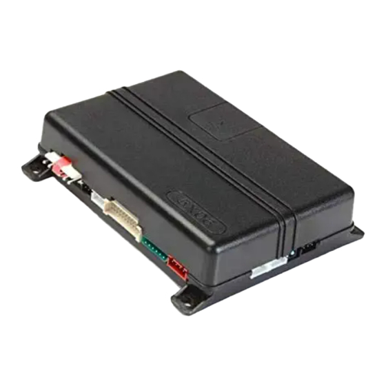
Responder HD, LCD, LED
and 1-way Models:
5906, 5706, 5806 and 5606
Security and Remote Start
Installation Guide
This product is intended for installation by a professional
installer only! Attempts to install this product by a person
other than a trained professional may result in severe
damage to a vehicle's electrical system and components.
© 2016 Directed, Vista, CA
N5x06 2016-02
Advertisement
Table of Contents

Subscribe to Our Youtube Channel
Related Manuals for Directed 5906


Summary of Contents for Directed 5906
- Page 1 Responder HD, LCD, LED and 1-way Models: 5906, 5706, 5806 and 5606 Security and Remote Start Installation Guide This product is intended for installation by a professional installer only! Attempts to install this product by a person other than a trained professional may result in severe damage to a vehicle’s electrical system and components.
- Page 2 FailSafe®, Learn Routine™, NPC®, Nuisance Prevention Circuitry®, Revenger®, Silent Mode™, Soft Chirp®, Stinger®, Valet®, and Warn Away® are all Trademarks or Registered Trademarks of Directed®. Bitwriter (P/N ® 998U) requires chip version 2.7 or newer to program this unit. Bitwriters with a date code of 6A or older require an IC upgrade (P/N 998M).
-
Page 3: Table Of Contents
Remote Start, White 10-pin heavy gauge connector ..............7 Door Lock, 3-pin connector ......................7 D2D Harness, Red 4-pin connector ....................7 Bitwriter/Directed SmartStart Harness, Black 3-pin connector............7 Wire Descriptions ........................... 7 Main Harness, 6-pin connector ....................7 Auxiliary/Shutdown/Trigger Harness, 24-pin connector ..............9 Remote Start Heavy Gauge Harness, 10-pin connector .............. -
Page 4: Warning! Safety First
This testing should be performed by an authorized Directed dealer in accordance with the Safety Check outlined in this product installation guide. If the vehicle starts in gear, cease remote start operation immediately and consult with the user to fix the problem immediately. -
Page 5: Wiring Diagram
Note: Sensor ports 1 and 2 cannot support constant power and ground connections for 508D due to current limitations. When installing a 508D use alternate location for constant power and ground connections. See Tech Tip #1924: Adding external sensor(s) to a Directed system. © 2016 Directed. All rights reserved. -
Page 6: Wiring Connections
** Connect this wire to the (-) parking brake wire in the vehicle (see Owners Guide for manual transmission procedure). Important: NEVER connect 200mA low current outputs directly to a motor or high current device WITHOUT a relay. © 2016 Directed. All rights reserved. -
Page 7: Remote Start, White 10-Pin Heavy Gauge Connector
D2D Harness, Red 4-pin connector BLUE D2D - TX BLACK (-) GROUND GREEN D2d - RX (+) 12V Bitwriter/Directed SmartStart Harness, Black 3-pin connector (+) 12V ORANGE ESP 2 - RX/TX BLACK (+) 12V Wire Descriptions Main Harness, 6-pin connector Red: (+) 12V CONSTANT INPUT This wire supplies power to the unit’s micro-controller. - Page 8 Place the fuse in the correct position for the desired polarity Note: Any parking lights circuit which draws 10 amperes or more must use P/N 8617 (or a standard automotive SPDT relay) to drive the circuit in the vehicle. © 2016 Directed. All rights reserved.
-
Page 9: Auxiliary/Shutdown/Trigger Harness, 24-Pin Connector
This (-) 200mA output is used for controlling any Auxiliary function such as fuel door release or a window module. This output can be programmed for different applications. (see the AUX 1 options in Feature Menus for more detail). © 2016 Directed. All rights reserved. - Page 10 Switch Type in Feature Menus for more detail). Note: This wire can only monitor one door when used in a Normally Closed door trigger circuit. To interface with more than one N/C door trigger use an interface or Tech Tip #1921. © 2016 Directed. All rights reserved.
-
Page 11: Remote Start Heavy Gauge Harness, 10-Pin Connector
Remote Start Heavy Gauge Harness, 10-pin connector Empty Pin: No Connection Red/Black: (+) 12V INPUT This wire connects to a (+) 12V source and is the power feed for the onboard Accessory and Starter relays. © 2016 Directed. All rights reserved. -
Page 12: Door Lock, 3-Pin Connector
Although this connector is not populated with a wire in this position, the pin on the unit supplies a low current (+) 12V output and is utilized when using a P/N 451 Door Lock Relay Module. © 2016 Directed. All rights reserved. -
Page 13: Adjusting The Doubleguard Shock Sensor
Important: After successfully learning Virtual Tach, a small minority of vehicle starters may over or under crank during remote start. The Bitwriter can be used fine tune the starter output time in 50 millisecond increments to compensate for such an occurrence. © 2016 Directed. All rights reserved. -
Page 14: Learning Hardwired Or Data Tach (Not Needed With Virtual Tach)
Startup Diagnostics: If the vehicle fails to activate the remote start, the remote start module will notify you via 2-way remote control and the remote start module will flash the parking lights on the vehicle to notify you of what caused the no-start situation. © 2016 Directed. All rights reserved. -
Page 15: Programming System Features
The Learn Routine exits if any of the following occurs: • The open door is closed. • The ignition is turned ON. • There is no activity for 30 seconds. • The Control Center button is pressed too many times. © 2016 Directed. All rights reserved. -
Page 16: Feature Menus
1. On: the Panic output can be activated at any time . 2. Ign. OFF Only: the Panic output can be activated only when the ignition is OFF. 3. OFF: the Panic output is defeated. © 2016 Directed. All rights reserved. - Page 17 1. Single: full trigger activation of only one sensor is required to fully trigger the alarm. 2. Double: full trigger activation of two sensors within a ten second period is required to fully trigger the alarm. © 2016 Directed. All rights reserved.
-
Page 18: Menu 2 - Convenience
Link to Disarm Link to Arm/ Link to Remote Disarm Start Only AUX/Trunk Output Type Validity 2nd Unlock AUX channels with the 1-button remote can only be accessed with channel linking to unlock or remote start. © 2016 Directed. All rights reserved. - Page 19 5. OFF: the output will not activate for a remote control command, use this option when the AUX command controls an external device such as a garage door module. 6. 2nd Unlock: the output will operate as 2nd Unlock and will not activate for remote control commands. © 2016 Directed. All rights reserved.
- Page 20 15. AUX 4 Output Type • Refer to AUX 1 Output Type descriptions. 16. AUX 4 Linking • Refer to AUX 1 Linking descriptions. 17. AUX/Trunk Output Type • Refer to AUX 1 Output Type descriptions. © 2016 Directed. All rights reserved.
-
Page 21: Menu 3 - Remote Start
12/24/60 minutes: sets engine runtime during normal remote start operations. 5. Activation Pulse Count • 1/ 2 pulses: sets the number of remote control commands received or Activation Input required to activate and de-activate remote start. © 2016 Directed. All rights reserved. - Page 22 2. OFF: the high current starter relay will not be activated during remote start, no anti-grind protection is available. Note: The Anti-grind feature works in conjunction with the Orange GWA wire in the main 6-pin connector. © 2016 Directed. All rights reserved.
- Page 23 2. ON: the Door lock and output will arm/lock the vehicle during after the crank output from the remote start and once again after the remote start shuts OFF. © 2016 Directed. All rights reserved.
-
Page 24: Bitwriter - Only Options
The Bitwriter plugs into the black 3-pin plug on the system. The black 3-pin port will also be utilized by the optional Smartstart module when applicable. © 2016 Directed. All rights reserved. -
Page 25: Pairing A Remote Control
Note: Both the remote control and the vehicle need to be setup to pair a remote to the system and the remote must be set to the desired Car1 or Car2 mode. (see Owners Manual for more details about selecting vehicles). © 2016 Directed. All rights reserved. - Page 26 • The Control Center LED begins flashing in a single flash pattern and the siren will chirp once to confirm the system is in pairing mode. Now release the Control Center Button. • © 2016 Directed. All rights reserved.
- Page 27 To exit Pairing Mode on the system: Turn OFF the ignition. • • Close the open door. • Wait 60 seconds for the system to automatically exit. • The siren will sound to confirm exiting. © 2016 Directed. All rights reserved.
-
Page 28: Basic Remote Functions
4. Once you have selected the function step, press the Control Center button once more and hold it. The LED flashes and the siren chirps to confirm the selected functional step. Do not release the Control Center button. © 2016 Directed. All rights reserved. -
Page 29: Long Term Event History
1. Is passive arming programmed ON? 2. Are the door inputs connected? Is the 24-pin harness Blue wire connected to the door trigger wire in the vehicle? Either the 24-pin harness Green or Violet wire should be used instead. © 2016 Directed. All rights reserved. -
Page 30: Troubleshooting: Remote Start
Voltage sense will not work on some vehicles. 3. Is the remote start in tach mode? If so has the tach been programmed to the system? 4. Check diagnostics. Sometimes a shutdown will become active during cranking or just after cranking. © 2016 Directed. All rights reserved. - Page 31 OFF or after a certain amount of time, with these vehicles unfortunately there is no workaround. • The E-brake wire connected to the parking brake input of the system has a poor ground. Clean the contacts on the switch or replace the switch. © 2016 Directed. All rights reserved.
Need help?
Do you have a question about the 5906 and is the answer not in the manual?
Questions and answers