Table of Contents

Related Manuals for Mountain Models HiperBipe


Summary of Contents for Mountain Models HiperBipe
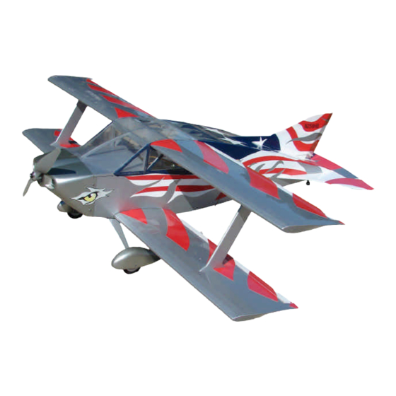
- Page 1 HiperBipe Scale Aerobatic Electric Model HiperBipe Specifications Wingspan: 35.38 in. Length: 31.3 in. Wing Area: 358 sq. in. Weight (Ready to Fly): 20 to 24 oz. Wing Loading: 8.0 – 9.6 oz. / sq. ft. Version 1.0, September 23, 2011...
-
Page 2: Warranty
Mountain Models online at www.MountainModels.com Thank you for purchasing the Mountain Models HiperBipe. Our kit is a 1/8 scale model of the Sorrel SNS-7 Hiperbipe. Our model is a parkflyer model designed to give you a great scale model that is very unique, aerobatic, and easy to build. -
Page 3: Before You Begin
Before You Begin Check to make sure that all of your parts are there and in good shape. Parts List Number Description of Part in Kit Bundled Parts Laser Cut Parts (37 Sheets!) These instructions of course! Metal (on the back of the wood bundle) 0.032”... -
Page 4: Finishing Materials You Will Need
• Sanding bar and 320-400 grit sandpaper • Covering Iron Finishing Materials You Will Need • Covering material (SoLite, 2 rolls) • Covering Trim (SolarTrim) Electronics You Will Need • 4 channel radio minimum • 4 to 6 channel mini receiver (Berg 4L, Berg 7, or Spektrum 6110e) •... -
Page 5: Fuselage Assembly
FUSELAGE ASSEMBLY: 1. Slide the " Lt. Ply F3 (with text facing FORWARD) into the Lt. Ply crutch, F1 (with text facing UP), rotating it into place. Do NOT glue it yet. 2. Press the crutch into the 1/16" plywood F4, with the text of F4 facing FORWARD. - Page 6 6. Press the " Lt Ply F2 onto the crutch assembly. (Do NOT glue yet) 7. Insert 4-40 T-Nuts into the bottom (dirty) side of " Lt Ply F5. Make sure they are flush with the part, using a hammer, if needed. 8.
-
Page 7: Left And Right
12. Press the " Ply F21a into " Balsa F21. Make a LEFT and RIGHT, assembling them side by side, as shown. Making sure they are pressed fully together. 13. Glue the " balsa F21b onto F21a, using thick CA, being sure that they are lined 14. - Page 8 15. Insert the crutch assembly into F21 with the plywood doubler facing to the OUTSIDE. It helps to lay the doubler on the table and press the crutch into F21. Then, pick it up and press the doubler fully onto the crutch.
- Page 9 17. Press the other fuselage doubler onto the crutch, once again with the plywood facing to the OUTSIDE. 18. Yes, you really do get to use the glue bottle in earnest! Glue all of the joints in the assembly with thin CA, AFTER making sure all parts are fully pressed together, and that F9 is at a slight...
- Page 10 19. Glue the " Balsa F15 parts together, using thin CA. 20. Press F15 in place in the fuselage crutch, as shown. The small holes in F15 (for hatch screws) goes to the back of the fuselage. Do NOT glue it in place yet. 21.
- Page 11 22. Press the " Balsa F16 dashboard in place in the fuselage assembly. Secure with thin CA. 23. Glue the " Balsa fuselage sides together, consisting of F23, F23a, F23b, F23c, and F23d. The parts shown below marked with X's have the dirty side of the wood facing up, for best parts fit.
- Page 12 25. Glue the fuselage parts, F18 ( " Balsa), F19 ( " Balsa), and F12 ( " Balsa) together with thin CA, as shown above. 26. Glue a fuselage side onto the RIGHT side of the fuselage crutch assembly with thick CA. Make sure the fuselage side is pressed completely onto the crutch assembly.
- Page 13 25. Press F13 and F11onto F12. The text on F11/F12 should be facing FORWARD and the text on F12 should be UP. Do NOT glue them yet. 26. Press the F11/F12/F13 assembly into the right fuselage side. Do NOT glue yet. 27.
- Page 14 30. Slide the Landing Gear mount in place, with LG1 facing the FRONT. Glue in place with thin CA. 31. Glue F20 and F18 in place on the fuselage. ONLY glue in F20 at this time, with thin CA.
- Page 15 32. Press F19 into place on the fuselage. Make sure all joints are fully inserted. Press the back of the fuselage down so it is sitting FLAT on the fuselage bottom and secure the fuselage top and bottom with thin CA. 33.
- Page 16 35. Slide the hatch in place, and secure in place with 2 of the #2x " screws. Do NOT overtighten the screws. Take out the screws, remove the hatch, and reinforce the threaded holes with thin CA. 36. Glue the "...
- Page 17 40. Glue the " Balsa FH8 in place, as shown. 41. Glue the " Balsa FH5 in place, lined up with the front of FH2 and centered on FH8. 42. Glue the " Balsa FH4 parts together, using thin CA. 43.
- Page 18 PUSHROD HOUSINGS PUSHROD HOUSINGS BOTTOM VIEW 47. Glue the pushrod housings in place, as shown above. Leave about " of pushrod in front of the former. 48. Trim the pushrod housing flush with the fuselage top and bottom, where they exit. 49.
- Page 19 50. Glue all " Balsa Stab and Elevator parts together with thin CA, as shown in the images above. 51. Sand all tail parts lightly with 320 Grit sandpaper. TOP OF ELEVATOR 52. Sand a bevel in the elevator and rudder, as shown.
- Page 20 53. Press " Lt Ply MM2 and MM3 onto the " Plywood MM4, but do NOT glue yet. 54. Press the " Lt Ply MM1in place, as shown. 55. Make sure parts are fully inserted and secure with thin CA. 56.
- Page 21 58. Glue the " Balsa LG2 to the " Balsa LG1 with thick CA, lining up the edges. Repeat to make a LEFT and RIGHT side, as shown. Cut out the center 'tabs' in LG2 so the landing gear wire can fit in there. 59.
- Page 22 63. Bend the " wire to form the main landing gear. TIP: Use a good wire bender, like the K&S or DuBro wire benders to make this an easy job! 64. Bend the tail gear wire from 0.032" wire. Attach the tailwheel by sliding the wheen onto the wire and then bending the wire up 90 degrees to keep the wheen on.
- Page 36 COVERING: 1. Cover your airplane with SoLite. Do NOT use heavier coverings, such as MonoKote, UltraCote, etc. If you do, you can warp and damage the structure, and will need a lot of nose weight to balance your airplane. 2. Refer to the instructions that came with your SoLite on how to cover and in what order to cover your airplane components.
- Page 38 4. Assemble the wheels and wheel pants to the landing gear wire, as shown below. The wire starts through the wheel pant, through an " Lt Ply spacer, through the wheel, through another " Lt Ply spacer, and out the other side of the wheel pant.
- Page 39 7. Press the main landing gear wire into the landing gear mount in the fuselage. Press the landing gear retainer into the slot to retain the main landing gear wire. We do not glue the landing gear wire or the retainer in place, so it can be removed, if need be later on.
- Page 40 10. Slide the Horizontal Stab into the fuselage slot, centered. Press the Vertical Stab and Skid through the fuselage and into the slots in the Stab. Make any adjustments (like sanding lightly) to make sure they fit properly. 11. When happy with the fits, glue the Stab, Vertical, and Skid in place, making sure that the Vertical Fin is at a 90 degree angle to the...
- Page 41 12. Hinge the Rudder to the Vertical Fin and the Elevator to the Stab, using Hinge Tape, as shown in the drawings. Make sure that they move freely in each direction. If they do not, remove the tape and try again. TAPE Elevator at full deflection.
- Page 42 15. Install the motor as shown below, with the included 4-40 x " bolts. 16. Install a DuBro EZ Servo Connector onto one end of the long servo arm of your servo. 17. With your servos centered (power up your radio to double check), install the servo arms, as shown below.
-
Page 46: First Flights
We know you'll enjoy the HiperBipe as much as we have. We would like to hear any feedback you have on any of our models, as we are always looking for improvements based on our valuable customer feedback.
Need help?
Do you have a question about the HiperBipe and is the answer not in the manual?
Questions and answers