Advertisement
Quick Links
1
www.MountainModels.com
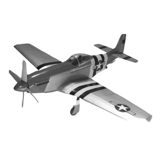
P-51 Mustang
1/12 Scale Electric Park Flyer
Wingspan: 37", Wing Area: 254 sq. in., Weight: 15 to 19.5 oz
Instructions Version 1.61, July 27, 2011
LIABILITY RELEASE
In that Mountain Models has no control over the final assembly or material used for final assembly, no
liability shall be assumed or accepted for any damage resulting from the use by the user of the final
user-assembled product. By the act of using the user-assembled product, the user accepts all resulting
liability. If the buyer is not prepared to accept the liability associated with the use of this product, the
buyer is advised to return the kit immediately in new and unused condition.
THIS PRODUCT IS NOT INTENDED FOR CHILDREN 12 YEARS OF AGE OR YOUNGER
Warning: This product may contain chemicals known to the State of California to cause cancer or birth
defects or other reproductive harm
Copyright 2005-2011 Mountain Models
Advertisement

Related Manuals for Mountain Models P-51 Mustang


Summary of Contents for Mountain Models P-51 Mustang
- Page 1 Instructions Version 1.61, July 27, 2011 LIABILITY RELEASE In that Mountain Models has no control over the final assembly or material used for final assembly, no liability shall be assumed or accepted for any damage resulting from the use by the user of the final user-assembled product.
- Page 2 Optional: HS-55 (or similar in size and torque for retracts) Y-Splitter for Aileron Servos (or 6ch RX with appropriate transmitter) Optional: 2 ea. 6” Servo Extensions (if using servos with short wires) Micro Receiver, (4 channel minimum, 5 channel minimum for retracts) Copyright 2005-2011 Mountain Models...
-
Page 3: General Information
GENERAL INFORMATION: Thank you for purchasing the Mountain Models 1/12 Scale P-51 Mustang Electric Park Flyer. We believe this model fits an area that has been largely ignored or done poorly to date. We strived to provide a laser cut kit that provides the builder a properly engineered, nicely finished, lightweight, great flying park flyer that is as scale as possible. -
Page 4: Fuselage Assembly
Press the T-nuts into the holes in the parts, making sure they are in as far as they can go. Secure the nuts around the outside using thin CA. Be careful not to get glue n the threads. Copyright 2005-2011 Mountain Models... - Page 5 Do not glue anything until you are told to do so. Take the assembly from the previous step and carefully press it into place on the fuselage RIGHT side as shown in the image below. DO NOT GLUE ANYTHING at this time. Copyright 2005-2011 Mountain Models...
- Page 6 12. Assemble 1/8” Balsa F1 to the fuselage assembly, making sure the text is facing FORWARD. This is IMPORTANT! Do NOT glue it in yet. Use low-tac tape to hold it in place if you need. Copyright 2005-2011 Mountain Models...
- Page 7 (2) 3/32” F29 pieces into place on the fuselage rear bottom, between F7 and F11 as shown below, but do NOT glue them yet. Press the two (2) 3/32” F321 pieces into place on the fuselage rear bottom, between formers F11 and F14 as shown in the image below, but do NOT glue them yet. Copyright 2005-2011 Mountain Models...
- Page 8 20. Take out the 24” long 1/32” balsa sheet and remove the 4 parts. Place them on your protected work surface, and using thick CA, glue them together as shown in the image below. Make sure you have a good glue joint between the parts. Copyright 2005-2011 Mountain Models...
- Page 9 24. Locate and remove the 1/8” C4 part from the sheet. Locate the steel washer from the parts bag. Use the engraved lines and sand between the engraved lines, down until the washer sits flush with the top surface of the C4 part. Remove a little material at a time to make sure you do not remove too much material. Copyright 2005-2011 Mountain Models...
- Page 10 27. Remove the motor stick parts from the 1/8” plywood sheet. Assemble it as shown in the image below. Be sure to make good glue joints! 28. Set the fuselage, motor stick, and canopy frame aside in a safe place where it will not get damaged and continue onto the next section. Copyright 2005-2011 Mountain Models...
- Page 11 Place V7 in position as shown below, but do NOT glue it yet. Make sure it is pushed up against V1. Assemble V6 as shown below, but do NOT glue it yet. Make sure the tabs from V1 and V2 are pushed fully into V6. Copyright 2005-2011 Mountain Models...
- Page 12 Locate and remove the R1 to R5 parts from the same 1/8” sheet used in the Vertical fin. They are all in the section next to the vertical fin parts. Assemble R1, R2, R3, and R4 over the plan sheet and secure with thin CA as shown in the image below. Copyright 2005-2011 Mountain Models...
- Page 13 Assemble the 1/8” R9 parts as shown below, 1 on each side of the rudder, making sure the slot is lined up on the rudder and R9 parts. Secure in place with thin or thick CA. Copyright 2005-2011 Mountain Models...
- Page 14 14. Locate the 1/8” dowel and cut it to length as shown on the elevator section of the plan sheet. Join the elevator halves over the plan sheet using thick CA or epoxy. Make sure you get a good glue joint! After it has dried, set the tail feather assemblies aside and continue with the next section. Copyright 2005-2011 Mountain Models...
-
Page 15: Wing Assembly
This will help strengthen it for assembly. Allow it to dry thoroughly before removing it from the work surface and be gentle with it when you do. Slide the ribs onto the spar as shown below. Copyright 2005-2011 Mountain Models... - Page 16 Do NOT glue them at this time. Repeat this for the other side of the wing. Locate the W16 part on the 1/8” sheet. This part was on the balsa piece inside the C1 part. Press the tabs into the spar as shown below, but do NOT glue it yet. Copyright 2005-2011 Mountain Models...
- Page 17 1/16” sheets. Slide the W10 parts into the ribs from the bottom, making sure they are fully pressed into the slots. The W8 ribs tab into the W10 piece. Make sure it is fully pressed in. do NOT glue anything at this time. Repeat for the other side of the wing. Copyright 2005-2011 Mountain Models...
- Page 18 There are 2 different sides, so make sure you have them oriented, text facing outward on the correct side. You will have to “crack” the spar caps on the bottom so they sit flush where they meet the center ribs. Turn the wing over and install the “TOP” spar caps. Copyright 2005-2011 Mountain Models...
- Page 19 16. Locate and remove the W20 parts from the 1/16” balsa sheet. Install them as shown below, making sure they are pushed fully into the wing ribs, and secure with thin CA. Copyright 2005-2011 Mountain Models...
- Page 20 19. Locate and remove the W30 and W31 parts from the 1/8” balsa sheet. Install them as shown below, making sure they are on the right side (W30 in front and W31 behind the spar) and secure them with thin CA. Make sure they are pressed down all the way. Copyright 2005-2011 Mountain Models...
- Page 21 Make sure they are pushed in fully and secure them in place with thin CA. 22. Locate and remove the W25 and W26 parts from the 3/16” balsa sheet. Install them as shown below. Make sure you have them oriented properly. Do NOT glue them at this time. Copyright 2005-2011 Mountain Models...
- Page 22 Once you have a good fit, apply some thick CA to the front edge of the spar cap and rear part of the center rib, make sure the sheet is pressed up against the rear spar cap and lay the sheeting down like in the image below. Copyright 2005-2011 Mountain Models...
-
Page 23: Aileron Assembly
A6 and secure it with thin CA. Lay the A2 1/32” plywood piece next to it as shown on the plans, and then place the A1 1/8” balsa part to the outside of the 1/32” plywood part. Make sure they are pressed against each other and secure them with thin CA. Copyright 2005-2011 Mountain Models... - Page 24 Repeat steps 2 through 7 for the other aileron,. MAKE SURE you make a LEFT and a RIGHT aileron. Leaving the first one on the plan sheet will keep you from making 2 of the same side. Set the ailerons aside in a safe place and continue with the next section. Copyright 2005-2011 Mountain Models...
- Page 25 Apply a glue fillet to the corner joints between FG1 and FG2. Apply a glue fillet where the wire exits the bottom and top of the gear mount. Do this for both sets of parts. Clean the inside edges of the aluminum tube to make sure that there is a nice clean fit with the landing gear wire. Copyright 2005-2011 Mountain Models...
-
Page 26: Retract Installation
MAKE SURE you get the distance from the end that goes into the retract unit to the first bend correct! Leave a little extra on the end that goes through the wheel. You will finish trim it later. Press the included bushings into the wheels. Slide the wheels onto the landing gear wires. Copyright 2005-2011 Mountain Models... - Page 27 13. Insert the retract pushrods into the servo horn and mount the servo horn to the servo as shown in the images. 14. Plug the retract servo into the receiver and power up your receiver and transmitter. Adjust the endpoints of the retract channel so Copyright 2005-2011 Mountain Models...
- Page 28 Slide the rudder control horn in to the slot in the rudder. Make sure it is centered and use thin CA to secure it. Slide the aileron control horns into the ailerons as shown in the image below. Secure them in place with thin CA. Copyright 2005-2011 Mountain Models...
- Page 29 Lay the door down on top of it and allow a bit for glue to dry. Lower the retract gear and reinforce the joints with thick CA fillets. You can now trim the end of the landing gear wire as needed. Copyright 2005-2011 Mountain Models...
- Page 30 13. Clean the plastic parts to remove any mold release or fingerprints and lightly sand with 600 grit sandpaper. Paint the plastics using your chosen colors. Be light in the application of paint, as weight can add up quickly! Copyright 2005-2011 Mountain Models...
- Page 31 Install the aileron servos in the wings with the servo arm to the back of the wing. Remove the screws and drop thin CA into the holes to strengthen them. After the CA has thoroughly dried, reinstall the servos and screws. Install a mini servo connector on each servo arm. Copyright 2005-2011 Mountain Models...
-
Page 32: Control Surface Throws
You should be aware of the stall speed on landing so you don’t slow it down too much. Keep a little power on landing until you are familiar with the model. GOOD LUCK! Let me know what you think of the model by emailing us at info@MountainModels.com Copyright 2005-2011 Mountain Models... - Page 33 Copyright 2005-2011 Mountain Models...
Need help?
Do you have a question about the P-51 Mustang and is the answer not in the manual?
Questions and answers