Table of Contents
Advertisement
Quick Links
MiniFlash Builder's
Manual
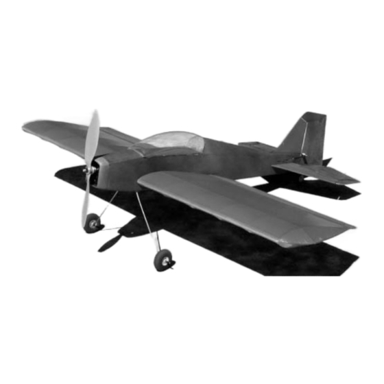
Thank you for purchasing the MiniFlash. The MiniFlash has been designed for the intermediate to
advanced pilot who wants a plane with outstanding performance that will fly in a very limited space
Specifications
Wingspan: 32"
Wing Area: 305 sq. in.
Weight: 10-11 ounces without battery
Wing Loading: 8 oz/sq. ft. depending on battery
September 26, 2002
Last revised January 5, 2003
Copyright 2002, 2003 Douglas Binder, Mountain Models
www.mountainmodels.com
1
Advertisement
Table of Contents

Related Manuals for Mountain Models MiniFlash


Summary of Contents for Mountain Models MiniFlash
- Page 1 MiniFlash Builder’s Manual Thank you for purchasing the MiniFlash. The MiniFlash has been designed for the intermediate to advanced pilot who wants a plane with outstanding performance that will fly in a very limited space Specifications Wingspan: 32” Wing Area: 305 sq. in.
-
Page 2: Required Equipment
Required Building Supplies X-acto with #11 blades Thick and thin CA – Cyanoacrylate glue (Super Glue) Sanding block with 200 grit sandpaper Smooth, flat work table Wax paper to protect plans Needle nose pliers Wire cutters Hobby Iron for applying covering – also called a sealing iron Required Equipment Four channel radio minimum, 5 channel preferred for aileron/ flap mixing Four micro servos: Hitec HS55s recommended... -
Page 3: Fuselage Assembly
Fuselage Assembly ! The fuselage is made up from 1/16” laser cut plywood & 1/16” and 1/32” laser cut balsa. Lay the plans out on a flat worktable and tape them down, and then lay a sheet of wax paper over the plans. - Page 4 ! Lay the 1/16” bottom fuselage sheet on the worktable and glue bulkheads F2/F3, F5, F6, F8, F9, and F10 in place perpendicular to the base. Don’t glue F1 in place yet. Make sure the bulkheads are seated firmly against the bottom sheet. ! Position the two bottom side fuselage stringers and glue with thin CA.
- Page 5 ! Position the 1/16” balsa spar supports in the notches in the fuselage stringers and glue with thin CA. The opening is on the bottom.Position the 1/16” plywood spar supports against the balsa spar supports but don’t glue. Slide the 2”x.7”x1/16” balsa spar separator though the plywood spar supports, which will align them to the balsa spar supports.
- Page 6 guide the pushrods out from the back of the fuselage. Tape the pushrods to the servo tray to temporarily hold them in position. ! The 1/32” balsa turtledeck will be bent over the formers F7-F10. In order to get the balsa to bend that much, wet it down with water.
-
Page 7: Canopy Assembly
! Align the holes in the 2” x ½” x 1/16” plywood landing gear support to landing gear holes in the bottom of the fuselage as shown and glue in to place. The holes will be wider than those in the fuselage. -
Page 8: Wing Assembly
! Position the clear plastic canopy in place over the canopy base. Mark a line with a felt-tip pen around the base of the canopy below the wood canopy floor and the formers. Make the mark 1/8” to 1/4" oversize. Remove the plastic canopy from the canopy base, then trim the canopy to the mark. - Page 9 ! Place the cap spar over the vertical spar and press it into place. ! Install the trailing edge, noting the orientation. The angled end is the outer end and will be on the same side as the pointed end of the vertical spar. ! Slide the wing tip into the vertical spar.
- Page 10 Covering the wings The MiniFlash kit comes with a clear, paintable covering called Doculam which is actually a laminating film. The frosted side has a heat activated adhesive. Unlike most coverings, Doculam does not have a backing sheet. Compared to SoLite (Solarfilm Lite – another excellent choice for the MiniFlash), Doculam is stronger, heavier, and needs a higher temperature to adhere and to shrink.
-
Page 11: Tail Assembly
Finishing the wings ! Glue the end caps onto the 1/8” balsa ailerons. Align the ailerons with the trailing edges of the wings. The notch cut for the control horn is on the side closest to the fuselage. Note that each aileron is tapered to fit with the trailing edge. - Page 12 ! Measure 3/4" from the bottom edge of the rudder and drill a 1/32” hole in the center of the leading edge. Gently push the tail wheel wire into the hole. Glue a piece of Tyvek material around the tail wheel wire where it enters the leading edge of the rudder.
-
Page 13: Aileron Servo
Elevator and Rudder Servo ! Install the rudder and elevator servos into the servo tray. ! Attach the rudder pushrod through the outer hole of a single-horn servo control horn, then install the control horn to the rudder servo. Do the same with the elevator servo. We will now attach the pushrods to the rudder and elevator. -
Page 14: Final Assembly
Timed Motor Stock Motor ! It is a good idea to break your motor in. There are different schools of thought on how to do this but, essentially, you are trying to get the carbon brushes to seat. An easy way to do this is to run the motor for an hour on one cell with no propeller installed. - Page 15 If everything goes well, applying full power will result in a short rollout and a rapid climb. Initiate turns slowly till you get used to the way the MiniFlash flies. Remember that this is a responsive airplane so feed control inputs carefully.
Need help?
Do you have a question about the MiniFlash and is the answer not in the manual?
Questions and answers