
Related Manuals for Mountain Models Tom-E-Boy Micro


Summary of Contents for Mountain Models Tom-E-Boy Micro
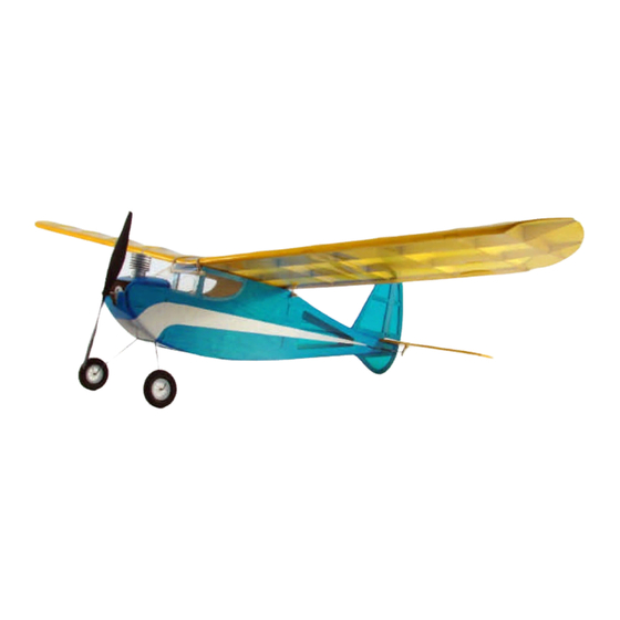
- Page 1 Tom-E-Boy™ Micro Micro Nostalgic R/C Electric Airplane Tom-E-Boy™ Specifications Wingspan: 23.7 in. Length: 18.4 in. Wing Area: 100 sq. in. Weight (Ready to Fly): 1.8 oz. Wing Loading: 2.6 oz. / sq. ft. Version 1.0, March 5, 2012...
-
Page 2: Warranty
WARRANTY Mountain Models guarantees this kit to be free from any defects in both material and workmanship at the time of purchase. This warranty does not cover ANY components or parts damaged by use or modification. In no case shall Mountain Model’s liability exceed the original cost of the purchased kit. Mountain Models reserves the right to modify or change this warranty without notice. -
Page 3: Before You Begin
Before You Begin Check to make sure that all of your parts are there and in good shape. Parts List Number Description of Part in Kit Bundled Parts Laser Cut Parts Sheets (6 Sheets) Plan Sheets (11” x 17”) These instructions of course! Metal (on the back of the wood bundle) 0.020”... -
Page 4: General Building Tips
General Building Tips • READ THE INSTRUCTIONS all the way through and study the plans BEFORE starting any work on the model. • PRE-SANDING: BEFORE removing any parts from the balsa sheets, use a sanding block with 320 grit sandpaper and lightly sand the back of the balsa sheets. Our balsa suppliers have been sending us wood that is over sized, so sanding the backs of the balsa sheets reduces the thickness just slightly and removes any charring from the laser cutting process. - Page 5 1. Slide the 4 ea. W5 ribs, W6 rib, and W7 rib onto the LEFT side of the spars, W1 and W2. Be careful with W6 and W7 since the spars do not rest on your table there. Use a finger on the bottom of the spars when pressing these ribs in place.
- Page 6 8. Slide the 4 ea. W5 ribs, W6 rib, and W7 rib onto the RIGHT side of the spars, W1 and W2. Be careful with W6 and W7 since the spars do not rest on your table there. Use a finger on the bottom of the spars when pressing these ribs in place.
- Page 7 12. Press the W9 leading edge onto W3 and fully up against the ribs. Do NOT glue. 13. After making SURE that all the parts are fully seated against each other and aligned with the plans, and holding the parts down FLAT (small weights are great for this), secure all the joints with thin CA.
- Page 8 17. Press F1 into the plywood F2 part, making SURE that the text on F2 is facing FORWARD and the text on F1 is facing UP. Press F1 into F3. Press F4 into F1. Do NOT glue them yet. 18. Press the plywood F7 into F2. MAKE SURE that the text on F7 is facing UP.
- Page 9 21. Press the other fuselage side onto the crutch assembly. After checking that all parts are fully pressed together, lightly tack the joints with thin CA. 22. Glue the F23 and F24 parts to the INSIDE of the fuselage sides, as shown.
- Page 10 24. Press plywood part LG in place and glue with thin CA. 25. Press the F12 and F13 parts in place, and glue with thin...
- Page 11 26. Press F11 into F10 and then press in place between the fuselage sides. Do NOT glue it yet. 27. Press the two F23 in place, by sliding the back tabs into the former and lowering them down into place, being careful with the thin front section of F23.
- Page 12 29. Press F15 in place. Once again, ensure that the fuselage is straight and glue with thin CA. 30. Using thick CA, glue F20 onto F19, glue F21 onto F20, and glue F22 onto F21, pressed up against F2 and lined up with the fuselage sides.
- Page 13 31. Glue F17 in place, with thin CA. 32. FIT the 3/32" balsa F25 parts onto the F4 former, up against the top F23 parts, as shown. Glue in place with thin or thick CA. 33. Sand the front top of the fuselage to shape as shown on the plans.
- Page 14 37. Assemble the horizontal stabilizer, elevator, vertical fin, rudder, and skid as shown on the plans, with thin CA. 38. Bevel the elevator and rudder, as shown on the plans, and lightly sand the stab, elevator, vertical fin, and rudder with 320 grit sandpaper.
- Page 15 43. Hinge the elevator to the stabilizer using hinge tape, as shown on the plans. There should be a small (1/64") gap between the parts. Do the same for the rudder and vertical fin. 44. Glue the horizontal stab to the fuselage, using the vertical for proper alignment.
- Page 16 48. Glue the plywood control horns into the rudder and elevator, as shown below and on the plans sheet. 49. Follow the directions on page 2 of the plans to make and install the reciever and pushrods.
- Page 17 4 rubber bands, and balance your model where shown on the plans. 53. Enjoy flying your Tom-E-Boy Micro model! If you need help learning how to fly, ask around at a local hobby shop or contact the AMA (Academy of Model...
Need help?
Do you have a question about the Tom-E-Boy Micro and is the answer not in the manual?
Questions and answers