Advertisement
Quick Links
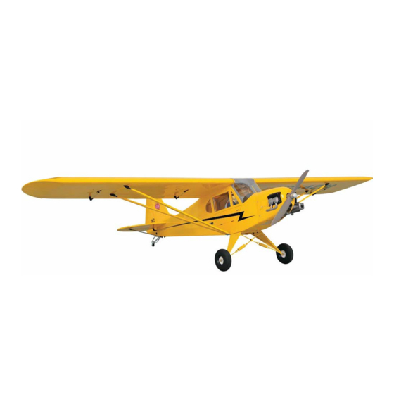
J-3 Cub
Fuselage Kit
J-3 Cub Specifications
Wingspan: 48 in.
Length: 30 in.
Wing Area: 332 sq. in. (Standard Wing)
Weight (Ready to Fly): 13.4 - 17 oz. (Depends on motor & battery)
Wing Loading: 5.8 – 7.6 oz. / sq. ft. (Standard Wing)
Revision History
Date
Revision Notes/Comments
11/28/2006
1.0 Document initial release.
Advertisement

Related Manuals for Mountain Models J-3 Cub


Summary of Contents for Mountain Models J-3 Cub
- Page 1 J-3 Cub Fuselage Kit J-3 Cub Specifications Wingspan: 48 in. Length: 30 in. Wing Area: 332 sq. in. (Standard Wing) Weight (Ready to Fly): 13.4 - 17 oz. (Depends on motor & battery) Wing Loading: 5.8 – 7.6 oz. / sq. ft. (Standard Wing)
-
Page 2: Before You Begin
Thank you for purchasing the Mountain Models 1/9 Scale J-3 Cub. This plane is a scale aileron/elevator/rudder (full house) setup, designed for the low experience pilot on up who wants a super easy flying scale plane. If you have not flown ailerons before, this plane could make a great aileron trainer for you. If you have no tail dragger experience, this plane also makes a great first tail dragger. -
Page 3: Finishing Materials You Will Need
Number Description of Part in Kit Bagged Parts 1/16” x 3/4” x 5.75” Ply Battery Stick 1/4” Balsa Sheet 3/16” Balsa Sheet 1/8” x 4.25” Dowel Micro EZ Servo Connector DuBro Micro EZ Link 4-40 T-Nut 4-40 x 1” Nylon Bolt 2”... -
Page 4: Electronics You Will Need
Electronics You Will Need • 4 channel radio minimum • 4 channel receiver minimum • 2 ea. aileron servos (we recommend either the GWS Picos or Naros) • 2 ea. tail servos (we recommend the Hitec HS55s, or GWS Picos/Naros) •... - Page 5 Step 1: Assembling the Fuselage The first thing you are going to assemble is the fuselage of your airplane. This involves assembling the fuselage sides, formers, stringers, firewall, etc. Glue the 3/32” balsa fuselage side parts together with thin CA. Ensure that they are seated properly with no gaps.
- Page 6 Insert a blind nut on each of the 3/32” balsa C9 triangles as shown below. They go on the “lasered” side of the parts. MAKE SURE the blind nuts are flat against the parts. Secure with a bit of CA around the outside of the blind nut flange. Make SURE you do NOT get CA on the inside threads.
- Page 7 Press the 3/32” balsa F6, with the text facing FORWARD into the RIGHT fuselage side. Insert the 3/32” balsa F4 into the right side with the text facing FORWARD, as shown in the image below left. Make sure they are fully inserted and tack glue them in place, making sure they are at a 90 degree angle to the fuselage side.
- Page 8 11. Insert the 1/8” balsa F16 part into the tops of the formers as shown below. There will be some space between the tops of the middle formers and the top of F16. This is so the formers do not touch the covering when you’re done. Line up the fuselage on the top view of the plans. The top view on the plans might be a bit long, this is OK, just make sure the back end lined up on the center line.
- Page 9 14. Glue the 3/32” cabin top reinforcements in place as shown in the image below. These go inside the cabin and seat against the cabin top (C8) part. 15. Insert the 3/32” balsa reinforcements as shown in the image below. They are on the same sheet as F10.
- Page 10 17. Insert 3 of the blind nuts into the 1/8” Lt Ply firewall as shown below. Make sure you put them on the “lasered” side like below. They are tight, so use a hammer to lightly tap them into place. Make SURE they are flat and add a little thin CA around the outsides of them. It will wick into the holes, gluing them in place.
- Page 11 21. Insert and glue F16 into the bottom rear of the fuselage, with the engraved text inside. 22. Insert the 1/8” fuse bottom stringers as shown below, flush with the fuselage bottom. They are the ones with the square ends. Place them so the “lasered” side is inside the part. Not outside like in the image.
- Page 12 24. Insert the rear ¼” balsa washer support as shown in the image above. Make sure it is fully inserted and secure it with thin CA. You can tell the difference between front and back by making sure the angle is parallel to the fuselage bottom. Insert the front ¼” balsa washer support as shown in the image above.
- Page 13 28. Glue the 2 1/32” front sheeting parts together using thick CA. Line the centerline of the sheeting to the middle of F13 and wrap the sheeting around the formers. Make sure it is aligned and glue it in place with thick CA. Trim any overhang with a sharp blade or sandpaper, so it is flush with the firewall and F2.
- Page 14 31. Insert the RH part with the notch in the center onto the main Rear Hatch part as shown below. Insert the other RH part also shown below. Glue the parts together using thin CA. 32. Glue the magnet onto the rear hatch on the engraved circle with thick CA. Glue in the 2 1/16” plywood hatch tabs (marked R) into place as shown in the left image below.
- Page 15 Step 2: Assembling the Landing Gear Bend the 1/16” landing gear wires, using the plans for your pattern. Be VERY careful and take your time. You want the landing gear to line up nicely, so measure 2-4 times and bend once. There is an extra piece of wire in case you make a mistake.
- Page 16 Glue the other 1/32” ply part to close the wires in the landing gear mount. Use epoxy here to make sure you get a solid glue joint. Clamp the parts together until the glue is dry. After everything is dry, remove the single spider wire holding the center joint together. Trim the 1/16”...
- Page 17 Step 3: Assembling the Tail Parts Assemble the horizontal stab and elevator parts over the plans. After all parts are pressed together, secure each joint with thin CA. Trim the long 1/8” dowel to 4” and glue to the elevators with thick CA or epoxy. Assemble the vertical stab and rudder over the plans.
- Page 18 Assemble the rear fuselage to tail fillets as shown below. MAKE SURE you assemble a LEFT and RIGHT side. Temporarily assemble the tail parts to the fuselage. Place the fillets on the stab against the vertical fin and mark the front of the fillets where they meet F11. Remove the vertical and stab from the fuselage and then place the vertical back in the slots without the stab.
- Page 19 Step 5: Sanding and Covering The next step is to sand the pieces that need to be sanded and cover everything. We aren’t going to go into how to cover the pieces themselves, you’re going to have to refer to your covering’s instructions for this information. Sanding the Cub What we recommend: •...
- Page 20 On the fuselage, sand all surfaces that will be touched by covering for a nice smooth finish when you’re done. Slightly round the corners of the 6 fuselage side stringers and top stringer. Sand the bottom so everything is nicely smooth and flat. Lightly round the bottom corners of the fuselage.
- Page 21 • Clean the inside edges of the 4 aluminum tubes with an X-Acto blade. • Slide the 3/32” OD Aluminum tube over the landing gear axles. Fix them in place with a bit of thin CA wicked into the tubes. DO NOT try to put CA on the wire before the tubes are in place! •...
- Page 22 Step 7: Installing the Tail Feathers For this step, you are going to install the horizontal stabilizer, elevator, the vertical stabilizer and the rudder to the fuselage. When removing covering for gluing parts, be GENTLE with the X-Acto so you don’t cut into the parts! Trim the covering from the slots in the horizontal stabilizer where the vertical fin will go through.
- Page 23 • Installing and hooking up the Control Horns If you covered the control horns, remove the covering on the tab that goes into the rudder and elevator. Trim the covering over the slot that the horns press into on the elevator and rudder.
- Page 24 the top over and glue that part of it. Trim any excess off the top part of the front window after the glue dries. For the vac-formed parts, start with the cowling itself. After trimming it out of the sheet, lay some sandpaper on your flat hard building surface.
- Page 25 Paint the cowling and engine detail with the paint you have chosen. If you use Yellow So-Lite, Krylon Fusion Sunbeam/Safety yellow is a fairly good match. Step 10: Installing the Motor and Cowling We recommend a brushless outrunner rated for around 80 to 100 watts. Installing the Motor Decide which mount you are going to use.
- Page 26 Step 11: Attaching the Receiver and Speed Controller We are not going to cover the receiver and speed controller (ESC) specific information, please refer to your manufacturer’s instructions for more information, if necessary. Attaching the Receiver • The receiver is attached within the fuselage, in front of the servos. Use adhesive Velcro and attach it to fuselage side.
- Page 27 After you attach the battery pack onto the mount, run the 6” double-sided Velcro strip underneath the battery mount, around the top of the battery pack, and then secure it to itself snugly. This acts as a seatbelt, holding the battery pack securely in place. Attaching the Wing Plug the wing into the front mount and use the nylon bolts to secure it on the back.
Need help?
Do you have a question about the J-3 Cub and is the answer not in the manual?
Questions and answers