
Related Manuals for Mountain Models SwitchBack Senior


Summary of Contents for Mountain Models SwitchBack Senior
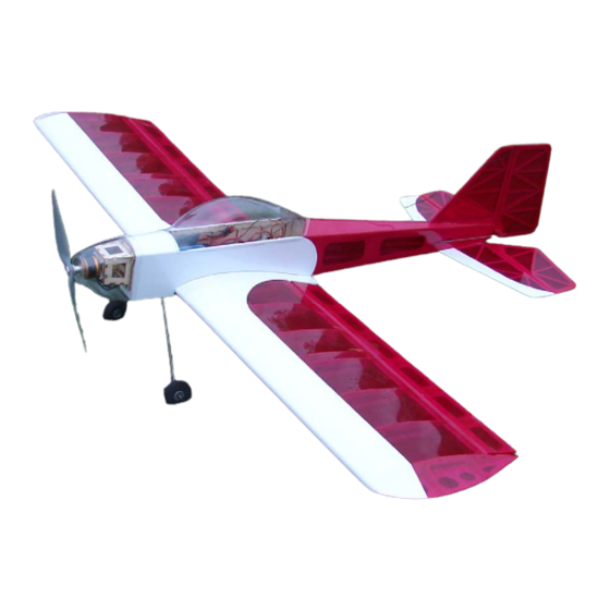
- Page 1 SwitchBack Senior SwitchBack Senior Specifications Wingspan: 55.4 in. Length: 41 in. Wing Area: 597 sq. in. Weight (Ready to Fly): 34 to 37 oz. Wing Loading: 8.2 to 8.9 oz. / sq. ft. Version 1.05, March 3, 2008...
- Page 2 WARRANTY Mountain Models guarantees this kit to be from defects in material and workmanship for the original purchaser. Since we have no control over the assembly of the final model, we accept NO liability for any damage or harm caused by the final product resulting from the user. By building this kit, you accept sole responsibility and liability from its use.
-
Page 3: Before You Begin
Before You Begin Before you begin building your SwitchBack Sr., make sure that all the balsa sheets and hardware are present in your kit. In the unlikely event that something is missing, please contact us immediately and we will send it to you right away. Make sure you read and understand all of the instructions thoroughly before beginning assembly of this kit. -
Page 4: Parts List
Parts List: • This Manual … If you do not have the manual you are holding, please call us. ☺ • Laser Cut Wood 7 ea. 1/16” x 4” x 24” Balsa 4 ea. 1/16” x 3” x 24” Balsa 4 ea. -
Page 5: General Building Tips
General Building Tips • Balsa is a lightweight and fragile wood, so you do need to be careful with it; however, you will also need to use a little bit of force to make everything fit properly, so don’t be too timid. - Page 6 To remove the pieces, gently flex the balsa sheets until the pieces fall out. You may find that you need to carefully trim the extra pieces of wood that originally held the piece to the sheet. Slide the 1/8” Lt. Ply former into position on the 1/8” Plywood crutch as shown below. It is a fairly tight fit, so work it back into position a little at a time.
- Page 7 Assemble the 1/8” balsa rear longerons as shown below. The parts fit best when you assemble the top/bottom parts with one of the lasered sides up and the other down. Lay them on your table as shown below so you make a LEFT and RIGHT side. Press the assembled 1/8” rear fuse parts onto the 1/16”...
- Page 8 Press the 1/8” fuselage sides onto the fuselage crutch as shown below. MAKE SURE that the rear “flush” area of the 1/8” and 1/16” balsa parts is facing to the outside. Do NOT glue this yet. Set the assembly from step 7 on the table with the fuselage crutch assembly. Carefully slide the rear /8”...
- Page 9 11. Weigh the fuselage down to the table to make sure it stays flat and straight and secure all the joints with thin CA. ENSURE that the 1/16” balsa rear fuselage bottom is flush with the 1/8” balsa longerons when you glue these together. Pull the sides together at the front of the fuse, making sure they are fully pressed into the front former nd secure this area with thin CA.
- Page 10 14. Press the rear 1/16” sides into place with the “lasered” side of the part to the inside of the fuselage, as shown below. BEFORE you glue anything, check to see if the pushrod exit slots line up with the holes in the rear 3/32” former. If they don’t, you have the parts on the wrong side.
- Page 11 17. Install the 1/8” Lt Ply part as shown below. MAKE SURE that the holes for the landing gear wires match up with the landing gear supports from step 16. If the holes don’t line up, you will NOT be able to install your landing gear. Now that would really be a pain, wouldn’t it? After it is glued into place, install the 1/8”...
- Page 12 20. Glue the 1/8” Lt Ply cowling mount parts into the front former as shown below. 21. Place some tape behind the second former to protect the fuselage sides. Sand the top front of the fuselage sides to follow the curve of the front 2 formers. Line up the 1/16” top front balsa sheet, so there is the same amount of material hanging off on each side.
- Page 13 22. Glue in place the 1/16” plywood tail wheel wire support as shown below. 23. Install the Red pushrod housing through the holes in the aft 3 formers. They should come forward of the front former by 1/8”. Secure them with thin CA and then trim them flush with the fuselage sides where they exit in the rear.
-
Page 14: Section 2: Assembling The Wings
Section 2: Assembling the Wings Assemble the 1/8” balsa spar as shown in the image below. Make sure the parts are fully pressed together and secure with thin CA. Insert the 1/8” center ribs and the 1/8” front half-ribs as shown in the image below. The 1/8” ribs are on the sheet that had the front fuselage sides on it. - Page 15 Press the 3/32” balsa servo wire guide into place between the rear half ribs. Press the 1/8” balsa support into the rear ½ rib tabs as shown in the upper right image. You’ll need to spread the back of the 1/8” full ribs to get the tabs on the part into the ribs. Install the 1/8”...
- Page 16 Insert the rest of the 3/32” balsa ribs onto the spar, making sure all of the ribs are pressed fully in place. 10. Sand Slide the 3/32” balsa leading edge support into place on the ribs on one side of the wing. MAKE SURE you install it in the right direction.
- Page 17 12. Press the parts from the previous step into place on the back of the ribs, as shown in the image below. MAKE SURE that the angled end goes towards the center section and is on the correct side. Press it into place a little bit at a time until all the ribs are fully seated and it is plugged into the center 1/8”...
- Page 18 15. Slide the 1/16” leading edge parts onto the wing as shown. Work a little at a time along the wing, until it is fully seated against the leading edge support and the ribs. PAY ATTENTION to these parts. The ends of the outboard parts have an angle to them to match the dihedral angle of the wing.
- Page 19 19. Test fit the bottom right wing sheeting and weigh down the wing as shown. Weigh the wing down and secure the sheeting along the back of the spar with thin CA. Pick up the wing and glue the rest of the lower sheeting into place along the front. The sheeting rests on top of the 1/16”...
- Page 20 23. Glue the 3/32” wing tip supports in place as shown in the image below. The shorter of the 2 goes on towards the rear. Secure lightly with thin CA after making sure they are fully pressed into place. Make sure you make a left and right version. Put these in place on the wing tips as shown in the second image, making sure they are pressed fully into place and secure them to the wing with thin CA.
-
Page 21: Section 3: Assembling The Ailerons
26. Sand down the rear center section balsa blocks for the wing bolts to match the rib profile on either side of them. Laying some tape on the ribs will help keep you from sanding into the ribs themselves. 27. Lightly sand the entire wing with 320 and 400 grit sandpaper. The smoother the sanding job, the better the covering will look. - Page 22 Assemble the 3/32” aileron leading edge parts together as shown. ENSURE that they are straight and fully secured, using weights or rulers, and secure with thin CA. Glue the aileron leading edge in place on the aileron as shown. Make sure it is FLAT and STRAIGHT, weighing it down while it is glued.
-
Page 23: Section 4: Assembling The Stabilizer, Elevator, Vertical Fin, And, Rudder
Section 4: Assembling the Stabilizer, Elevator, Vertical Fin, and, Rudder Press the parts together as shown. After the parts are assembled and flat, secure each joint with a drop or 2 of thin CA. - Page 24 Cut the 3/16” dowel to 4-1/8”. Slightly roughen the dowel with some 220 grit sandpaper for a better glue bond. Join the elevator halves with the dowel using 5 minute epoxy. 10. Lightly sand each side of the tail parts with 320 and 400 grit sandpaper. 11.
-
Page 25: Section 5: Assembling The Canopy
You do NOT attach the tail wheel until the rudder is attached to the vertical fin after covering and hinging the rudder to vertical. Drill a hole in the rudder for the wire to press into and cut a slot in the rudder for the hinge that is attached to the tail wheel wire. Slightly indent the balsa rudder where the rest of the wire rests. -
Page 26: Section 6: Covering
Section 6: Covering Covering the SwitchBack Sr. Determine what material you’ll use to cover, we recommend using Solite or SolarFilm covering material since it is extremely lightweight and won’t crush the balsa when shrinking. Please refer to the instructions that came with your covering for details on how to cover if you haven’t done it before. - Page 27 Installing the Elevator • Install the CA hinges into the slots in the stabilizer and slide the elevator onto the CA hinges, so half of the hinge is in each part. Move the elevator through its full range of motion and then secure the hinges by placing a few drops of thin CA on both sides of the hinges at the hinge line.
-
Page 28: Section 8: Attaching The Control Horns
Section 8: Attaching the Control Horns Next, you are going to attach all of the control horns, you will need: • 1 Elevator control horn • 1 Rudder control horn • 2 Aileron control horns Insert the control horns into their appropriate pocket. The Rudder control horn goes on the RIGHT side and the elevator horn goes on the LEFT side. - Page 29 Put an EZ Servo connector in each of the servo control horns. Place Z-Bends in the ends of each of the 2 - 24” and 2 - 12” 1/16” diameter wires. Place the Z-bend ends of the 12” wires into the plywood aileron control horns. Slide the aileron servo horn EZ Connector onto the wire and then onto the servo.
-
Page 30: Section 10: Landing Gear
Section 10: Landing Gear • Slide the landing gear into the holes on the bottom front fuselage. • Place a bend in the end of the wire ties and thread them up though the bottom and then back out on the other side. Pull them tight and trim off the extra, as shown in the image below. -
Page 31: Section 11: Installing The Motor
Section 11: Installing the Motor We recommend a brushless motor rated for around 200 to 300 watts. The prototypes flew outstanding on the Scorpion 3008 and 3S at around 250 watts. Installing the Motor You will want to glue the mounts together with epoxy, rather than CA. Epoxy can handle the vibration of a slightly out of balance propeller better than CA can. -
Page 32: Section 12: Attaching The Receiver And Speed Controller
Section 12: Attaching the Receiver and Speed Controller Attaching the Receiver • The receiver is attached within the fuselage, in front of the servos. Use adhesive Velcro and attach it to the ply crutch. Connect the servos and ESC to the receiver, following the guides on the receiver itself. - Page 33 Setting the Throws You need to adjust your radio trim so that the elevator, rudder, and ailerons are all level. The throws are listed as total travel, and are as follows: Low Rates High Rates Ailerons 1” Full 45 degrees 1”...
Need help?
Do you have a question about the SwitchBack Senior and is the answer not in the manual?
Questions and answers