
Related Manuals for Omron ZX2-LDA41


Summary of Contents for Omron ZX2-LDA41
- Page 1 Smart Sensors Laser Displacement Sensors CMOS Type ZX2 Series User’s Manual Cat. No. Z310-E1-08...
-
Page 2: Table Of Contents
CONTENTS CONTENTS INTRODUCTION PREPARATION Introduction MEASUREMENT Meanings of Signal Words......... . . 8 Meanings of Alert Symbols . - Page 3 Positioning ........... 66 Eccentricity and Surface Deflection .
- Page 4 Introduction Thank you for purchasing the ZX2 Series Smart Sensor. This manual provides CONTENTS information regarding functions, performance and operating methods that are required for using the sensor. INTRODUCTION When using the ZX2 Smart Sensor, make sure to observe the following: •...
- Page 5 Omron’s exclusive warranty is that the Products will be free from defects in materials and PREPARATION workmanship for a period of twelve months from the date of sale by Omron (or such other MEASUREMENT period expressed in writing by Omron). Omron disclaims all other warranties, express or FLOW OF implied.
- Page 6 PRODUCTION OR COMMERCIAL LOSS IN ANY WAY CONNECTED WITH THE PRODUCTS, WHETHER SUCH CLAIM IS BASED IN CONTRACT, WARRANTY, INTRODUCTION NEGLIGENCE OR STRICT LIABILITY. Further, in no event shall liability of Omron Companies exceed the individual price of the PREPARATION Product on which liability is asserted. MEASUREMENT...
- Page 7 INTRODUCTION a guide for the user in determining suitability and does not constitute a warranty. It may represent the result of Omron's test conditions, and the user must correlate it to actual PREPARATION application requirements. Actual performance is subject to the Omron's Warranty and MEASUREMENT Limitations of Liability.
-
Page 8: Meanings Of Signal Words
Meanings of Signal Words CONTENTS The following signal words are used in this manual. INTRODUCTION Indicates a potentially hazardous situation which, if not avoided, will result in minor or moderate injury, or may result in serious injury or death. Additionally there may be significant PREPARATION property damage. -
Page 9: Flow Of Operation
Laser Safety CONTENTS Sensor Head ZX2-LD50L, LD50, LD100L, LD100: Class 2 INTRODUCTION PREPARATION MEASUREMENT Never look into the laser beam. FLOW OF OPERATION Doing so continuously will result in visual impairment. BASIC SETUP Do not disassemble the product. MAIN APPLICATIONS Doing so may cause the laser beam to leak, resulting in the danger of &... - Page 10 In Europe, diffuse-reflective models in the ZX2 Series are categorized as Class 2 laser products and the regular-reflective model is classified as a Class 1 laser product according to EN60825-1 (see note). CONTENTS The CE markings on the products also reflect these categorizations. In the U.S.A., diffuse-reflective models in the ZX2 Series are categorized as Class II laser INTRODUCTION products, and the regular-reflective model is classified as a Class I laser product...
-
Page 11: Precautions For Safe Use
Precautions for Safe Use Please observe the following precautions for safe use of the products. CONTENTS Installation Environment INTRODUCTION • Do not use the product in environments where it can be exposed to inflammable/ explosive gas. PREPARATION • Do not install the product close to high-voltage devices and power devices in order MEASUREMENT to secure the safety of operation and maintenance. -
Page 12: Main Applications & Setting
Precautions for Correct Use Please observe the following precautions to prevent failure to operate, malfunctions, or Please observe the following precautions to prevent failure to operate, malfunctions, or CONTENTS undesirable effects on product performance. undesirable effects on product performance. Installation of the Product Installation of the Product INTRODUCTION Installation Site... - Page 13 Warming Up After turning ON the power supply, allow the product to stand for at least 10 minutes before use. The circuits are still unstable just after the power supply is turned ON, so CONTENTS measured values may fluctuate gradually. A warmup of at least 10 minutes is also required after canceling LD-OFF input if LD- INTRODUCTION OFF input is being used.
-
Page 14: Applications
How to Use This Manual Page Format CONTENTS This section explains the page format by using the Setting for MAIN APPLICATIONS AND SETTING METHODS chapter as an example. INTRODUCTION Index label PREPARATION Shows the chapter and header titles with white characters. MEASUREMENT Header Height... -
Page 15: Applications
Meanings of Symbols CONTENTS Symbol Meaning Indicates points that are important to achieve the full product Important performance, such as operational precautions and applica- INTRODUCTION tion procedures. (For details about xxx, Indicates pages where related information can be found. PREPARATION see page xx.) MEASUREMENT Required... -
Page 16: Applications
MEMO CONTENTS INTRODUCTION PREPARATION MEASUREMENT FLOW OF OPERATION BASIC SETUP MAIN APPLICATIONS & SETTING METHODS Height Steps Warpage Double Sheet Detection Thickness Positioning Eccentricity and Surface Deflection DETAILED SETTINGS TROUBLE- SHOOTING SPECIFI- CATIONS INDEX SETTING TRANSITION CHARTS ZX2 User’s Manual... -
Page 17: Preparation For Measurement
PREPARATION FOR MEASUREMENT Part Names and Functions Installation Wiring Diagram... -
Page 18: Part Names And Functions
Part Names and Functions Basic Configuration CONTENTS The basic configuration of the ZX2 series Smart Sensors is shown below. INTRODUCTION PREPARATION Calculating Unit (used for connecting two or more Amplifier Units) MEASUREMENT Power Supply FLOW OF (sold separately) OPERATION Amplifier Unit Extension Cable BASIC (used for extending cable length) *... -
Page 19: Amplifier Unit
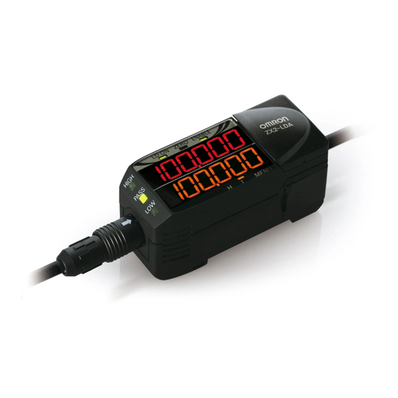
Amplifier Unit CONTENTS Operating Section INTRODUCTION Display section PREPARATION Output Cable Sensor Head connector MEASUREMENT This cable is for connecting the power supply This connector is for connecting and sync sensors or external devices. the Sensor Head. FLOW OF Connector (two connectors, one on each side) OPERATION This connector is for connecting Calculating Units. - Page 20 Digital Displays The information displayed on the main and sub-displays depends on the currently CONTENTS selected mode. The default mode is the RUN mode. When the power is turned ON, the model of Amplifier Unit (ZX2-LDA) will be displayed on the main display and the channel number will be displayed on the sub-display.
-
Page 21: Button Operation
Button Operation The functions of buttons change according to the currently selected mode. CONTENTS Button type Button function INTRODUCTION RUN mode MENU mode • Normal press: Function changes depending on the button Changes the sub-display content.* setting. PREPARATION • Switches the function display. button •... -
Page 22: And Sensor Head
Sensor Head CONTENTS Emission center position mark This mark indicates the emission center position. FAR Indicator (green) Emitting See the table below. INTRODUCTION section Laser life indicator (red) PREPARATION N E A MEASUREMENT NEAR Indicator (green) Receiving See the table below. section CMOS position mark FLOW OF... -
Page 23: Double Installation
Installation Important CONTENTS Before connecting/disconnecting Smart Sensor components, make sure that the power to the Amplifier Unit is turned OFF. The Smart Sensor may malfunction if components are connected or removed while the power is ON. INTRODUCTION Installing Sensor Heads PREPARATION MEASUREMENT Installation Method... - Page 24 • Be sure to attach the ferrite core accessory to the Sensor Head. Attach it within 100 mm of the Sensor Head side. Within 100 mm CONTENTS 16.5 dia. INTRODUCTION Made by TDK Corporation ZCAT1730-0730A PREPARATION Important MEASUREMENT • When mounting a Sensor Head, take care not to touch the emitter and receiver. Finger marks on the emitter and receiver may hinder correct measurements.
-
Page 25: Installing The Amplifier Unit
Installing the Amplifier Unit Amplifier Units can be easily mounted to 35-mm DIN Track. CONTENTS Installation Method INTRODUCTION Hook the connector end of the Sensor Head on the DIN Track, and press in at the bottom PREPARATION until the Amplifier Unit locks into place. If necessary, fix it in place by the End Plate. MEASUREMENT DIN Track (Option) FLOW OF... -
Page 26: Thickness Connecting Calculating Units
Connecting Calculating Units CONTENTS Use a Calculating Unit to connect Amplifier Units when performing calculations between Amplifier Units and to prevent mutual interference between Sensor Heads. The number of Amplifier Units that can be connected differs depending on the functions to INTRODUCTION be used. -
Page 27: Connection Method
Connection Method CONTENTS INTRODUCTION PREPARATION MEASUREMENT FLOW OF OPERATION BASIC SETUP Open the connector cover on the Amplifier Unit. MAIN APPLICATIONS & SETTING Open the connector cover by lifting and sliding it. METHODS Height Mount the Calculating Unit to the DIN Track. Steps Slide and connect the Calculating Unit to the Amplifier Unit connector. -
Page 28: Connecting The Sensor Head To The Amplifier Unit
Connecting the Sensor Head to the Amplifier Unit CONTENTS Installation Method INTRODUCTION Align the position of the connector mark with the mark on the Amplifier Unit, and insert the connector until it is locked in place. PREPARATION MEASUREMENT FLOW OF OPERATION BASIC SETUP... - Page 29 CONTENTS Removal Method INTRODUCTION To disconnect the Sensor Head, hold the Sensor Head's connector ring and the Amplifier Unit connector, and then pull them straight out. PREPARATION MEASUREMENT Connector Ring FLOW OF OPERATION BASIC SETUP Important MAIN APPLICATIONS • Do not touch the terminals inside the connector. &...
-
Page 30: Wiring Diagram
Wiring Diagram Wiring Input/Output Cables CONTENTS The input/output cable has the following wires. INTRODUCTION Important PREPARATION Wire the cable correctly. Incorrect wiring may damage the Smart Sensor. (For details on the cable’s conductor cross-section and insulation resistance, see page 136.) MEASUREMENT Brown Power supply... - Page 31 Cable Name Function color Black Analog output The analog output outputs a current or voltage in CONTENTS accordance with the measured value. (For details on setting method, see page 109.) Shield Analog GND (0 V) The analog GND terminal is the 0 V terminal for the analog INTRODUCTION output.
- Page 32 Cable Name Function color Reset input/BANK Reset input: input 1 (switched While a reset signal is being input, is displayed CONTENTS by external input on the sub-display. setting) • When the hold function is not used The output while a reset signal is being input is held in INTRODUCTION accordance with the output during non-measurement setting.
-
Page 33: I/O Circuit Diagrams
I/O Circuit Diagrams CONTENTS NPN Amplifier Unit (Negative Common) INTRODUCTION PREPARATION Brown 10 to 30 VDC MEASUREMENT Load FLOW OF White HIGH judgement output Load OPERATION Load Load Green PASS judgement output 10 to BASIC 30 VDC Gray LOW judgement output SETUP Yellow Error output MAIN... - Page 34 CONTENTS PNP Amplifier Unit (Positive Common) INTRODUCTION PREPARATION Brown 10 to 30 VDC MEASUREMENT 10 to 30 VDC White HIGH judgement output FLOW OF OPERATION Green PASS judgement output BASIC Gray LOW judgement output Load SETUP Load Yellow Error output Load MAIN Load...
-
Page 35: Flow Of Operation
FLOW OF OPERATION FLOW OF OPERATION... -
Page 36: Detailed Flow Of Operation
FLOW OF OPERATION CONTENTS Preparation for Measurement INTRODUCTION Installing the Sensor p. 23 PREPARATION MEASUREMENT Wiring Diagram p. 30 FLOW OF OPERATION BASIC SETUP Setup MAIN APPLICATIONS <Simple Measurement> <Setting Up by 6 Measurement Contents> & SETTING METHODS • Basic Setup p. 40 •... - Page 37 CONTENTS Detailed Settings INTRODUCTION (Optimizing the Sensing Conditions) • Smart Tuning p. 80 PREPARATION • Selecting the Initial Sub-Display p. 84 • Connecting Two or More Amplifier Units p. 86 MEASUREMENT • Mutual Interference Prevention p. 88 • Setting the Hysteresis p.
- Page 38 MEMO CONTENTS INTRODUCTION PREPARATION MEASUREMENT FLOW OF OPERATION BASIC SETUP MAIN APPLICATIONS & SETTING METHODS Height Steps Warpage Double Sheet Detection Thickness Positioning Eccentricity and Surface Deflection DETAILED SETTINGS TROUBLE- SHOOTING SPECIFI- CATIONS INDEX SETTING TRANSITION CHARTS FLOW OF OPERATION ZX2 User’s Manual...
-
Page 39: Basic Setup
BASIC SETUP BASIC SETUP... -
Page 40: Shooting Basic Setup
Default Settings p.123 BASIC SETUP Initializing Settings p.123 Setting Transition Charts p.158 Display of RUN Mode CONTENTS LOW threshold Analog output value HIGH threshold 5 V, 1 to 5 V INTRODUCTION 40 to 20 mA PREPARATION MEASUREMENT FLOW OF OPERATION Current value Resolution BASIC... - Page 41 MAIN APPLICATIONS & SETTING METHODS Height Steps and Warpage Double Sheet Detection Thickness Positioning Eccentricity and Surface Deflection...
-
Page 42: Index Height
Height CONTENTS INTRODUCTION PREPARATION MEASUREMENT Procedure for setting up height FLOW OF OPERATION Sensor installation/wiring Hold Other than BASIC Set to the MENU mode Trigger conditions SETUP Response time setting Threshold setting MAIN APPLICATIONS Required setting & SETTING METHODS Return to RUN mode Smart tuning Optional setting Height... - Page 43 Button Explanation of Display Description of Operation Operation Selection Menu Press the button to apply the setting. CONTENTS Select the response time to match the size Required Response time setting and moving speed of the sensing object. INTRODUCTION Button Explanation of Display Description of Operation Operation...
- Page 44 Set this item to hold measured values during the measurement Optional Hold period according to preset hold conditions. Button Explanation of Display Description of Operation Operation Selection Menu CONTENTS Press the button to display Default value: OFF INTRODUCTION PREPARATION Press the button to select the MEASUREMENT hold conditions.
- Page 45 Button Explanation of Display Description of Operation Operation Selection Menu Press the button to select the trigger conditions. Enter the trigger by using the CONTENTS timing input or by pressing button in the RUN Select the Press to select mode. The period that the desired value.
- Page 46 Set the range of measured values to be judged as Required PASS by setting the HIGH and LOW thresholds. Threshold setting Button Explanation of Display Description of Operation CONTENTS Operation Selection Menu Press the button to display Setting example: the HIGH threshold. Non-defective product INTRODUCTION height 0 to 10 mm...
-
Page 47: Steps And Warpage
Steps and Warpage CONTENTS INTRODUCTION PREPARATION MEASUREMENT Procedure for setting up steps and warpage FLOW OF The Amplifier Units to set up differ depending on whether mutual interference prevention OPERATION is set to ON or OFF. Note that different channels are used to specify each menu item, as shown below. BASIC SETUP CH1 (ON) - Page 48 Button Explanation of Display Description of Operation Operation Selection Menu Press the button to display CONTENTS INTRODUCTION Press the button to set the display to to set display of the detail menu. PREPARATION Press to display. MEASUREMENT Press the button to apply FLOW OF the setting.
- Page 49 Button Explanation of Display Description of Operation Operation Selection Menu Press the button to select the Select the response time to match the size and moving response time. CONTENTS speed of the sensing object. Select the Press to select 60 µs, 120 µs, 240 µs, 500 µs, desired value.
- Page 50 Set this item when calculating the difference between the measurement results from two Required 2-sensor operation (A-B) Sensor Heads. The measurement result for CH1 is substracted from the measurement result of the channel being set. CONTENTS (Use CH2 for these settings.) Button Explanation of Display...
- Page 51 Button Explanation of Display Description of Operation Operation Selection Menu Press the button to enable * If the button is pressed setting of the HIGH threshold. when the cursor is at the CONTENTS right-most digit or the button is pressed when the Press the button to move cursor is at the left-most digit,...
-
Page 52: Double Sheet Detection
Double Sheet Detection CONTENTS INTRODUCTION PREPARATION MEASUREMENT Procedure for setting up double sheet detection FLOW OF OPERATION Sensor installation/wiring Hold Other than BASIC Set to the MENU mode Trigger conditions SETUP MAIN Response time setting Threshold setting APPLICATIONS & SETTING Required setting METHODS Smart tuning... - Page 53 Button Explanation of Display Description of Operation Operation Selection Menu Press the button to apply the setting. CONTENTS Select the response time to match the size INTRODUCTION Required Response time setting and moving speed of the sensing object. Button Explanation of PREPARATION Display Description of Operation...
- Page 54 Set this item to hold measured values during the measurement Optional Hold period according to preset hold conditions. Button Explanation of Display Description of Operation Operation Selection Menu CONTENTS Press the button to display Default value: OFF INTRODUCTION PREPARATION Press the button to select the hold conditions.
- Page 55 Button Explanation of Display Description of Operation Operation Selection Menu Press the button to select the trigger conditions. Enter the trigger by using the CONTENTS timing input or by pressing button in the RUN Select the Press to select mode. The period that the desired value.
- Page 56 Set the range of measured values to be judged as PASS by setting the HIGH and LOW thresholds. Required Threshold Setting Button Explanation of Display Description of Operation Operation Selection Menu CONTENTS Press the button to display Examples: the HIGH threshold. INTRODUCTION -0.5 PREPARATION...
-
Page 57: Thickness
Thickness CONTENTS INTRODUCTION PREPARATION MEASUREMENT Procedure for setting up thickness FLOW OF The Amplifier Units to set up differ for each menu. Note also that different channels are OPERATION used to specify each menu item, as shown below. BASIC SETUP Sensor installation/wiring 2-sensor operation (thickness) Required setting... - Page 58 Button Explanation of Display Description of Operation Operation Selection Menu Press the button to display CONTENTS INTRODUCTION Press the button to set the display to to set display of the detail menu. PREPARATION Press to display. MEASUREMENT Press the button to apply FLOW OF the setting.
- Page 59 Button Explanation of Display Description of Operation Operation Selection Menu Press the button to select the Select the response time to match the size and moving response time. CONTENTS speed of the sensing object. Select the Press to select 60 µs, 120 µs, 240 µs, 500 µs, desired value.
- Page 60 Make this initial setting to measure thickness when using two Sensor Head to measure Required 2-sensor operation (thickness) thickness. (Use CH2 for these settings.) CONTENTS Button Explanation of Display Description of Operation Operation Selection Menu Set the reference sensing object INTRODUCTION of which thickness is known in Calculating Unit...
- Page 61 Important • If analog output is to be used, the entered thickness value is used as the center value of the analog output range. (For example, 0 V is used if the analog output is ±5 V.) • After thickness calculation, the maximum and minimum measurement range values (CH2 CONTENTS measurement values) are assigned as the maximum and minimum analog output range.
- Page 62 Set this item to hold measured values during the measurement Optional Hold period according to preset hold conditions. (Use CH2 for these settings.) Button Explanation of CONTENTS Display Description of Operation Operation Selection Menu Press the button on the CH2 Default value: OFF INTRODUCTION Amplifier Unit to display...
- Page 63 Set how timing of the hold measurement Optional period is to be input. Trigger conditions (Use CH2 for these settings.) Button Explanation of CONTENTS Display Description of Operation Operation Selection Menu Press the button on the CH2 Default value: TIMING INTRODUCTION Amplifier Unit to display PREPARATION...
- Page 64 Button Explanation of Display Description of Operation Operation Selection Menu Press the button to move * If the button is pressed [Change numeric value] the digit, press the button to when the cursor is at the CONTENTS change the numeric value, and right-most digit or the set the self-trigger level.
- Page 65 Switch to the mode in which measurement Required Return to RUN mode is performed. (Use CH1 and CH2 for these settings.) Button Explanation of Display Description of Operation CONTENTS Operation Selection Menu Hold down the button for INTRODUCTION three seconds to switch to the Hold down for RUN mode.
-
Page 66: Positioning
Positioning CONTENTS INTRODUCTION PREPARATION MEASUREMENT Procedure for setting up positioning FLOW OF OPERATION Sensor installation/wiring Scaling BASIC SETUP Set to the MENU mode Threshold setting MAIN Response time setting Return to RUN mode APPLICATIONS & SETTING Required setting METHODS Smart tuning Setting completed Optional setting Height... - Page 67 Button Explanation of Display Description of Operation Operation Selection Menu Press the button to set the display to to set display of CONTENTS the detail menu. Press to display. INTRODUCTION Press the button to apply the setting. PREPARATION MEASUREMENT Select the response time to match the size Required Response time setting and moving speed of the sensing object.
- Page 68 Smart tuning sets optimum sensing conditions according to the operating conditions Required Smart tuning (response time and color/state of workpiece) Button Explanation of Display Description of Operation Operation Selection Menu CONTENTS Check that the reference — — workpiece is set in place. INTRODUCTION If "...
- Page 69 Button Explanation of Display Description of Operation Operation Selection Menu Press the button to display <To display the actual sensing distance> CONTENTS INTRODUCTION Press the button to enable -8 0 8 setting of S1-Before. 58 50 42 PREPARATION MEASUREMENT Press the button to move [Change numeric value] the digit, press the...
- Page 70 Button Explanation of Display Description of Operation Operation Selection Menu Press the button to display CONTENTS After INTRODUCTION Press the button to enable Before setting of S2-Before. PREPARATION * If the button is pressed MEASUREMENT Press the button to move [Change numeric value] when the cursor is at the the digit, press the...
- Page 71 Set the range of measured values to be judged as PASS by setting the HIGH and LOW thresholds. Required Threshold Setting Button Explanation of Display Description of Operation Operation Selection Menu CONTENTS Press the button to display Setting example: the HIGH threshold. Non-defective product INTRODUCTION position 49 to 51 mm...
-
Page 72: Eccentricity And Surface Deflection
Eccentricity and Surface Deflection CONTENTS INTRODUCTION PREPARATION MEASUREMENT Procedure for setting up eccentricity and surface deflection FLOW OF OPERATION Sensor installation/wiring Hold Other than Set to the MENU mode BASIC Trigger conditions SETUP Response time setting MAIN Threshold setting APPLICATIONS Smart tuning &... - Page 73 Button Explanation of Display Description of Operation Operation Selection Menu Press the button to apply the setting. CONTENTS Select the response time to match the size Required Response time setting INTRODUCTION and moving speed of the sensing object. Button Explanation of Display Description of Operation PREPARATION...
- Page 74 Set this item to change the display scale when you want to display a digital value on the Amplifier Unit different from the Optional Scaling actual measured value. (e.g. to reverse the - and + indications) Button Explanation of Display Description of Operation CONTENTS Operation...
- Page 75 Button Explanation of Display Description of Operation Operation Selection Menu Press the button to display CONTENTS Before Press the button to enable INTRODUCTION setting of S2-Before. After PREPARATION Press the button to move MEASUREMENT [Change numeric value] the digit, press the button to * If the button is pressed...
- Page 76 Button Explanation of Display Description of Operation Operation Selection Menu Press the button to select the hold conditions. Hold OFF CONTENTS The average measured value Select the Press to select during the sampling period is desired value. INTRODUCTION held. PREPARATION The difference between the minimum and maximum MEASUREMENT...
- Page 77 Button Explanation of Display Description of Operation Operation Selection Menu Press the button to select the trigger conditions. Enter the trigger by using the CONTENTS timing input or by pressing button in the RUN Select the Press to select mode. The period that the desired value.
- Page 78 Set the range of measured values to be judged as PASS by setting the HIGH and LOW thresholds. Required Threshold Setting Button Explanation of Display Description of Operation Operation Selection Menu CONTENTS Press the button to display Setting example: the HIGH threshold. Non-defective product INTRODUCTION eccentricity -1 to 1 mm...
- Page 79 DETAILED SETTINGS Smart Tuning (Optimizing the Sensing Conditions) Selecting the Initial Sub-Display Connecting Two or More Amplifier Units Mutual Interference Prevention Setting the Hysteresis (Improving Unstable Measurement Near the Judgement Threshold) Setting the Hold Function (Holding Measured Values Under Special Conditions) Bank Setting Zero Reset Scaling...
-
Page 80: Detailed Settings
Setting channels used when connecting multiple units Smart Tuning If mutual interference prevention is ON: CH1 If mutual interference prevention is set to OFF: Each CH Smart tuning: CONTENTS This setting option sets optimum sensing conditions according to the operating conditions (response time and color/state of workpiece). - Page 81 Button Explanation of Display Description of Operation Operation Selection Menu Press the button to select the Select the response time to match the size and moving response time. CONTENTS speed of the sensing object. Select the Press to select 60 µs, 120 µs, 240 µs, 500 µs, desired value.
- Page 82 (2) Tuning of multiple stationary workpieces: Multi-smart tuning (a mix of workpieces having different color and state) Button Explanation of Display Description of Operation Operation Selection Menu CONTENTS Set reference workpiece 1 in — — place. INTRODUCTION Press the button for three Pressing down seconds.
- Page 83 (3) Tuning of workpieces having different surface states: Active smart tuning (execution of tuning while workpieces are moving) Button Explanation of Display Description of Operation Operation Selection Menu CONTENTS Press the button for five Pressing down seconds with the workpiece set Hold down for in place.
-
Page 84: Selecting The Initial Sub-Display
Selecting the Initial Sub-Display Setting channels used when connecting multiple units: Each CH Initial sub-display: CONTENTS The initial sub-display is the display that appears when the power is turned on. INTRODUCTION Procedure for setting up initial sub-display Set to the MENU mode PREPARATION MEASUREMENT Sub-display memory setting... - Page 85 Button Explanation of Display Description of Operation Operation Selection Menu Press the button to apply the setting. CONTENTS Return to RUN mode INTRODUCTION Button Explanation of Display Description of Operation Operation Selection Menu PREPARATION Hold down the button for MEASUREMENT three seconds to switch to the Hold down for FLOW OF...
-
Page 86: Connecting Two Or More Amplifier Units
Connecting Two or More Amplifier Units Use a Calculating Unit to connect Amplifier Units when performing calculations between CONTENTS Amplifier Units and to prevent mutual interference between Sensor Heads. The number of Amplifier Units that can be connected differs depending on the functions to be used. -
Page 87: Introduction
The displayed and set up menus differ depending on the channel when two or more Amplifier Units are connected and when mutual interference prevention is set to ON. Use the Amplifier Units of the corresponding channel numbers to specify settings by CONTENTS referring to the tables below. -
Page 88: Mutual Interference Prevention
Mutual Interference Prevention Setting channel: CH1 Mutual interference prevention: CONTENTS This refers to the function for preventing the influence of Sensor Heads when mounted close to each other. (This function can be used for up to five Amplifier Units connected by using Calculating Units (ZX2-CAL).) INTRODUCTION Procedure for setting up mutual interference prevention PREPARATION... - Page 89 Mutual interference prevention setting Button Explanation of Display Description of Operation Operation Selection Menu CONTENTS Press the button to display Default value: OFF INTRODUCTION Press the button to display PREPARATION MEASUREMENT FLOW OF Press to display. OPERATION Press the button to apply the setting.
- Page 90 <Response time if mutual interference prevention is set to ON> CH1 Response Time Setting Response Time per Unit 60 µs 3 ms 120 µs 3 ms 240 µs 3 ms CONTENTS 500 µs 4 ms 1 ms 8 ms 2 ms 16 ms INTRODUCTION 4 ms...
-
Page 91: Setting The Hysteresis
Setting the Hysteresis Setting channels used when connecting multiple units: Each CH Hysteresis width: CONTENTS This refers to the difference between the operation point and return point. Set the hysteresis width for the upper and lower limits of the judgements if the HIGH, PASS or LOW judgement is unstable near the threshold values. - Page 92 Hysteresis width setting Button Explanation of Display Description of Operation Operation Selection Menu CONTENTS Press the button to display Default value: 0.000 INTRODUCTION Press the button to enable PREPARATION setting of the hysteresis width. MEASUREMENT FLOW OF Press to display. OPERATION Press the button to move...
-
Page 93: Setting The Hold Function
Setting the Hold Function Setting channels used when connecting multiple units: Each CH Hold: CONTENTS The hold function holds any values during the measurement period (sampling period), and outputs these values at the end of measurement. INTRODUCTION Procedure for setting up hold Set to the MENU mode PREPARATION MEASUREMENT... -
Page 94: Preparation
Hold conditions setting Button Explanation of Display Description of Operation Operation Selection Menu CONTENTS Press the button to display Default value: OFF INTRODUCTION Press the button to select the PREPARATION hold conditions. Hold OFF MEASUREMENT The average measured value Select the FLOW OF Press to select during the sampling period is... -
Page 95: Preparation
Selection menu Details OFF (default) Hold measurement is not performed. The measured value is output at all times. CONTENTS The average measured value during the sampling period is held. The output changes at the end of the sampling period and is held until the end of the next sampling period. -
Page 96: Preparation
Self-trigger setting Button Explanation of Display Description of Operation Operation Selection Menu CONTENTS Press the button to display Default value: TIMING INTRODUCTION Press the button to select the PREPARATION self-trigger. Enter the trigger by using the MEASUREMENT timing input or by pressing button in the RUN Select the FLOW OF... -
Page 97: Preparation
Selection menu Details Either input the timing signal from an external device, or enter the trigger for starting sampling by pressing the button. The period that the timing CONTENTS signal is ON is the sampling period. (Default) Timing input INTRODUCTION Sampling period (For details on external inputs, see page 118.) PREPARATION... -
Page 98: Preparation
Button Explanation of Display Description of Operation Operation Selection Menu Press the button to apply the setting. CONTENTS Return to RUN mode INTRODUCTION Button Explanation of Display Description of Operation Operation Selection Menu PREPARATION Hold down the button for MEASUREMENT three seconds to switch to the FLOW OF Hold down for... -
Page 99: Bank Setting
Setting channels used when connecting multiple units Bank Setting Bank switching: CH1 Bank registration: Each CH Bank setting: CONTENTS Up to four sets of settings can be stored in memory. (Default: bank 0) This is recommended, for example, when measuring on multi-lot lines. INTRODUCTION Procedure for setting up banks PREPARATION... - Page 100 Bank switching Button Explanation of Display Description of Operation Operation Selection Menu CONTENTS Press the button to display Default value: 0 INTRODUCTION Press the button to select the PREPARATION bank. MEASUREMENT Select the FLOW OF Press to select OPERATION desired value. Press the button to apply BASIC...
-
Page 101: Zero Reset
Zero Reset Setting channels used when connecting multiple units: Each CH Zero reset: CONTENTS This refers to setting the reference value to "0" or any desired numeric value so that the measured value can be displayed and output as a positive or negative deviation (tolerance) from the reference value. - Page 102 Procedure for setting up zero reset Set to the MENU mode Zero reset memory setting CONTENTS Display setting at zero reset Return to RUN mode INTRODUCTION Zero reset execution PREPARATION Setting completed MEASUREMENT Set to the MENU mode FLOW OF Button Explanation of OPERATION...
- Page 103 Button Explanation of Display Description of Operation Operation Selection Menu Press the button to apply the setting. CONTENTS Important INTRODUCTION • If zero reset memory is set to ON, the zero reset level will be written in the Amplifier Unit's non-volatile memory (EEPROM) each time a zero reset is executed.
- Page 104 Zero reset execution Button Explanation of Display Description of Operation Operation Selection Menu CONTENTS Set the sensing object to be — — used for executing the zero reset. INTRODUCTION Either press the button for (For details on external LD ON ZERO ENABLE one second in the RUN mode, inputs, see page 118.)
-
Page 105: Flow Of Operation
Scaling Setting channels used when connecting multiple units: Each CH Scaling: CONTENTS The display scale can be changed when you want to display a digital value on the Amplifier Unit different from the actual measured value. (For example, when you want to set the measured value as the actual measuring distance.) INTRODUCTION PREPARATION... - Page 106 Button Explanation of Display Description of Operation Operation Selection Menu Press the button to display CONTENTS Press to display. Press the button to enable INTRODUCTION setting of scaling. Press the button to display <To display the actual sensing PREPARATION distance> MEASUREMENT FLOW OF OPERATION...
- Page 107 Button Explanation of Display Description of Operation Operation Selection Menu Press the button to display CONTENTS After Press the button to enable Before INTRODUCTION setting of S2-Before. PREPARATION * If the button is pressed Press the button to move [Change numeric value] MEASUREMENT when the cursor is at the the digit, press the...
- Page 108 Important • Analog output when specifying the scaling setting The analog output range is assigned based on the post-scaling display value setting range (between S1-AFT and S2-AFT). CONTENTS Concerning the minimum and maximum analog output values, the analog output minimum value is output for the smaller of the post-scaling display values (S1-AFT/S2-AFT), and the analog output maximum value is output for the larger of these values.
-
Page 109: Analog Output
Analog Output Setting channels used when connecting multiple units: Each CH Analog output: CONTENTS This refers to the conversion of measurement results to 4 to 20 mA current output or to -5 to +5 V/1 to 5 V voltage output. The relationship between display values and analog output values can be freely INTRODUCTION specified. - Page 110 Return to RUN mode Button Explanation of Display Description of Operation Operation Selection Menu CONTENTS Hold down the button for three seconds to switch to the Hold down for RUN mode. 3 seconds INTRODUCTION Freely specifying the relationship between display values and analog output values PREPARATION (equivalent to the former ZX-L-N monitor focus) MEASUREMENT...
-
Page 111: Output For Non-Measurement
Output for Non-measurement Setting channels used when connecting multiple units: Each CH Output for non-measurement: CONTENTS This refers to specifying the output contents when an error occurs (Error-dark or Error-bright), when a reset is being input, or before measured values are finalized. (For details on these errors, see page 130.) INTRODUCTION Output Contents... - Page 112 Output settings for non-measurement Button Explanation of Display Description of Operation Operation Selection Menu CONTENTS Press the button to display Default value: KEEP INTRODUCTION Press the button to select PREPARATION output for non-measurement. The measured value status MEASUREMENT before measurement is stopped is held and output.
- Page 113 Return to RUN mode Button Explanation of Display Description of Operation Operation Selection Menu CONTENTS Hold down the button for three seconds to switch to the Hold down for RUN mode. 3 seconds INTRODUCTION PREPARATION MEASUREMENT FLOW OF OPERATION BASIC SETUP MAIN APPLICATIONS...
-
Page 114: Timer
Timer Setting channels used when connecting multiple units: Each CH Timer: The timing for judgement outputs can be adjusted to match the operation of external CONTENTS devices. (Timer accuracy: Up to 1 ms) INTRODUCTION Procedure for setting up the timer PREPARATION Set to the MENU mode MEASUREMENT... - Page 115 Button Explanation of Display Description of Operation Operation Selection Menu Press the button to move [Change numeric value] the digit, press the button to * If the button is pressed CONTENTS change the numeric value, and when the cursor is at the set the time set to the timer.
-
Page 116: Setting The Differential Function
Setting the Differential Function Setting channels used when connecting multiple units: Each CH Differential function: This function is used to display measurement change amounts when it is difficult to CONTENTS specify a threshold for the measured value, making it easier to detect only sudden changes in the measured values. -
Page 117: Applications
Button Explanation of Display Description of Operation Operation Selection Menu Press the button to display * This step is not required if detail menu display is CONTENTS already set to ON in the MENU mode. Press the button to set the INTRODUCTION display to to set display of... -
Page 118: External Input For Bank, Timing Input, Reset Input
External Input for Bank, Timing Input, Reset Input Setting channels used when connecting multiple units: Each CH, Bank switching: CH1 External input: CONTENTS This refers to inputting the bank switching signal, the timing signal during a hold and the reset signal from an external device to execute these operations. INTRODUCTION Procedure for setting up external input PREPARATION... - Page 119 Button Explanation of Display Description of Operation Operation Selection Menu Press the button to select the external input terminal. timing input/reset input CONTENTS Bank switching Select the Press to select desired value. INTRODUCTION Press the button to apply the setting. PREPARATION MEASUREMENT Return to RUN mode...
-
Page 120: Setting The Detection Surface Selection
Setting the Detection Surface Selection Setting channels used when connecting multiple units: Each CH Detection surface selection: The default value is FIRST. Setting the value to MAX can decrease incorrect CONTENTS measurements caused by diffused reflection or multireflection due to the shape of the workpiece. -
Page 121: Applications
Detection surface selection setting Button Explanation of Display Description of Operation Operation Selection Menu CONTENTS Press the button to display INTRODUCTION Press the button to display PREPARATION During normal measurement MEASUREMENT Select the When an incorrect Press to select FLOW OF desired value. -
Page 122: Setting Methods
Key Lock Function Setting channels used when connecting multiple units: Each CH Key Lock Function: CONTENTS The key lock function disables all keys. Once keys have been disabled, no key input will be accepted until the lock is released. This function is useful for preventing inadvertent changes to settings. -
Page 123: Initializing Settings Data
Initializing Settings Data Setting channels used when connecting multiple units: Each CH Initialization: This function resets all settings to their default values. CONTENTS Default Values Function Default Value INTRODUCTION Measurement center distance Display 0 reference: NEAR side + indication: PREPARATION FAR side - indication: MEASUREMENT... -
Page 124: Warpage
Procedure for initializing settings data Set to the MENU mode Setting data initialization CONTENTS Return to RUN mode INTRODUCTION Setting completed Important PREPARATION • When connecting two or more Amplifier Units, use CH1 to perform initialization because CH2 MEASUREMENT and later channels cannot be used to do this. FLOW OF Note that CH2 and later channels are initialized together with CH1. -
Page 125: Warpage
Return to RUN mode Button Explanation of Display Description of Operation Operation Selection Menu CONTENTS Hold down the button for three seconds to switch to the Hold down for RUN mode. 3 seconds INTRODUCTION PREPARATION MEASUREMENT FLOW OF OPERATION BASIC SETUP MAIN APPLICATIONS... -
Page 126: Warpage
MEMO CONTENTS INTRODUCTION PREPARATION MEASUREMENT FLOW OF OPERATION BASIC SETUP MAIN APPLICATIONS & SETTING METHODS Height Steps Warpage Double Sheet Detection Thickness Positioning Eccentricity and Surface Deflection DETAILED SETTINGS TROUBLE- SHOOTING SPECIFI- CATIONS INDEX SETTING TRANSITION CHARTS Initializing Settings Data ZX2 User’s Manual... - Page 127 TROUBLESHOOTING Troubleshooting Error Messages Q&A...
-
Page 128: Steps And Troubleshooting
Troubleshooting This section describes countermeasures for temporary hardware problems. Check the CONTENTS malfunction in this section before sending the hardware for repair. Problem Probable cause and possible countermeasure Pages INTRODUCTION The device restarts during • Is the power supply device connected correctly? p.30 PREPARATION operation. -
Page 129: Warpage
Problem Probable cause and possible countermeasure Pages is displayed on • Is the distance between the Sensor Head and the p.139 the main display workpiece within the measurement range? CONTENTS is displayed on • Is the distance between the Sensor Head and the p.139 the main display. -
Page 130: Error Messages
Error Messages This section outlines the error messages displayed on the Amplifier Unit and the CONTENTS countermeasures for those messages. While displaying an error, the error output signal is also output. (There are some exceptions.) INTRODUCTION Display Error Countermeasure Error-bright Saturated light amount intensity, •... -
Page 131: Warpage
• Contact the company with which MEASUREMENT old, the connected Amplifier Unit your company is doing business or FLOW OF cannot be used. the OMRON sales representative OPERATION handling your company. Error-memory Amplifier Unit setting memory error. • Turn OFF the power supply, check... -
Page 132: Sheet Detection
Display Error Countermeasure LD.down The laser of the Sensor Head has • Replace the Sensor Head. deteriorated. CONTENTS Measured values are not output • Normally, measured values are because the reset signal is being displayed once they can be output. input, calculations are in progress, INTRODUCTION timing is before the hold sampling... -
Page 133: Q&A
Q&A CONTENTS Question Answer What is the positional variation range with The range is ±0.5° of the ideal emitter axis in respect to the machine axis of the emitter the dimensional drawing on page 138. INTRODUCTION beam spot? After the response time is changed, is it Yes. - Page 134 MEMO CONTENTS INTRODUCTION PREPARATION MEASUREMENT FLOW OF OPERATION BASIC SETUP MAIN APPLICATIONS & SETTING METHODS Height Steps Warpage Double Sheet Detection Thickness Positioning Eccentricity and Surface Deflection DETAILED SETTINGS TROUBLE- SHOOTING SPECIFI- CATIONS INDEX SETTING TRANSITION CHARTS Q&A ZX2 User’s Manual...
-
Page 135: Specifications
SPECIFICATIONS Specifications and Dimensions Timing Charts Engineering Data (Reference Value) -
Page 136: Specifications And Dimensions
Specifications and Dimensions Amplifier Units CONTENTS ZX2-LDA11/LDA41 INTRODUCTION (Unit: mm) PREPARATION MEASUREMENT FLOW OF OPERATION Vinyl insulated round cable, 5.2 dia., 11 conductors (Conductor cross-section 0.09 mm Insulator diameter: 0.7 mm) BASIC Note: The analog output line (black) has double shielding and SETUP 6.2 * (cover open, 84.6) - Page 137 CATIONS Accessories Instruction sheet (*1) In the case of a white ceramic OMRON standard object INDEX (*2) In the MENU mode, select and set current output (4 to 20 mA) and voltage output (±5 V or 1 to 5 V).
-
Page 138: Sensor Heads
Sensor Heads ZX2-LD50/LD50L, ZX2-LD100/LD100L, ZX2-LD50V Reference surface (Unit: mm) CONTENTS Emitter axis INTRODUCTION Two, 3.2-dia. Mounting dimensional drawing Reference surface (mounting holes) 2-M3 22.6 35.5 Reference surface Range Mounting PREPARATION indicator 27.5 reference Emitter 4 ±0.05 axis 10.1 MEASUREMENT FLOW OF Mounting OPERATION reference... - Page 139 (ZX2-LD50 :20mm) (*4) Temperature characteristic: The temperature characteristic is measured at the measurement center distance with the Sensor and reference object (OMRON’s standard reference object) secured with an aluminum jig. SETTING (*5) Categorized as Class 2 by IEC60825-1 criteria in accordance with the stipulations of the FDA standard TRANSITION Laser Notice No.
- Page 140 (*4) Temperature characteristic: The temperature characteristic is measured at the measurement center distance with the Sensor and reference object (OMRON’s standard reference object) secured with an aluminum jig. SETTING (*5) Categorized as Class 1 by IEC60825-1 criteria in accordance with the stipulations of the FDA standard TRANSITION Laser Notice No.
-
Page 141: Eccentricity And Surface
Mounting Bracket CONTENTS INTRODUCTION PREPARATION MEASUREMENT FLOW OF OPERATION 3.2 .2 1 1 4 3.2 .2 1 1 4 2×R3 3 3 .2 BASIC 5 5 .2 16.8 1 1 1 1 6.8 16.8 2×R3 3 3 .2 5 5 .2 1 1 1 1 6.8 16.8... -
Page 142: Sensor Head Extension Cables
Sensor Head Extension Cables ZX2-XC1R, ZX2-XC4R, ZX2-XC9R, ZX2-XC20R (Unit: mm) 29.8 28.9 CONTENTS INTRODUCTION Sensor Head Vinyl insulated round cable, 4.7 dia Amplifier Unit attachment connector (ZX2-XC20R: 5.1 dia) attachment connector (male, 6-pole) (female 6-pole) PREPARATION *L Cable lengths: ZX2-XC1R: 1 m, ZX2-XC4R: 4 m, ZX2-XC9R: 9 m, ZX2-XC20R: 20 m MEASUREMENT Note. -
Page 143: Calculating Unit
Warpage Model ZX2-CAL Double Item Sheet Detection Applicable Amplifier Units ZX2-LDA11/ZX2-LDA41 Current consumption 12 mA max. (supplied from the Smart Sensor Amplifier Unit) Thickness Ambient temperature Operating: 0 to +50°C, Storage: –15 to +70°C (with no icing or condensation) Positioning... -
Page 144: Timing Charts
Timing Charts This section explains the timing charts for the I/O signals that are exchanged between the Controller and external devices. CONTENTS Laser OFF input INTRODUCTION Laser emission Laser emission ON OFF OFF ON PREPARATION Within Within 4 ms 4 ms 8 ms (*) 20 ms (*) MEASUREMENT... - Page 145 Bank input • When only one Amplifier Unit is used Example: Switching from bank 2 to bank 1 CONTENTS Bank 2 INTRODUCTION 4 ms Within or more 20 ms PREPARATION Bank input 0 (purple) MEASUREMENT Bank input 1 (red) FLOW OF OPERATION Bank 2 Bank 1...
- Page 146 Zero reset input • When the zero reset memory setting is OFF CONTENTS Zero reset Zero reset execution cancellation 4 ms Within Within 5 ms or more to 1 s 5 ms INTRODUCTION Zero reset input PREPARATION Zero reset Zero reset MEASUREMENT cancellation execution...
-
Page 147: Engineering Data (Reference Value)
Engineering Data (Reference Value) Angle Characteristic CONTENTS The angle characteristic is a plot of the inclination of the sensing object in the measurement range and the maximum value of the error to analog output. Note: SUS304 = Stainless steel SUS304 INTRODUCTION ZX2-LD50 Side-to-side Inclination... -
Page 148: Cations
ZX2-LD50V Side-to-side inclination with respect Front-to-back inclination with respect to flat mirror to flat mirror CONTENTS 10. 5 Inclination Inclination Inclination Inclination INTRODUCTION - 0.5 - 0.5 - 1.0 - 1.0 - 1.5 - 1.5 - 2.0 - 2.0 PREPARATION - 2.5 - 2.5 - 3.0... -
Page 149: Linearity Characteristic For Different Materials
Linearity Characteristic for Different Materials Inclination Inclination Front-to-back Inclination CONTENTS White ceramic White ceramic White ceramic SUS304, mirror finish SUS304, mirror finish SUS304, mirror finish Black rubber Black rubber Black rubber 0 Inclination +50 Inclination -50 Inclination INTRODUCTION PREPARATION MEASUREMENT FAR side NEAR side FAR side... -
Page 150: Beam Size
Linearity Characteristic for Different Materials ZX2-LD50V Inclination Flat mirror CONTENTS Silicon wafer Glass 0 Inclination INTRODUCTION - 0.2 - 0.4 PREPARATION - 0.6 Note. X axis displacement: Measurement distance displayed on the Amplifier Unit - 0.8 MEASUREMENT For the measurement distance displayed on the Amplifier Unit, - 1.0 the measurement center distance is displayed as 0, NEAR side... -
Page 151: Reference: Distance Between Two Diffuse- Reflective Models That Causes Malfunction When Mutual Interference Prevention Is Turned Off
Reference: Distance between two diffuse- reflective models that causes malfunction when mutual interference prevention is CONTENTS turned off INTRODUCTION The distance at which the resolution exceeded the rated value when sensors were moved towards each other (in all the X, Y, and Z directions) while mutual interference prevention was PREPARATION turned off was measured. -
Page 152: Cations
MEMO CONTENTS INTRODUCTION PREPARATION MEASUREMENT FLOW OF OPERATION BASIC SETUP MAIN APPLICATIONS & SETTING METHODS Height Steps Warpage Double Sheet Detection Thickness Positioning Eccentricity and Surface Deflection DETAILED SETTINGS TROUBLE- SHOOTING SPECIFI- CATIONS INDEX SETTING TRANSITION CHARTS Engineering Data (Reference Value) ZX2 User’s Manual... -
Page 153: Index
INDEX Numerics CONTENTS (analog output 1 to 5 V) (2-sensor operation) 50, 60 2-sensor operation (thickness) INTRODUCTION Calculating Unit 2-sensor operation (A-B) Connecting Part Names and Functions (analog output 4 to 20 mA) PREPARATION Specifications and MEASUREMENT Dimensions (analog output ±5 V) Canceling the Key Lock FLOW OF OPERATION... -
Page 154: Cations
Linearity Characteristic for (amplifier unit memory Different Materials error) Engineering Data (sub-display memory (Reference Value) LOW threshold) mark CONTENTS Angle Characteristic Beam Size Main Display 19, 20 Linearity Characteristic for INTRODUCTION Different Materials (clamp value MAX) Error Messages (detection surface selection PREPARATION (judgment output MAX) -
Page 155: Cations
43, 48, 53, 58, 67, 73, 80, 84 Steps and Warpage (output for non-measurement) (sub-display memory) Sub-display 19, 20 CONTENTS (scaling S1-Aft) Sub-display memory 69, 74, 106, 107 (mutual interference INTRODUCTION (scaling S1-Bef) prevention) 48, 58, 89 69, 74, 106, 107 PREPARATION (scaling S2-Aft) 70, 75, 107... -
Page 156: Cations
MEMO CONTENTS INTRODUCTION PREPARATION MEASUREMENT FLOW OF OPERATION BASIC SETUP MAIN APPLICATIONS & SETTING METHODS Height Steps Warpage Double Sheet Detection Thickness Positioning Eccentricity and Surface Deflection DETAILED SETTINGS TROUBLE- SHOOTING SPECIFI- CATIONS INDEX SETTING TRANSITION CHARTS INDEX ZX2 User’s Manual... -
Page 157: Revision History
Revision History A manual revision code appears as a suffix to the catalog number at the bottom of the front and back covers of this manual. Cat. No. Z310-E1-08 Revision code Date Revised contents Oct. 2010 Original production Jan. 2011 General revision (calculating unit launched) Apr. -
Page 158: Setting Transition Charts
SETTING TRANSITION CHARTS CONTENTS INTRODUCTION PREPARATION MEASUREMENT FLOW OF OPERATION BASIC SETUP MAIN APPLICATIONS & SETTING METHODS Height Steps Warpage Double Sheet Detection Thickness Positioning Eccentricity and Surface Deflection DETAILED SETTINGS TROUBLE- SHOOTING SPECIFI- CATIONS INDEX SETTING TRANSITION CHARTS ZX2 User’s Manual... - Page 159 CONTENTS INTRODUCTION PREPARATION MEASUREMENT FLOW OF OPERATION BASIC SETUP MAIN APPLICATIONS & SETTING METHODS Height Steps Warpage Double Sheet Detection Thickness Positioning Eccentricity and Surface Deflection DETAILED SETTINGS TROUBLE- SHOOTING SPECIFI- CATIONS INDEX SETTING TRANSITION CHARTS ZX2 User’s Manual...
- Page 160 Hoffman Estates, IL 60169 U.S.A. Carl-Benz-Str. 4, D-71154 Nufringen, Germany Tel: (1) 847-843-7900/Fax: (1) 847-843-7787 Tel: (49) 7032-811-0/Fax: (49) 7032-811-199 © OMRON Corporation 2010 All Rights Reserved. OMRON (CHINA) CO., LTD. OMRON ASIA PACIFIC PTE. LTD. In the interest of product improvement, Room 2211, Bank of China Tower, No.
Need help?
Do you have a question about the ZX2-LDA41 and is the answer not in the manual?
Questions and answers
Error memory E-MEM 01 how to clear error
To clear the error memory E-MEM 01 on the Omron ZX2-LDA41:
1. Turn OFF the power supply.
2. Check if the wiring is connected correctly.
3. Turn ON the power supply again.
If the error persists after these steps, the Amplifier Unit is malfunctioning and should be replaced.
This answer is automatically generated