Table of Contents
Advertisement
Advertisement
Table of Contents

Related Manuals for Omron ZX-GT


Summary of Contents for Omron ZX-GT
- Page 1 Cat. No. Z263-E1-01 ZX-GT Series Smart Sensor USER’S MANUAL...
- Page 2 • The ZX-GT must be operated by personnel knowledgeable in electrical engineering. • To ensure correct use, please read this manual thoroughly to deepen your understanding of the product. • Please keep this manual in a safe place so that it can be referred to whenever necessary.
- Page 3 APPRICATION CONSIDERATIONS (Please read) User's Manual BEFORE USE BASIC OPERATIONS FUNCTION SETTINGS COMMUNICATIONS WITH EXTERNAL DEVICES APPENDICES Smart Sensor Wide Laser Beam CCD Measurement Sensor ZX-GT Series...
- Page 4 WARRANTY OMRON’s exclusive warranty is that the products are free from defects in materials and workmanship for a period of one year (or other period if specified) from date of sale by OMRON. OMRON MAKES NO WARRANTY OR REPRESENTATION, EXPRESS OR IMPLIED, REGARDING NON-INFRINGEMENT, MERCHANTABILITY, OR FITNESS FOR PARTICULAR PURPOSE OF THE PRODUCTS.
- Page 5 The following are some examples of applications for which particular attention must be given. This is not intended to be an exhaustive list of all possible uses of the products, nor is it intended to imply that the uses listed may be suitable for the products: •...
- Page 6 PERFORMANCE DATA Performance data given in this document is provided as a guide for the user in determining suitability and does not constitute a warranty. It may represent the result of OMRON’s test conditions, and the users must correlate it to actual application requirements.
- Page 7 The following signal words are used in this manual. Indicates a potentially hazardous situation which, if not avoided, will result in minor or moderate injury, or may result in serious injury or death. Additionally there may be significant property damage.
- Page 8 Never look into the laser beam. Doing so continuously will result in visual impairment. Do not attempt to dismantle, pressurize, or incinerate the product. Doing so may cause the laser beam to leak, resulting in the danger of visual impairment. ZX-GT User’s Manual...
- Page 9 • Tighten the mounting screws with a torque specified in this manual. 2. Power Supply and Wiring • The voltage and AC power supply must be within the rated range (24 VDC +10%, -15%). • Reverse connection of the power supply is not allowed. Connection to an AC power supply is also not allowed.
- Page 10 Do not use thinner, benzene, acetone or kerosene to clean the Sensor and Controller. If large dust particles adhere to the filter on the front of the Sensor, use a blower brush (used to clean camera lenses) to blow them off. Do not use breath from your mouth to blow the dust off.
- Page 11 ■ Meaning of Symbols Menu items that are displayed on the Controller’s LCD screen, and windows, dialog boxes and other GUI elements displayed on the PC are indicated enclosed by brackets “[ ]”. ■ Visual Aids Indicates points that are important to achieve the full product performance, Important such as operational precautions.
- Page 12 MEMO ZX-GT User’s Manual...
-
Page 13: Table Of Contents
Functions and Operations during Operation - RUN Mode ....... . . 46 Switching the Measured Value Display . - Page 14 Mode Used ........50...
- Page 15 Sensor ........
- Page 16 Quick Reference for Displays ....156 INDEX ........161 Revision History .
- Page 17 MEMO ZX-GT User’s Manual...
-
Page 18: Operation Step Guide
Mounting the Sensor p.27 Mounting the Controller p.28 Connecting Devices Preparations for Measurement (FUN) Adjusting the Optical Axis and Registering the p.42 Standard Received Light Intensity p.44 Selecting the Measurement Mode p.45 Setting Thresholds (T) Start of Operation (RUN) p.47... - Page 19 To Improve Controller Performance Ignoring Rapid Changes in Measured Values p.62 Adjusting the Number of Samples to Average Adjusting the Detection Sensitivity p.63 Adjusting the Binary Level p.64 Adjusting the Edge Filter Stabilizing Judgment Output p.65 Changing/Adjusting the Timing of Judgment Outputs p.65...
- Page 20 MEMO Operation Step Guide ZX-GT User’s Manual...
-
Page 21: Before Use
BEFORE USE ZX-GT Series System Configuration Part Names and Functions Mounting and Connecting Devices Mounting the Sensor Mounting the Controller Connecting Devices Connecting Controllers to Each Other Connecting Interface Units Initializing Controller Settings... -
Page 22: Zx-Gt Series
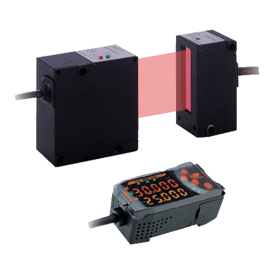
ZX-GT Series The ZX-GT Series Smart Sensors are a length measurement sensor using a CCD device. Position, dimensions, and other information can be stably measured by a line beam comprising a visible semiconductor laser and an optical scale on the CCD line sensor. -
Page 23: Part Names And Functions
This receives the laser light emitted from the laser emitter. (4) Connector This is the connector for connecting to the Controller. (5) Optical axis setting This indicator turns ON when the laser's optical axis is aligned in indicator the optical axis adjustment mode. Optical axis mode p.42 ZX-GT Series ZX-GT User’s Manual... - Page 24 Name Function (1) Input cable This is for connecting the Sensor receiver. (2) Voltage/Current This switch is for selecting voltage output or current output as the switch (on rear side) analog output. (default value: voltage output) Voltage/Current switch Voltage output Current output Output scaling settings are also required when switching the output.
-
Page 25: Function Settings
This indicator turns ON when bank 1 is selected. (2) Bank 2 indicator This indicator turns ON when bank 2 is selected. (3) Zero reset This indicator turns ON when the zero reset function is enabled. indicator This indicator lights when "the HIGH threshold < (4) Judgment output HIGH LED : the measured value."... -
Page 26: Communications With
PC or a PLC. (2) Controller connector This connector is for connecting the ZX-GTC Controllers. (3) Binary output cable This cable connects external devices such as a PLC so that measurement data is output in binary. -
Page 27: Mounting And Connecting Devices
Never look into the laser beam. Doing so continuously will result in visual impairment. Do not attempt to dismantle, pressurize, or incinerate the product. Doing so may cause the laser beam to leak, resulting in the danger of visual impairment. Important If a measurement target has a shiny surface, reflected light might adversely influence adjacent Sensors. - Page 28 Fix the Sensor onto the mounting base with M4 screws. 0 to 500 (mm) Tightening torque: 1.2 N•m Important For details on the positions of screw holes, check the external dimensions in "5 APPENDICES." • External dimensions p.131 • Adjusting the Optical Axis p.42 Integrated Type Fix the Sensor onto the mounting base with M3 screws.
-
Page 29: Mounting The Controller
Important Always hook the connector end of the Controller onto the DIN track first. Mounting strength may decrease if the I/O cable end is hooked onto the DIN track first. Push the Controller down onto the DIN track until the hook on the I/O cable side is locked. -
Page 30: Connecting Devices
Important Do not mount the Controller in such a way that a load is steadily applied on the connector, for example, with tension applied to the cables. Mounting and Connecting Devices... - Page 31 Controller.) sync wire sync wire Up to two extension cables can be connected. However, be sure to limit the total extension cable length between the receiver and the Controller to 30 meters (including the receiver cable). Wiring the Sensor (emitter)
- Page 32 • Use the blue wire (GND (0 V)) for the power supply, and the shielded wire sheath (analog GND) together with the black wire (analog output) for analog output. Connect analog GND to GND (0 V) even when analog output is not used.
- Page 33 Wiring the Interface Unit Output Cables Light blue GATE Red/white Black Yellow Brown Blue Pink Binary output Gray Green White Orange Purple Bright green Unused Assignments and Functions of Output Signal Wires p.93 Mounting and Connecting Devices ZX-GT User’s Manual...
- Page 34 Sensor (emitter) I/O Circuit Diagrams NPN type Controller (ZX-GT28E11) Brown 24 VDC Load Laser deterioration Orange alarm output 24 VDC Blue GND (0 V) Laser OFF input/ sync input Shielded Shield not connected internally PNP type Controller (ZX-GT28E41) Brown 24 VDC...
- Page 35 Important Make sure that the load connected to "analog output wire (co-axial) - analog GND wire" satisfies the rating of the set state (voltage or current output) before turning the Controller ON. Otherwise, the Controller may be damaged. NPN type Controller (ZX-GTC11)
- Page 36 Reset input Current output 4 to 20 mA Co-axial (black) Analog output Voltage/Current switch Voltage output Current output: 300 Ω or less ±4 V Load Output resistance Voltage output: 10 kΩ or more 100 Ω Co-axial (shield) Analog GND Yellow...
- Page 37 Interface Unit I/O Circuit Diagrams The following circuit configurations are used for data outputs (D0 to D11) and the total of 13 GATE signal outputs. NPN type Bright green Unused Light blue GATE Red/white D11 Black D10 Yellow D9 Brown D8...
- Page 38 PNP type Controller Brown 12 to 24 VDC Blue GND (0 V) Load Red/white D11 Black D10 Yellow D9 Brown D8 Blue Pink Gray Same as D0 circuit Same as D0 circuit Green D4 White D3 Orange D2 Purple D0...
-
Page 39: Connecting Controllers To Each Other
Connecting Controllers to Each Other Controllers are connected to each other via a Calculating Unit. The number of Controllers that can be connected to each other is as follows: • When calculating Controller measured values: three Controllers Calculation can be performed on two of these Controllers. -
Page 40: Connecting Interface Units
"CH1, CH2, CH3". Interface Unit Controller Note Cable clamp provided with the Controller The RS-232C cable can be fixed to devices, for example, using the cable clamp supplied with the Controller. Installation Removal Lift up the tab. Mounting and Connecting Devices... -
Page 41: Initializing Controller Settings
Important The settings of all banks and system settings are initialized regardless of the currently selected bank No. To save these settings, back them up to a personal computer using the SmartMonitor GT (ZX-GSW11) before performing initialization. Default States p.142 Initialize Controller settings. - Page 42 MEMO Initializing Controller Settings ZX-GT User’s Manual...
-
Page 43: Basic Operations
BASIC OPERATIONS S e t t i ng Me a s u r e m e nt C on di t i on s - F U N Mo d e Adjusting the Optical Axis and Registering the Standard Received Light Intensity... -
Page 44: Setting Measurement Conditions - Fun Mode
- FUN Mode Adjusting the Optical Axis and Registering the Standard Received Light Intensity When using an integrated Sensor, adjustment of the optical axis in step 3 is not required. Important Connect the Controller and Sensor sync wires. • Wiring the Sensor (emitter) p.29 •... - Page 45 Clean the emitter surface or remove object blocking light path. Note The received light waveform can be observed in more detail on the exclusive PC software (SmartMonitor GT (ZX-GSW11)). Register the standard received light intensity. Hold down for at least three seconds.
-
Page 46: Selecting The Measurement Mode
Select the measurement mode matched to your specific measurement requirements from the FUN mode menu. Specific Measurement Requirement and Measurement Mode Used p.50 The following describes, as an example, the basic operation procedure for measuring the outer diameter. Select the measurement mode. -
Page 47: Setting Thresholds - T Mode
Output ≤ HIGH threshold) PASS (ON when measured value < LOW threshold) Note In the special mode (IC lead pitch or IC lead width judgment mode), the following values are output: HIGH:Standard value setting LOW: Tolerance setting Measurement Cycle p.61 The following describes, as an example, the operation procedure for setting a HIGH threshold. -
Page 48: Functions And Operations During Operation
Present value Resolution In the IC lead pitch and IC lead width judgment modes, standard values and tolerances are displayed according to the threshold switch setting. In the IC lead pitch and IC lead width judgment modes, "0V" is displayed at all times. -
Page 49: Executing And Canceling A Zero Reset
Executing and Canceling a Zero Reset When the zero reset function is used, the measured value can be reset to a reference value of 0 when the ENT key is pressed or an external signal is input. Executing/Canceling a Zero Reset by External Signal Input p.126 When the Controller is turned OFF, all settings are cleared from memory (i.e. - Page 50 MEMO Functions and Operations during Operation - RUN Mode ZX-GT User’s Manual...
- Page 51 FUNCTION SETTINGS Settings Matched to Specific Measurement Requirements 50 Specific Measurement Requirement and Measurement Mode Used Explanation of Measurement Modes Adjusting Detection Conditions Measurement Cycle Number of Samples to Average Binary Level Edge Filter Setting Output Conditions Judgment output timing (timer)
-
Page 52: Settings Matched To Specific Measurement Requirements
Settings Matched to Specific Measurement Requirements Specific Measurement Requirement and Measurement Mode Used Mode Used Edge position Interrupted beam width measurement mode Regular positioning Incident beam width measurement mode Center position Center position measurement mode Position of round bar Thin wire position... - Page 53 The width up to the end of the first incident beam section is measured. p.58 The width from the top edge of the beam up to the center of the first and last edges of the measurement object is measured.
-
Page 54: Explanation Of Measurement Modes
How to select the measurement mode p.44 Note In cases such as the following, the width of the first incident beam section is measured from the side of the Sensor where the LED is located. This width is measured. Settings Matched to Specific Measurement Requirements... - Page 55 Note In cases such as the following, the width from the first edge up to the center of the first and last edges is measured from the side of the Sensor where the LED is located. This width is measured.
- Page 56 Description Range Number of IC leads (A) Set the number of IC leads of the measurement object. 2 to 14 (IC leads) IC lead pitch (B) Set the IC lead pitch to be used as the standard. 0.6 to 28 (mm)
- Page 57 1 to 14 object. (IC leads) IC lead width (B) Set the IC lead width to be used as the standard. 0.3 to 28 (mm) IC lead width tolerance Set the tolerance of the measured value with 0 to 28 (mm) respect to the reference value.
- Page 58 1 to 30, 49, 50 target. For details, see "How to count edge Nos." p.57 After selecting the measurement mode, make the following settings. Set the 1st edge. Change the selection. Confirm the selection. Set the 2nd edge. Change the selection.
- Page 59 - When "49" is set to one edge, be sure to set "50" to the other edge. - When "50" is set to one edge, be sure to set "1", "2" or "49" to the other edge. Settings Matched to Specific Measurement Requirements...
- Page 60 Wire Position Measurement Mode [THIN] This mode is for measuring thin wire of up to 0.1 mm in diameter. Measurement details are the same as those for the "center position measurement mode." How to select the measurement mode p.44 Glass Edge Measurement Mode [GLASS] This mode is for measuring the edge position of glass sheets.
- Page 61 Range: 0.00 to 599.99 (mm) Important When [WIDTH] is set, the range of the measured value becomes 0.00 to 599.99 mm. Note When three Controllers are connected to each other Set the expression on the Controller having the larger CH No.
- Page 62 The sub-display flashes. Move from one digit to another. Change the current value. Confirm the selection. Note Flow of measurement during calculation The value after averaging of each CH is calculated. Measurement processing Measurement processing Averaging Averaging 2-sensor operation processing Data of CH1 is acquired to execute calculation.
-
Page 63: Adjusting Detection Conditions
Adjusting Detection Conditions Measurement Cycle Normally, set the measurement cycle to the standard mode [NORM]. If the high-speed mode [FAST] is set, the measurement cycle speeds up but the Controller becomes more susceptible to the influence of ambient light. Setting value... -
Page 64: Number Of Samples To Average
Number of Samples to Average The average of the set number of samples can be output as the measured value. Set this function to disregard sudden changes in the waveform. Setting value Description 1, 2, 4, 8, 16, 32, 64, Setting the number of samples to average. -
Page 65: Binary Level
• Non-transparent object: 25% (default value) • Transparent object/non-transparent object: 50% or more Note When the measurement mode is the wire position measurement mode or the glass edge measurement mode, the binary level is automatically set to 50%. Important The edge detection state changes when the binary level is changed. -
Page 66: Edge Filter
Setting value Description 3 to 7 (pixels) Set the number of pixels to function as the edge filter. The setting differs according to the measurement mode. • When the wire position measurement mode or glass edge measurement mode is selected 3 to 7 (default value: 4) •... -
Page 67: Setting Output Conditions
LOW output OFF-D (OFF delay) After the judgment result has been confirmed, delays the time required for the PASS output to turn OFF by the time set to timer. (Also delays turning OFF the HIGH and LOW outputs.) Measured value... - Page 68 When the measured value changes from HIGH to PASS or from LOW to PASS, turns ON the PASS output with a pulse width equivalent to the time set to the timer. Neither the HIGH nor the LOW output are output.
-
Page 69: Hysteresis
Hysteresis Set the hysteresis width (difference between operation point and return point) for the upper and lower limits of the judgments if the HIGH, PASS, or LOW judgment is unstable near the threshold values. Hysteresis HIGH threshold Measured value Operation point... -
Page 70: Analog Output Conditions
With analog output, the relationship between the displayed measured value and output value can be freely set as the measurement result is converted to a current of 4 to 20 mA or a voltage of -5 to +5 V, and is then output. Match the settings to suit the connected external device. - Page 71 This section uses a current output as an example. Change the values in this example for voltage output as necessary. Switch the voltage/current switch to current output. Voltage output Important Be sure to perform the following with the Controller Current turned OFF.
- Page 72 If output scaling has not been set correctly, check the following points: • Is the measured value on the sub-display set to a value within the measuring range? (The content of zero reset or calculation is also reflected if set.) •...
- Page 73 Set scaling beforehand, and select current output or voltage output. Also, connect the analog output wire to an external ammeter or voltmeter. This section uses a current output as an example. Change the values in this example for voltage output as necessary.
- Page 74 Check that setting of correction values is completed. Setting Output Conditions ZX-GT User’s Manual...
-
Page 75: Setting Hold Functions
Setting Hold Functions Set hold conditions for measured values. The hold functions hold data for specific points, such as the minimum or maximum value, during the sampling period (sampling time), and output those values at the end of the sampling period. - Page 76 The difference between the minimum and maximum values is held. (Peak-to-peak hold) This option is selected mainly when detecting vibration. The output changes at the end of the sampling period, and is held until the end of the next sampling period. Max. value...
-
Page 77: Delay Hold
Delay Hold The delay time is set to ignore measured values immediately after the timing input. This is useful for avoiding bounding during device startup and the influence of machine vibration. The delay time (the delay between timing input and start of sampling) and the sampling period can be set. - Page 78 Set the delay hold. Change the selection. Confirm the selection. Set the delay time. Select [H-D-T]. The sub-display flashes. Move from one digit to another. Change the current value. Confirm the selection. Set the sampling time. Select [H-S-T]. The sub-display flashes.
-
Page 79: Changing Display Conditions
Changing Display Conditions Reversing the Display The main display and sub-display can be reversed, i.e., be turned upside down. Cursor key operations also will be reversed. This function is useful when the Controller is mounted upside down on a device. -
Page 80: Changing The Number Of Display Digits
Set the number of digits displayed on the main display and sub-display in the RUN mode. When four or less digits are set, the digits are disabled from the rightmost digit first. If 0 digits are set, all of the digital displays will go out. -
Page 81: Adjusting The Display Brightness (Eco Mode)
Adjusting the Display Brightness (ECO mode) When the ECO mode display function is used, the main display and sub-display are not lit, reducing current consumption. Setting value Description The main display and sub-display are lit at their regular brightness. (default value) The displays are not lit. -
Page 82: Setting Communication Conditions
RS-232C Communications Specifications Set the communication specifications for the Controller matched to the communications specifications of external devices. After setting the communications specifications, the Controller must be turned OFF then back ON again to enable the settings. Setting value Range... -
Page 83: Setting The Binary Output Cycle
Setting the Binary Output Cycle Set the cycle at which binary output is performed. After setting the binary output cycle, the Controller must be turned OFF then back ON again to enable the settings. Setting value Description 1 to 500 (ms) Set the output cycle. -
Page 84: Special Functions
The zero reset level is saved when the power is turned OFF. Important If zero reset memory is set to [ON], the zero reset level will be written in the Controller's non- volatile memory (EEPROM) each time a zero reset is performed. The EEPROM can be written a maximum of 100,000 times. -
Page 85: Display During A Zero Reset
Display during a Zero Reset Set the zero reset memory function to set the reference value to a value other than 0 (zero). Setting value Range 00.000 to 59.999 Set the reference value. (default value: 00.000) (mm) Select the special setting. -
Page 86: Key Lock
The key lock function disables all Controller keys. Once the keys have been disabled, no key input will be accepted until the lock is canceled. This function is useful for preventing inadvertent changes to settings. The mode and threshold switches are still enabled even when the key lock function is ON. -
Page 87: Switching Banks
Switching Banks The ZX-GT can hold up to two sets of settings, which are called a "bank". Banks can be switched from an external device when changing the device setup. Important The following data can be saved in memory as settings of banks. - Page 88 The currently selected bank can be switched to the other bank. Switching banks by operating the control keys When [KEY] is set as the source from where banks are to be switched, the banks can be switched by operating the control keys on the Controller.
-
Page 89: Displaying The System Version
Displays the Controller version. (default value) HEAD Displays the Sensor version. Select the version display. Select [INFO]. Change the selection. Confirm the selection. Check the version information. The version information for the selected item is displayed. Exit the version display. Special Functions ZX-GT User’s Manual... - Page 90 MEMO Special Functions ZX-GT User’s Manual...
- Page 91 COMMUNICATIONS WITH EXTERNAL DEVICES Output Data List Communications Using the Controller I/O Cable Using the Controller I/O Cable Binary Output Assignments and Functions of Output Signal Wires Output Format I/O Timing Charts RS-232C Communications on the RS-232C Interface Connecting External Devices...
-
Page 92: Output Data List
Calculations can be performed on up to two channels. One of the channels in the calculation is always CH1. One of the channels in the calculation is always fixed to CH1. Set the expression on the Controller having the larger CH No. -
Page 93: Communications Using The Controller I/O Cable
Setting analog output conditions p.68 In the IC lead pitch and IC lead width judgment modes, both the HIGH and LOW outputs turn ON when the judgment result is NG. In the IC lead pitch and IC lead width judgment modes, 0 V or 4 mA is output at all times. - Page 94 Cable color Signal Function Pink Bank switching input Bank 1 is selected when this input is OFF, and bank 2 is selected when this input is ON. Bank switching is enabled only when the bank switching source is set to "I-O".
-
Page 95: Binary Output
Binary Output Assignments and Functions of Output Signal Wires Measured values can be converted to 12-bit binary data and output on the Interface Unit output cables. Cable color Signal name Bit assignment Description Purple Binary data output signal wires Orange... -
Page 96: Output Format
Output Format Measured values and calculation values are converted to a 12-bit binary number (in the case of minus values, 2's complement) before they are output. Bit expressions are output using minus logic ("1" when open output is ON). The output cycle of binary output can be set on the Controller. -
Page 97: I/O Timing Charts
I/O Timing Charts This section explains the I/O signals that are exchanged between the Controller and external devices, and the timing charts for data output. Measurement cycle: Standard mode (NORM) Measurement timing 1 Measurement timing 2 Measurement timing 3 Controller judgment output... - Page 98 Analog output is started after the measured data is applied and the analog output response time (T3) elapses. Output is executed for the time specified as the binary output cycle after the IFU binary output response time (T4) elapses and the measured data is applied.
- Page 99 Important The minimum binary output cycle is 1 ms. Because the measurement cycle in the high-speed mode (FAST) is 0.5 ms, binary output from the Interface Unit is executed once every two measurements. The GATE signal turns ON for the predetermined time and measured data is captured on the external device after measured data is applied and the IFU binary output response time (T4) elapses.
- Page 100 Sampling When delay hold setting is ON Trigger input Sampling This is the time until the change in the ON/OFF state of the hold Trigger input response trigger is recognized as the trigger. time Standard mode (NORM): max. 2.0 ms High-speed mode (FAST): max.
- Page 101 Controllers x 0.3 ms + 1.8 ms Reset input Input the reset signal for at least 1 ms. After a reset input, output turns OFF "within the output response time x averaging number." (analog output maximum value: approx. 5 V/ approx.
-
Page 102: Communications On The Rs-232C Interface
By this method, command processing is executed when a command is sent to the Controller from an external device, and a response is returned to the external device from the Controller, when command processing ends. An error response is returned when the command sent from the external device is in error or when an error occurs during command processing on the Controller. -
Page 103: Connecting External Devices
First, connect the Interface Unit to the Controller. Connecting Interface Units p.38 Connecting a PC/PLC You can use the RS-232C connector of the Interface Unit to perform serial communication with a PC or PLC. Important When connecting to a PC or PLC, refer to the respective instruction manual. -
Page 104: About Communications Commands
"99" can be specified to target all channels only when the MEASURE command is issued. Response data Stores the acquired data. Delimiter This control code indicates the end of the data. Either CR or CR+LF is used. RS-232C ZX-GT User’s Manual... - Page 105 When processing fails Header Footer Header This control code indicates the end of the data. Use STX. Channel No. When multiple Controllers are connected to each other, the channel No. is specified in front of the command. (01 to 03) The default channel No.
- Page 106 Configuration of measured value data Acquired measured values are output as a data structure of variable length of up to 6 characters including the sign but excluding the delimiter. Delimiter Sign + integer: 6 digits (The measured value is prefixed with spaces for the number of insufficient data.)
-
Page 107: Setting Acquisition/Change Commands
BINLV Sets the binary level. p.108 Acquires the current binary level. p.108 EDGENUM Sets two edges whose width is to be obtained. p.109 Acquires the setting of current specified edges 1/2. p.110 HOLDMODE Sets the hold conditions. p.111 Acquires the current hold conditions. - Page 108 Bank Control Command Command name Description Reference BANK Switches the current bank. p.127 Acquires the current bank No. p.127 Utility Command Command name Description Reference DATAINIT Returns all Controller setup data to their defaults. p.128 RS-232C ZX-GT User’s Manual...
-
Page 109: Setting Acquisition/Change Commands
When processing fails < Explanation of parameters > Averaging number Specifies the number of samples to average. (1, 2, 4, 8, 16, 32, 64, 128, 256, 512, 1024, 2048, 4096) Acquiring the number of samples to average Acquires the current number of samples to average. - Page 110 B I N L V < Response format > When processing ends successfully Binary level (max. 2 digits) When processing fails < Explanation of parameters > Binary level The acquired binary level is returned. (25 to 90(%)) RS-232C ZX-GT User’s Manual...
- Page 111 < Response format > When processing ends successfully When processing fails < Explanation of parameters > Specified edge 1 No. Specifies the edge Nos. whose width is to be obtained. (1 to 30, 49, Specified edge 2 No. RS-232C ZX-GT User’s Manual...
- Page 112 < Response format > When processing ends successfully Edge No. (max. 2 digits) When processing fails < Explanation of parameters > Edge No. The edge No. of the acquired specified edge 1/2 is returned. (1 to 30, 49, 50) RS-232C ZX-GT User’s Manual...
- Page 113 Set/Acquire Hold Conditions < HOLDMODE command > Setting hold conditions Sets the hold conditions. < Command format > H O L D M O D E Hold conditions < Response format > When processing ends successfully When processing fails < Explanation of parameters >...
- Page 114 Acquiring hold conditions Acquires the current hold conditions. < Command format > H O L D M O D E < Response format > When processing ends successfully Hold conditions When processing fails < Explanation of parameters > Hold conditions The acquired hold conditions are returned.
- Page 115 When processing fails < Explanation of parameters > Hysteresis Specifies the hysteresis width. (0 to 59999) Note, however, that hysteresis can be set only by the value "HIGH threshold - LOW threshold" or less. Acquiring hysteresis Acquires the current hysteresis.
- Page 116 When processing fails < Explanation of parameters > HIGH threshold Specifies the judgment thresholds. (-19999 to 59999) Note, however, that judgment thresholds can be set only by the LOW threshold value "HIGH threshold - LOW threshold ≥ hysteresis". RS-232C ZX-GT User’s Manual...
- Page 117 Acquiring HIGH/LOW thresholds Acquires the current HIGH/LOW thresholds. < Command format > • HIGH threshold J U D P A R A • LOW threshold J U D P A R A < Response format > When processing ends successfully Threshold (max.
- Page 118 Switch/Acquire Measurement Mode < MEASMODE command > Switching the measurement mode Switches the current measurement mode. < Command format > M E A S M O D E Measurement mode < Response format > When processing ends successfully When processing fails <...
- Page 119 Acquiring the measurement mode Acquires the current measurement mode. < Command format > M E A S M O D E < Response format > When processing ends successfully Measurement mode When processing fails < Explanation of parameters > Measurement mode The acquired measurement mode is returned.
- Page 120 Set/Acquire Number of IC leads < PINNO command > This command is active only when the measurement mode is the IC lead pitch or IC lead width judgment mode. Setting the number of IC leads Sets the number of IC leads.
- Page 121 When processing fails < Explanation of parameters > Number of IC leads The acquired number of IC leads is returned. • IC lead pitch judgment mode (2 to 14) • IC lead width judgment mode (1 to 14) RS-232C ZX-GT User’s Manual...
- Page 122 Set/Acquire IC Lead Pitch/IC Lead Width Standard Values < REF command > This command is active only when the measurement mode is the IC lead pitch or IC lead width judgment mode. Setting standard values Sets the IC lead pitch/IC lead width standard values.
- Page 123 • IC lead width judgment mode (300 to 28000) Register Standard Received Light Intensity < TEACH command > Registers the all incident light state as the standard received light intensity. No parameters are provided for this command. < Command format >...
- Page 124 Set/Acquire IC Lead Pitch/IC Lead Width Tolerance Values < TOL command > This command is active only when the measurement mode is the IC lead pitch or IC lead width judgment mode. Setting tolerance Values Sets the IC lead pitch/IC lead width tolerance values.
-
Page 125: Measurement Control/Measured Value Acquisition
When processing fails < Explanation of parameters > Number of edges The acquired number of edges is returned as 2 bytes. (1 to 32) 10's digit 1's digit • The maximum number of edges that can be detected is 32. - Page 126 Note How to count edges Note that the edge count method differs from that in the specified edge measurement mode. Edge count method in the specified edge measurement mode p.57 The boundary between incident light and interrupted beam sections is counted as an edge.
- Page 127 Judgment result When processing fails < Explanation of parameters > Channel No. Specifies the channel No. to prefix the command when two or more Controllers are connected to each other. (Default is channel 1.) 01 to 03: Individual channels All channels Measured value/ The acquired measured value/judgment result is returned.
- Page 128 Execute/Cancel a Zero Reset < ZERO command > Executing a zero reset Executes a zero reset. No parameters are provided for this command. < Command format > Z E R O < Response format > When processing ends successfully When processing fails Canceling a zero reset Cancels a zero reset.
-
Page 129: Bank Control Command
When processing ends successfully When processing fails < Explanation of parameters > Bank No. Specifies the bank No. after the bank is switched. (1, 2) Acquiring the bank No. Acquires the current bank No. < Command format > B A N K <... -
Page 130: Utility Command
Utility Command Initialize Controller < DATAINIT command > Returns all Controller setup data to their defaults. No parameters are provided for this command. < Command format > D A T A I N I T < Response format > When processing ends successfully... - Page 131 Controller Calculating Unit Interface Unit Extension Cable Error Messages and Corrective Actions 140 Setup Errors Measurement Errors Standard Received Light Intensity Registration Errors 141 Default Values Basic Knowledge for Operation Reading Displays List of Key Operations Laser Safety Label Replacement...
-
Page 132: Specifications And External Dimensions
(with no icing or condensation) Ambient humidity Operating and storage: 35% to 85% (with no condensation) Vibration resistance (durability) 10 to 150 Hz Single-amplitude: 0.75 mm for 80 min each in X, Y and Z directions Degree of protection IEC60529 IP40... - Page 133 70%) Linearity is given to be a typical error with respect to an ideal straight line when the distance between the emitter and receiver is 100 mm and light is blocked at a distance of 50 mm from the receiver.
- Page 134 Integrated type: ZX-GT28S11/GT28S41 (Unit: mm) 2-M3 Mounting hole dimensions 2-3.2 mm dia. holes Laser ON indicator (green) Optical axis Five, 6.5 mm dia. countersunk holes, depth 5 Laser deterioration alarm indicator (red) Optical axis setting indicator (green) 54.1 17.8 7.15 20±0.1...
-
Page 135: Controller
Optical axis adjust mode/light intensity writing mode, variable binary level, functions variable edge filter, analog output scaling Calculation 2Possible on up to two Controllers (Calculation Unit ZX-CAL2 is required for connecting Controllers to each other.) A-B, A+B, width Other Measurement cycle setting, threshold setting, hysteresis setting, initialization,... - Page 136 Accessories Instruction Sheet The first response time is "measurement cycle x (number of samples to average setting + 1) + 1 ms" max. For the second response time onwards, the specified measurement cycle time is output. The response time in the high-speed mode (FAST) for the IC lead pitch and IC lead width judgment modes is 1 Current/voltage can be switched using the switch provided on the rear of the Controller.
-
Page 137: Calculating Unit
(with no icing or condensation) Ambient humidity Operating and storage: 35% to 85% (with no condensation) Vibration resistance 10 to 150 Hz Double-amplitude: 0.7 mm for 80 min each in X, Y and Z (durability) directions Shock resistance 300 m/s... -
Page 138: Interface Unit
(with no icing or condensation) Ambient humidity Operating and storage: 35 to 85% (with no condensation) Vibration resistance 10 to 150 Hz Single-amplitude: 0.35 mm for 80 min each in X, Y and Z (durability) directions Degree of protection IEC60529 IP20 Cable length RS-232C 0.5 m, binary output 2 m... - Page 139 (Unit: mm) 12.25 Connector 64.3 36.8 Round vinyl insulated cable 5.4 mm dia. (19/0.08 mm dia.) 15-core Round vinyl insulated cable 5.2 mm dia. (19/0.08 mm dia.) 10-core standard length 2 m standard length 0.3 m Specifications and External Dimensions...
-
Page 140: Extension Cable
External Dimensions ZX-XGC__A/XGC__R (Unit: mm) 54.1 L1 (Note 1) 51.5 15-pole connector (female) Round vinyl insulated cable, 15-core (Note 2) 15-pole connector (male) ) Note 1: ZX-XGC1A/R: 1M ZX-XGC2A/R: 2M ZX-XGC5A/R: 5M ZX-XGC8A/R: 8M ZX-XGC20A/R: 20M Note 2: Standard cable: 6.2 mm dia. - Page 141 GATE (IFU) ON/OFF These are not measured values in the IC lead pitch and IC lead width judgment modes. Voltage output: 0 V, current output: 4 mA Max. value: at voltage output, approx. 5.5 V, at current output, approx. 23 mA Specifications and External Dimensions ZX-GT User’s Manual...
-
Page 142: Error Messages And Corrective Actions
E-CHL There are two Sensors but only one Controller connected. p.37 • If two or more Controllers are connected to each other, turn OFF the power supply p.39 and check that the Controllers and Calculating Units are connected correctly. p.59 •... -
Page 143: Standard Received Light Intensity Registration Errors
Setting data is in error. p.39 • Hold the ENT key down for at least 3 seconds to initialize the settings data. • Replace the Controller if the above countermeasure does not solve the problem. Standard Received Light Intensity Registration Errors The following messages are displayed if correct received light intensity data cannot be obtained. -
Page 144: Default Values
Default Values The following table summarizes the default values of this Controller. Function Default Value Measurement cycle Standard mode (NORM) Measurement mode Interrupted beam width measurement Averaging number Hysteresis 00.100 Hold Judgment output timing (timer) OFF Special functions CLOSE Zero reset memory Zero reset 00.000... -
Page 145: Basic Knowledge For Operation
Basic Knowledge for Operation Reading Displays The data displayed on the main and sub-displays differs according to the currently selected mode. Alphabet Display Format List of Key Operations The functions of keys differ according to the currently selected mode. Description... -
Page 146: Laser Safety
Class 1 Class II Max. output 0.2 mW For products exported to the countries other than Japan and Europe, different safety standards are applied according to the countries. Check the LED safety regulations and standards of the relevant country. Label Replacement The warning label written in Japanese is affixed to the Sensor unit. - Page 147 FDA/laser emission port label ● Use in Countries Other than the U.S. For countries other than Japan and U.S., explanatory labels must be replaced by English ones (supplied with the product). When exporting to Europe, regulations differ as they must comply with EN60825.
-
Page 148: Summary Of Requirements To Manufactures
Specified wording required Service entry label Required as appropriate to the class of accessible radiation Override interlock label Required under certain conditions as appropriate to the class of laser used Wavelength range label Required for certain wavelength ranges LED label... - Page 149 Note: 1. This table is intended to provide a convenient summary of requirements. See text of this standard for complete requirements. 2. For the safety medical laser products, IEC 60601-2-22 applies 3. AEL: Accessible Emission Limit The maximum accessible emission level permitted within a particular class. For your reference, see ANSI Z136.1-1993, Section 2.
- Page 150 IIIa IIIb Performance (all laser products) Protective R (see note 2) R (see note 2) R (see note 2) R (see note 2) R (see note 2) R (see note 2) housing Safety interlock (see notes 3,4) (see notes 3,4)
- Page 151 Footnotes: Note 1: Based on highest level accessible during operation. Note 2: Required wherever & whenever human access to laser radiation above Class I limits is not needed for product to perform its function. Note 3: Required for protective housings opened during operation or maintenance, if human access thus gained is not always necessary when housing is open.
-
Page 152: Summary Of Requirements To User
1. This table is intended to provide a convenient summary of requirements. See text of this standard for complete precautions. 2. Class 1M laser products that failed condition 1 of table10 of the standard. Not required for Class 1M laser products that failed condition 2 of table10 of the standard. See the text for details. - Page 153 For U. S. A ANSI Z136.1:1993 “American National Standard for the Safe Use of Lasers” Control Measures for the Four Laser Classes Control measures Classification Engineering Controls Protective Housing (4.3.1) Without Protective Housing (4.3.1.1) LSO (see note 2) shall establish Alternate Controls Interlocks on Protective Housing ✰...
- Page 154 2. LSO: Laser Safety Officer An individual shall be designated the Laser Safety Officer with the authority and responsibility to monitor and enforce the control of laser hazards, and to effect the knowledgeable evaluation and control of laser hazards. For your reference, see ANSI Z136.1993, Section 1.3.
-
Page 155: Definitions Of Laser Classification
Note: Conditions for safe viewing of diffuse reflections for Class 3B visible lasers are: minimum viewing distance of 13 cm between screen and cornea and a maximum viewing time of 10 s. Other viewing conditions require a comparison of the diffuse reflection exposure with the MPE. -
Page 156: Compliance With Ec Directives
Safety category Low-Voltage EMC directive directive (*1) (*1) Compliance Exception Compliance For details of detailed compliance levels, we have issued the "Compliance with Declaration of Conformity: EN45014." Please contact your OMRON sales representative. Compliance with EC Directives ZX-GT User’s Manual... - Page 157 MEMO Compliance with EC Directives ZX-GT User’s Manual...
-
Page 158: Quick Reference For Displays
Interrupted beam width measurement mode Measurement mode Incident beam width p.50 measurement mode Outer diameter measurement mode 1, 2, 4, 8, 16, Center position measurement mode 32, 64, 128, Number of samples IC lead pitch judgment mode to average p.62... - Page 159 A+B mode A-B mode ■ Special function settings *1: When the mode is switched to the FUN mode, the optical axis adjustment mode will be displayed first. *2: When two or more Controllers are connected to each other, this is displayed on the Controller whose Function OFF channel No.
- Page 160 ● When [ETC] is selected: ● When [DISP] is selected: Zero reset memory Display reverse p.77 p.82 Display during zero reset ECO mode p.83 p.79 Returns to (version display). Number of display digits ● When [IFU] is selected: p.78 p.80 Returns to (version display).
- Page 161 Resolution Present value *1: In the IC lead pitch and IC lead width judgment modes, standard values and tolerances are displayed according to the threshold switch setting. *2: In the IC lead pitch and IC lead width judgment modes, "0V" is displayed at all times.
- Page 162 MEMO Quick Reference for Displays ZX-GT User’s Manual...
-
Page 163: Index
DATAINIT command Change of device setup Default Values Binary Level Delay Hold Binary output cable Delay Time Binary Output Cycle Display during a Zero Reset Binary output indicator Displaying the System BINLV command Version Bottom hold Edge Filter Calculating the Measurement... - Page 164 OFF delay HYS Command ON delay Hysteresis One-shot Operation Step Guide Optical axis adjustment Optical axis setting indicator IC Lead Pitch Judgment Mode 54 Outer Diameter Measurement IC Lead Width Judgment Mode Mode Output cable Incident Beam Width Output Data...
- Page 165 Connector Indicator Specifications Zero Reset Memory RUN Mode 46, 159 Sample hold Sampling Time Sensor External dimensions I/O Circuit Diagrams Mounting Parts Names and Functions Specifications Wiring (emitter) Setting Acquisition/Change Commands Setting hold conditions Setting the Bank Switching Source Specified Edge Measurement...
-
Page 166: Revision History
Revision History A manual revision code appears as a suffix to the catalog number at the bottom of the front and back covers of this manual. Z263-E1-01 Cat. No. Revision code Revision code Revision date Revised content June 2007 Original production Revision History ZX-GT User’s Manual...
Need help?
Do you have a question about the ZX-GT and is the answer not in the manual?
Questions and answers