Table of Contents
Advertisement
Quick Links
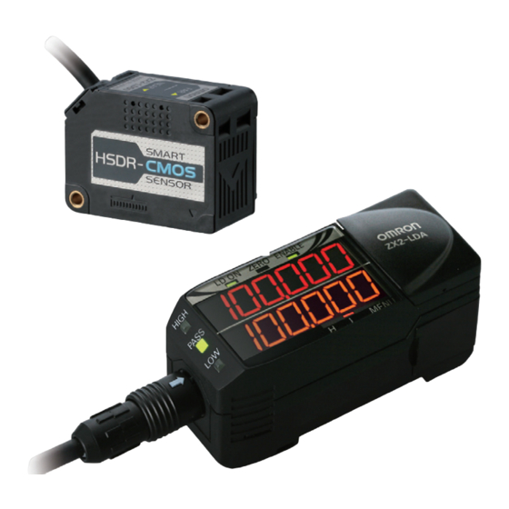
Smart Sensors Laser Sensors CMOS Type
ZX2
Stable measurement that is unaffected by
workpiece changes.
The simple setting for everyone.
• High-precision measurement to approx. 10 μm.
• Stable measurement regardless of movement or changes in
workpiece color or material.
• Smart tuning for optimal setting with one button for essentially any user.
• The 11-segment display enables reading characters at a glance.
• Four built-in banks make changeovers easy.
• Stable measurement in harsh environments with IP67
protection for Sensor Head and robot cable.
• Laser life indicator to prevent line stoppage through visualization.
Be sure to read Safety Precautions on page 11
Features
Stability
Measurements to a Precision in the Order of 10 µm for any Workpiece
Stable measurement even for changes in colors and materials or for moving
workpieces with CMOS that has a dynamic range of two million times
The use of a unique OMRON HSDR-CMOS (high-speed and dynamic range) image sensor
and a step-less laser power adjustment algorithm enable stable measurements for any
color or surface conditions, from metals to substrates, rubber, and transparent objects.
Linearity of 0.05% F.S.* achieves a measurement precision in the order of 10 µm.
Stable measurements on objects with changing color/material
e measurements on objects with cha
Measurements for Bright Workpieces
Small
Small
CMO
CMOS shutter time
Laser emission power
Laser e
Weak
Weak
T
Two-element
autom
automatic adjustment
Shinny metals
Shinny metals
The light int
The light intake amount remains
g
the same even if the workpiece changes.
the same even
Light
intake
amount
Shinny metals Black rubber
Linearity characteristic of
existing product according to material
1
0.8
0.6
0.4
0.2
0
-0.2
-0.4
White ceramic
SUS304, hairline (parallel)
-0.6
SUS304, mirror finishing
Black rubber
-0.6
SUS304, hairline (orthogonal)
-1
0
2
4
6
8
10
-10
-8
-6
-4
-2
Distance (mm)
Stable measurements on moving objects
A line beam is used in addition to an emitter beam when dealing with rough surfaces to average out the
amount of reflected light and to offset the amount of light received at a high-speed measurement period of
30 µs in order to reduce variations in received light and to enable stable measurements for moving objects.
Limit of resolution of
existing product when workpiece is moving
400
Workpiece:SUS304, hairline (parallel)
300
200
Max error: approx.400µm
100
0
-100
-200
-300
-400
Rest state
Moving condition
workpiece
* Linearity: The maximum error that occurs for measurements within the measurement range.
A linearity of ±0.05% F.S. means that when the LD50L is used for a measurement range of 40 to 50 mm,
the maximum error within the measurement range will be 10 µm.
PAT.P
color/material
Measurements for Dark Workpieces
Large
Large
L
ter tim
me
on power
Strong
Strong
ment
justment
Black rubb
Black rubber
mount remains
orkpiece changes
Linearity characteristic of
the ZX2 according to material
1
No Variation
0.8
for Different
0.6
Workpieces
0.4
0.2
0
-0.2
-0.4
White ceramic
SUS304, hairline (parallel)
-0.6
SUS304, mirror finishing
Black rubber
-0.6
SUS304, hairline (orthogonal)
-1
-10
-8
-6
-4
-2
0
2
4
6
8
10
Distance (mm)
Limit of resolution of
the ZX2 when workpiece is moving
40
No Variation
Workpiece:SUS304, hairline (parallel)
30
for Moving
20
Max error:
Workpieces
10
approx.7µm
0
-10
-20
-30
-40
Rest state
Moving condition
workpiece
Для заказов: +7(499)707-11-20,
8-800-511-65-88(Бесплатно по РФ)
For the most recent information on models that have been certified for
safety standards, refer to your OMRON website.
Easy
Essentially Anyone Can Set Optimum Conditions
Easily select smart tuning
with one button.
The optimum settings for stable measurement can be achieved with one
smart tuning button. The settings will not rely on the skill of the user.
Sensor configuration by just a pushing
the SMART button
Three selectable tunings
More accurate settings are made possible by the three tuning
methods for different workpiece types and surface conditions.
Scene.1
Scene.2
One type of workpiece
Multi-smart tuning
Single smart tuning
Ideal configuration for stable detection
Best configuration for stable detection
of changing objects by pushing the
in case of objects do not change by
button for three seconds
pushing the button for one second
Scene.3
Surface conditions
of the workpiece are variable
Active smart tuning
Continuous configuration improvement
for the stable detection of all locations
by pushing the button for five seconds
Email: i@sp-t.ru
PAT.P
Several types of workpiece
1
Advertisement
Table of Contents

Subscribe to Our Youtube Channel
Related Manuals for Omron ZX2


Summary of Contents for Omron ZX2
- Page 1 CMOS that has a dynamic range of two million times with one button. The use of a unique OMRON HSDR-CMOS (high-speed and dynamic range) image sensor The optimum settings for stable measurement can be achieved with one and a step-less laser power adjustment algorithm enable stable measurements for any smart tuning button. The settings will not rely on the skill of the user.
- Page 2 Ordering Information Units Sensor Heads [Dimensions➜ page 11] Appearance Sensing method Beam shape Sensing distance Resolution Model Line beam ZX2-LD50L 0.5M 50±10 mm 1.5 μm Diffuse reflection type Spot beam ZX2-LD50 0.5M Diffuse- reflective Line beam ZX2-LD100L 0.5M 100±35 mm 5 μm...
-
Page 3: Sensor Head
0.02% F.S./°C* is realized. * If the room temperature varies 1°C, the measured value varies 0.02% F.S. (corresponding to 4µm for the Model ZX2-LD50) Compact sensor for easy mounting World smallest* The world’s smallest CMOS laser displacement sensor... - Page 4 An 11 segment LED display is integrated The 7 segment display The 11 segment display in the compact housing. Alphanumeric on existing models on model ZX2 characters can be read with ease and there is no need to refer to a manual. 30mm 30mm...
-
Page 5: Specifications
Resolution performance may not be satisfied in a strong electromagnetic field. *3. Linearity: indicates the error with respect to the ideal straight line of the displacement output in the case of measuring Omron’ s standard target object. Linearity and measured value may vary depending on target object. - Page 6 *2. Select current output (4 to 20 mA) and voltage output (±5V or 1 to 5V) by MENU mode. *3. Calculating unit (ZX2-CAL) is necessary. Calculations are possible for up to two amplifier units. Mutual interference prevention is possible for up to five amplifier units.
-
Page 7: Engineering Data (Reference Value)
Angle Characteristic The angle characteristic is a plot of the inclination of the sensing object in the measurement range and the maximum value of the error to analog output. Note: SUS304 = Stainless steel SUS304 ZX2-LD50 Side-to-side Inclination Front-to-back Inclination... -
Page 8: Linearity Characteristic For Different Materials
Linearity Characteristic for Different Materials ZX2-LD50 −50° Inclination Front-to-back +50° Inclination 0° Inclination White ceramic White ceramic White ceramic SUS304, mirror finish SUS304, mirror finish SUS304, mirror finish Black rubber Black rubber Black rubber 0° Inclination +50° Inclination −50° Inclination −0.2... - Page 9 Angle Characteristic ZX2-LD50V Side-to-side Inclination for Flat Mirror Front-to-back Inclination for Flat Mirror Side-to-side Inclination for Silicon Wafer -1.0° 0.5° -1.0° 0.5° -1.0° 0.5° -0.5° 1.0° -0.5° 1.0° -0.5° 1.0° 10.5° 0° 0° 0° + Inclination + Inclination + Inclination...
-
Page 10: I/O Circuit Diagrams
* Measurement distance displayed by the amplifier unit. The measurement distance displayed by the amplifier unit takes the measurement center distance as 0, and the NEAR and FAR sides from the sensor are displayed by + and −, respectively. I/O Circuit Diagrams NPN Amplifier Unit (ZX2-LDA11) PNP Amplifier Unit (ZX2-LDA41) Brown: 10 to 30 VDC... - Page 11 (16.5 dia., 29.8 Vinyl insulated round robot cable, 4.7 dia., 4 conductors length: 30 mm) to the * In the case of ZX2-LD50 (L), L=50, A=21 ° (Conductor cross-section: 0.086 mm /Insulator diameter: 0.9 mm) cable within 100 mm In the case of ZX2-LD100 (L), L=100, A=11.5 °...
- Page 12 (ZX2-XC20R: 5.1 dia.) 14.4 * Length L is as follows. ZX2-XC1R: 1 m, ZX2-XC4R: 4 m, ZX2-XC9R: 9 m, ZX2-XC20R: 20 m 36.7 Minimum bending radius: 30 mm Note: Attach the enclosed ferrite cores (16.5 dia., length: 30 mm) within 100 mm of each end of the extension cable.
-
Page 13: Mounting Bracket
Nut plate: 1 (26.4) (26.4) 16.8 16.8 Use this Mounting Bracket when installing the ZX2-LD100 (L) as a normal Diffuse-reflective or Regular-reflective Sensor Head. Installation Method for Regular-reflective Sensor Installation Method for Regular-reflective Sensor Head Heads (Installing a Diffuse-reflective Sensor... - Page 14 ±0.05 1 The measurement distance reference position is the Sensor’s sensing surface. ZX2-LD50 (L): 50 ZX2-LD100 (L): 100 Note: When securing the Sensor Head in the Mounting Bracket, insert the screws into the side of the Sensor Head where the warning label is located and secure the Sensor Head into place.
Need help?
Do you have a question about the ZX2 and is the answer not in the manual?
Questions and answers