Advertisement
Smart Sensor High precision contact type ZX-T Series
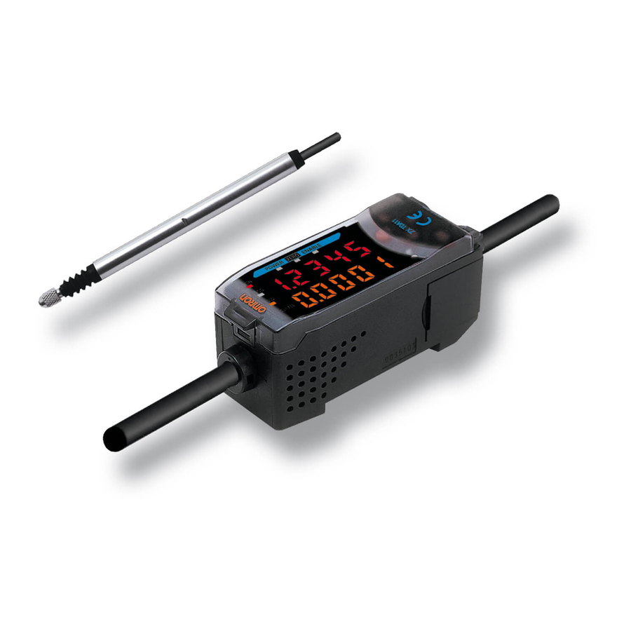
ZX-T Series
Ordering Information
Sensors
Sensor Heads
Size
6 dia.
Short type
6 dia.
Standard type
6 dia.
Low measurement type
Note: The resolution refers to the minimum value that can be read when a ZX-TDA@1 Amplifier Unit is connected.
Amplifier Units
Appearance
Accessories (Order Separately)
Calculating Unit
Appearance
ZX-T Series
Type
Sensing distance
1 mm
4 mm
4 mm
Power supply
DC
Model
ZX-CAL2
Resolution (See note.)
0.1 µm
0.1 µm
0.1 µm
Output type
NPN
ZX-TDA11
PNP
ZX-TDA41
ZX-series Communicationys Interface Unit
Appearance
Model
ZX-TDS01T
ZX-TDS04T
ZX-TDS04T-L
Model
Model
ZX-SF11
B-77
Advertisement
Table of Contents

Subscribe to Our Youtube Channel
Related Manuals for Omron ZX-T


Summary of Contents for Omron ZX-T
-
Page 1: Ordering Information
4 mm ZX-TDS04T 0.1 µm 6 dia. Low measurement type 4 mm ZX-TDS04T-L Note: The resolution refers to the minimum value that can be read when a ZX-TDA@1 Amplifier Unit is connected. Amplifier Units Appearance Power supply Output type Model ZX-TDA11... -
Page 2: Specifications
Instruction manual, Preamplifier Mounting Brackets (ZX-XBT1) Note 1. The resolution is given as the minimum value that can be read when a ZX-TDA@1 Amplifier Unit is connected. This value is taken 15 min- utes after turning ON the power with the average number of operations set to 256. -
Page 3: Characteristic Data
+0.5 mm Displacement (−2 mm) (+2 mm) High/Low output Note: To prevent destroying the Sensor Head, both the high and low judgment outputs will light if 101% of the upper limit of the measurement distance is reached. ZX-T Series B-79... -
Page 4: Amplifier Unit
LOW judgement output ground. Black Linear output Shield 3. The blue line (0 V) is the 0 V power supply line. The shield Linear output GND Pink wire (linear output GND) is used together with the black line Judgement output hold input Orange (linear output) to connect the linear output. - Page 5 Two, 3.5 dia. Mounting with 3-point Support Mounting jig Supported at 60° Mounting width: 3 points 8 mm min. Tightening torque: 0.6 to 0.8 N·m (M3 screws) Material: Aluminum Tightening force: 100 N max. Sensor Head Base jig cross-section ZX-T Series...
- Page 6 • Measurements may not be possible or may not be accurate for some materials and shapes. • The Sensor will be destroyed if the Actuator is pressed too far. Do not use the Actuator past the point where a pressing force alarm (OVER) is displayed.
- Page 7 Wiring • Cable Extension Do not extend the cable for the Sensor and the Amplifier Unit to a • Wiring Check length exceeding 10 m. Use a ZX-XC@A Extension Cable (sold sep- After wiring is completed, before turning ON the power, confirm that arately) to extend the Sensor’s cable.
- Page 8 Material: Stainless steel ALL DIMENSIONS SHOWN ARE IN MILLIMETERS. To convert millimeters into inches, multiply by 0.03937. To convert grams into ounces, multiply by 0.03527. Cat. No. E345-E2-02-X In the interest of product improvement, specifications are subject to change without notice.
Need help?
Do you have a question about the ZX-T and is the answer not in the manual?
Questions and answers