Table of Contents
Advertisement
Advertisement
Table of Contents

Summary of Contents for Veeco MS40
-
Page 2: Table Of Contents
Table Of Contents Section 1: General Information Introduction Unpacking & Inspection Installation Features & Specifications General Description 1-11 Section 2: Operating the MS-40 Introduction Operator Controls & Indicators Starting the MS-40 Leak Detector 2-19 Leak Testing 2-20 Operation With an External Pump 2-22 Shut Down Procedure 2-25... - Page 3 Contamination of the Vacuum System Venting the Vacuum System 4-11 Cleaning Requirements 4-12 Calibration Requirements 4-19 General Service & Repair 4-21 4.10 Troubleshooting Aids 4-32 Section 5: Parts List Introduction Recommended Spare Parts for the MS-40 Other Components Appendix A: Glossary of Terms Used in Leak Detection Appendix B: A.V.S.
-
Page 4: Section 1: General Information
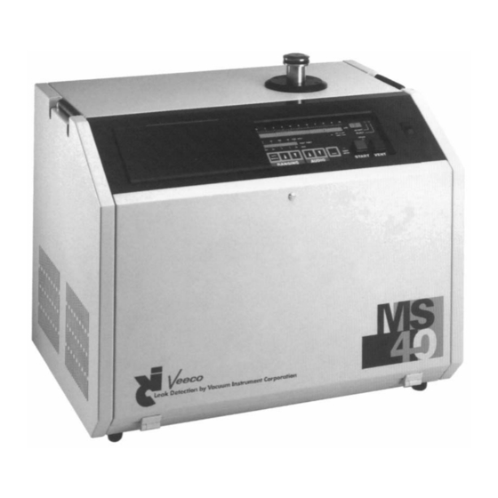
General Information Introduction This Operations & Maintenance Manual describes in detail the information needed to understand the operation and functions of the VIC MS-40 Fully Automatic Portable Leak Detector (illustrated in Figure 1-1), and provides the information needed to service and maintain the unit in optimal working condition. - Page 5 Figure 1-1 VIC Model MS-40 Portable Automatic Leak Detector 1109-186-00 Rev. C...
-
Page 6: 1.2 Unpacking & Inspection
Chapter 4, Service & Maintenance, describes in further detail the unit’s Service Mode, the necessary tuning/calibration procedures for the MS-40, required periodic service procedures and recommended service intervals, detection and correction of contamination within the vacuum system, procedures for venting the vacuum system, cleaning requirements and procedures, calibration of measurement components, valve block service and repair, repair/replacement of the unit’s electronics and a full listing of front panel error codes, their probable causes and our recommended corrective... - Page 7 the back panel must be opened. Both panels are hinged at the bottom and held with a single screw at the top of each panel. To open a panel, loosen the captive screw at the top of the panel (a 1/4 turn is sufficient to unloosen the screw) and gently lower the door.
- Page 8 To fill the pump with oil, unscrew the black cap to the right of the exhaust filter. Using the oil (1990-924-00) and the funnel (1331-191-00) provided in the installation kit, slowly fill the pump until the level in the sight glass is approximately 1/4”...
- Page 9 FIGURE 1 - 2 INTERNAL ROTARY VANE MECHANICAL PUMP 1109-186-00 Rev. C...
-
Page 10: Installation
Installation The MS-40 has been designed as a completely self-contained portable leak detector and therefore has the capability to work in a wide range of environments. However, before installation in a work area, certain requirements must be met. • A properly grounded electrical supply (115V/60Hz/10A, 230-240V/50Hz/5A, 100V/50Hz/10A, or 100V/60Hz/10A as labeled on rear of unit) must be available for the unit. -
Page 11: 1.4 Features & Specifications
1.4 Features & Specifications FEATURES Sensitivity: 4 x 10 std cc/sec air equivalent Leak Rate Range: 10 to 4 x 10 std cc/sec air equivalent (with optional external pump) 10 x 10 to 4 x 10 std cc/sec air equivalent (without external pump) Start-Up: Fully functional in less than 3 minutes. - Page 12 Ranging: Without an external roughing pump, begins at the [Automatic/Standard least sensitive gross range (10 ). The unit ranges Mode] downward until a leak is detected or until it reaches its most sensitive range (10 ). With the optional external pump, if a gross leak is detected, the unit ranges up to the appropriate decade.
- Page 13 Noise & Drift: <4% on 10 range Testable Masses: 3 and 4 Maximum 10 x 10 std cc/sec air equivalent (without external Measurable Leak: pump) 10 std cc/sec air equivalent (with optional external pump) Maximum Inlet Gross Mode: Atm (with optional external pump) Pressure: Reverse Mode: 7.5 Torr Direct Mode: 100 mTorr...
-
Page 14: General Description
General Description The MS-40 is a fully automatic, dual mode, turbo-molecular pumped portable leak detector. Each of its two modes (Reverse Flow or Direct Flow) is automatically selected by the leak detector based on the currently selected leak rate range. Reverse Flow Mode permits rapid testing for leaks in test objects that are characterized by a high degree of out-gassing. - Page 15 1.5.1 Standard Operation This is the normal operating mode for the MS-40. During operation, the User need only use the right (uncovered) portion of the display panel (the User Panel is illustrated in Figure 2-1). All functions to be accessed and display information needed to leak test an object are found on this panel.
- Page 16 Grouped to the right of the Service Mode Indicator are a series of LED indicators. The Service Mode allows the setting of the unit’s Amplifier Gain, Anode Voltage, Calibration Temperature and Internal Calibration Value in conjunction with the arrow buttons and LED alphanumeric display to the right of the indicators.
-
Page 18: Section 2: Operating The
Operating The MS-40 Introduction This chapter contains the information needed by the user to operate the MS-40 Leak Detector and perform leak checks on a test object. This chapter is grouped into three general sections: 1 Operator Controls & Indicators 2 Starting &... - Page 19 1109-186-00 Rev. C...
-
Page 20: Operator Controls & Indicators
Operator Controls & Indicators The following Controls & Indicators are located on the User Panel at the top right front of the unit. Items are listed from left to right, top to bottom (see Figure 2-1 for an illustration of the User Panel). LEAK RATE BAR GRAPH An LED bar graph indicating the mantissa of the measured leak rate of the test object. - Page 21 REJECT During leak testing, this indicator will illuminate when the leak measured is greater than or equal to the programmed reject rate (or maximum acceptable leak rate). The reject rate is set by the user from the Service Panel (see Section 2.7). READY When lit, the unit is in standby mode (all valves except the Fore-line valve are closed).
- Page 22 ZERO In Standard Mode, The ZERO momentary switch is active only during actual leak testing. When pressed, this unit’s computer reduces the measured leak rate displayed by the unit. To zero within the decade being measured (e.g., a 4 x 10 cc/sec leak rate would now be displayed as a 0 x 10 cc/sec leak rate).
- Page 23 VENT Dual function pushbutton. When pressed momentarily, the MS-40 is interrupted from its current testing cycle and placed in standby (wait) mode. The green READY indicator will light. When pressed and held for a preprogrammed time (as programmed by the user; factory default is 0.5 second) the pushbutton initiates an AUTO-VENT cycle and returns the test port to atmospheric pressure.
- Page 24 Service or Standard Modes. Note that G1, G4 and G5 are not controlled by the MS-40 and must be set by the user. G1 may be set by the user when the MS-40 is leak testing in the Gross Mode, or when the unit is in the service mode. G4 and G5 can be set when the unit is in sniff testing mode.
- Page 25 CROSSOVER 1 The alphanumeric display indicates the programmed test port pressure needed to crossover from the unit’s gross testing mode to reverse testing mode (when using the optional external pump). If an external pump is not connected to the unit, the crossover set point is the pressure needed to crossover from the unit’s roughing mode to the reverse testing mode.
- Page 26 D3/Vent Delay: The amount of time needed to hold the VENT pushbutton before the venting cycle begins. The factory default is 1.0 seconds; the parameter may be set between 0.1 to 999.9 seconds. D4/Vent Duration: The amount of time the vent valve will stay open after the unit’s Pirani gauge indicates atmosphere has been reached.
- Page 27 range electrical offset; expressed as a fraction of a volt (e.g., 0.00xx). range electrical offset; expressed as a fraction of a volt (e.g., 0.00xx). Same as in Standard mode Same as in Standard mode Same as in Standard mode EMISSION Emission Current.
- Page 28 HIGH VACUUM The alphanumeric display indicates pressure in the high- vacuum section (the area surrounding the filament within the spectrometer housing). If the unit’s filament has been turned off, the display will state OFF, otherwise the display indicates the high vacuum pressure in either Torr or bar. The selection of units to be displayed is made by a blue toggle switch located underneath the Service Panel.
- Page 29 TEST PORT Test Port Pressure. The alphanumeric display indicates the pressure of the test port. May be displayed in millitorr or millibar. The selection of units to be displayed is made by a blue toggle switch located underneath the Service Panel. The switch is accessed by opening the front panel and is mounted on the circuit board located directly under the Service Panel.
- Page 30 FIL ON/OFF Filament ON/OFF. Momentary switch. When the unit is in Service Mode, pressing this switch will toggle the active filament on or off. When the unit is in Standard Mode, this switch also toggles the active filament on or off. However, whenever the unit is in Standard Mode, the filament may be turned on only when the high-vacuum section has been sufficiently evacuated (as determined by the MS-40’s computer).
- Page 31 CAL CHECK Calibration-Check. Momentary Switch. Active only in Standard Mode. Pressing this switch allows the user to initiate the unit’s Calibration-Check sequence in conjunction with the MS-40 internal calibrator. See Section 2.9 for a full description of the Calibration-Check function. Calibrate.
- Page 32 1109-186-00 Rev. C 2-15...
- Page 33 The connectors that are listed below allow the MS-40 to interface with various external equipment. An illustration of these rear panel connectors is presented in Figure 2-2. All of the connectors are located on the rear of the unit, below the rear panel (from left to right): SNIFFER CONNECTOR This port (a quick-connect fitting is attached to the port) is...
- Page 34 HAND-HELD REMOTE PORT Allows the handheld remote control to operate the MS-40. Most of the features of the user Control Panel are also on the remote control. Specifically, the remote control has an LED bar graph and numeric display indicating the measured leak rate of the test object, switches to select between Auto/Manual ranging, up/down arrow keys for use during manual ranging, a START button as well as a VENT button.
- Page 35 Figure 2-3 MS-40 Hand Held Remote Control 1109-186-00 Rev. C 2-18...
-
Page 36: Starting The Ms-40 Leak Detector
Starting the MS-40 Leak Detector The MS-40 is started from the User Panel simply by pressing the ON/OFF (I/O) switch. During the three-minute Start-up mode, the following will occur within the unit: The unit will activate a self-diagnostic routine. The fore-line area will be pumped down. The turbo-molecular pump will spin up to its rated speed. -
Page 37: Leak Testing
Leak Testing Leak testing is most often performed on the MS-40 by connecting a test object to the leak detector test port. The unit’s leak detector test port is located on the top right of the MS-40 s housing. Vacuum Testing: Through the use of the detector’s internal rough pump (and external rough pump, if so equipped) the test object is evacuated. - Page 38 If a vacuum testing procedure is underway, spraying of the test object with helium should now commence. Leak testing begins in the 10 std cc/sec range. The unit will continue to search for a leak, ranging downward until it reaches the 10 std cc/sec range.
-
Page 39: Operation With An External Pump
Operation With an External Pump Connect the test object to the test port. Press the green START pushbutton. The external rough valve opens and the test object is evacuated. As soon as roughing has commenced, the gross valve opens. Leak testing begins in the 10 std cc/sec range. - Page 40 Sniff Testing: Sniff Testing is performed by checking for escaping helium in a test object already filled with helium gas. Sniff testing is unique in that: Leak detection is performed through a small orifice (a sniffer probe) that is attached to tubing that is then connected to the leak detector, and the test object itself is not evacuated during testing.
- Page 41 High Sensitivity Sniff Testing High Sensitivity Sniff Testing is similar to the sniff testing procedure (above) except: The sniffer probe is connected to the top test port instead of a dedicated “sniff” port on the back of the machine. Provides for greater sensitivity during testing. Operates in Reverse flow mode rather than the Sniffing mode.
-
Page 42: Shut Down Procedure
Shut Down Procedure The MS-40 may be shut down at any time by pressing the on/off (I/O) switch to the off (O) position. The unit automatically ensures that the vacuum system and system electronics are properly powered down. Turn off all peripheral equipment (i.e., external rough pump, printer, etc.). - Page 43 (mTorr) or millibar. One mTorr is equal to 1 x 10 Torr. One millibar (mbar) is equal to 1 x 10 bar. To alter the Crossover 1 set point, press either of the “SET” arrow keys. The alphanumeric display will change either down or up in correspondence with the number of key presses of the left or right arrow keys.
- Page 44 Setting the Accept/Reject Point The Accept/Reject set point is the designated leak rate value that indicates whether or not the leak rate of the test object meets or fails a predefined maximum leak rate standard. For example, if the accept/reject set point has been set to 5 x 10 std cc/sec, any test object that has a leak rate of less than 5 x 10...
- Page 45 1109-186-00 Rev. C 2-28...
- Page 46 system valves. Also displayed in the schematic are the user-adjustable time delays of the rough, fine and vent valves and how they impact the test cycle. The ways in which delay settings may be used to benefit certain testing conditions are described below: D1/Fine Crossover Delay: Occurs after Crossover 2 has been reached and refers to the delay (in seconds) between the attainment of Crossover 2 and the onset of Direct testing (the opening of the Fine valve).
- Page 47 D4/Vent Duration: Vent Duration refers to the amount of time (in seconds) that the Vent valve will remain open. D4 is adjustable between 0.1 to 999.9 seconds (the factory default setting is 1.0 second) allowing the operator to optimize the venting of a particular test object. D5/Minimum Gross Testing Time: Sets the minimum amount of time that the MS-40 will remain in the Gross test mode.
-
Page 48: Setting Additional Parameters
To display D2 through D7, continue pressing the same SELECT momentary switch; the indicator light will not move to the next function (in this case, EMISSION) until all seven delay parameters have been cycled. When the desired delay parameter appears in the alphanumeric display, it can be adjusted as in Step 3. -
Page 49: Test Aids & Procedures
G2 and G3 are normally set by the unit’s computer so it may properly calibrate the unit. When in Service mode, if the operator changes the gain, the calibration will no longer be correct. However, G4 and G5 are always set by the user. Anode Voltage Displays the anode voltage of the mass spectrometer source. - Page 50 Auto Zero The “Auto-Zero” or “Zero” feature, activated from the User Panel, allows the operator to test with the presence of residual helium. Pressing the ZERO button will cancel out the measurement of any helium present in the vacuum system or test object (the unit will display the amount of helium above the “zeroed out”...
- Page 51 Calibration Check (Cal-Check) Cal-Check is the feature that allows the user to verify the measurement accuracy of the MS-40 leak detector. The unit automatically connects the internal leak rate standard of the unit to the test port, measures the internal calibrator, subtracts the background helium measurement and displays the results on the Leak Rate Bar Graph located on the User Panel.
- Page 52 Calibration (Cal) Pressing the CAL momentary switch activates the Calibration function. The Calibration function of the leak detector is available only after the Cal-Check procedure has been completed. After the Cal-Check cycle is completed, when the actual leak rate measured by the unit is close to, but not exactly the same as the internal leak rate standard, the Calibration function may be used.
-
Page 54: Section 3: Theory Of Operation
Theory Of Operation Introduction: Leak Detection Theory When designing and manufacturing systems that contain gases or fluids, or systems that are normally evacuated, the manufacturer or tester must take into account the degree of leakage that can occur. To qualify these products, various methods may be selected to test these products for leaks. - Page 55 • To prevent the loss of contained gases or liquids • To prevent hazards caused by escaping toxic materials • To prevent contamination due to materials leaking from or leaking into an object • To test the projected reliability of sealed systems or the components within the systems.
- Page 56 • System failure during the operational life of the system • Hazards to personnel and equipment when leaks occur • Unacceptable appearance of the system • Assurance of proper design and construction of the manufactured equipment. When considering these four factors, when determining system specifications, the smallest leak rate will be the maximum allowable leak rate.
-
Page 57: Direct Flow & Reverse Flow Modes
Direct Flow & Reverse Flow Modes The MS-40 is capable of detecting leaks in three separate modes: gross mode, reverse flow mode and direct flow mode. All three flow modes are controlled directly and automatically by the MS-40’s computer. Reverse Flow: The Reverse Flow Mode is particularly useful for detecting and measuring leaks in test objects that have a high degree of out-gassing or when a fast crossover at a high test port pressure is desired. - Page 58 Direct Flow: The Direct Flow mode is ideal for testing parts that have a leak rate specification less than 6 x 10 std cc/sec, or when testing objects that are clean, dry and cannot tolerate exposure to back streaming mechanical pump oil vapors during testing.
-
Page 59: Functional Description Of Operation
Functional Description of Operation The MS-40 is a portable, helium mass spectrometer leak detector that may be used for both quantifying and locating leaks in objects that can be evacuated or pressurized. Helium that is present in a test object is drawn into the unit (either through the test port or through the sniffer valve), isolated and detected by a mass spectrometer, and converted into an electric signal. - Page 60 1109-186-00 Rev. C...
- Page 61 Pressing the START pushbutton opens the rough valve. The internal rotary vane mechanical pump (the roughing pump) or the external roughing pump (when equipped with the unit) will begin to evacuate the test object. A pirani gauge attached to the test port monitors the pressure within the test port and test object.
- Page 62 all valves except the fore-line will be closed, the turbo pump will be turned off, and ERROR 01 will be posted. See Error Codes in section 4.10 for further information. The crossover pressure (Crossover 1) should be adjusted by the User to provide the shortest possible test cycle duration without producing excessive pressure bursts into the fore-line region of the unit.
- Page 63 that once the START pushbutton is pressed, the unit is placed in its STANDBY mode (without any venting the test port). If the VENT button is depressed for a period of time (as adjusted by the User, see Section 2.7 for instructions on setting this “delay”) the unit will open the vent valve.
-
Page 64: Description Of Major Components
Description of Major Components VACUUM SYSTEM Mass Spectrometer: The mass spectrometer is the component of the vacuum system that detects the helium tracer gas present in the test object. The unit ionizes the gas molecules, separates the helium ions from other gas ions, and converts the helium ions into an electrical current that represents the size of the leak. - Page 65 bouncing of the ions within the mass spectrometer). Therefore, a second identical magnetic field is used again, which acts to virtually eliminate all ions except for helium ions. By using this construction of two separate magnets and baffles, helium is selectively transmitted to its target, while other gases, even if present in large quantities, are rejected.
- Page 66 Calibrator Valve: A three-way valve that connects the calibrator to the test port. With the use of a filter, this valve is also used to vent the calibrator to atmosphere. Fine Valve: Connects the test port to the high-vacuum section. Open during Direct Mode testing.
- Page 67 Purge Hose Connection: 1/4” Poly-flo tube fitting and tubing. Connects the purge valve to the purge fitting on the internal mechanical pump. Internal Mechanical Pump “Flex” Line: KF16 size stainless steel flex hose. Connects the valve block to the internal mechanical pump. Fore-line “Flex”...
- Page 68 GAUGES Test Port Pirani: A gauge that measures pressures from atmosphere to Torr in the test port. Fore-line Pirani: A gauge that measures pressure at the fore-line side of the Turbo-molecular pump. CALIBRATORS The MS-40 uses three separate testing modes (gross, reverse and direct) in order to test leak ranges between 10 std cc/sec to 4 x 10 std cc/sec.
-
Page 70: Section 4: Service & Maintenance
Service & Maintenance Introduction This chapter has been divided into three separate sections. The first section describes the different maintenance procedures required by the MS-40. The second section details vacuum system contamination, its causes and effects and the methods required to eliminate it. The third section provides information on identifying system faults and provides recommended corrections. -
Page 71: Calibration & Tuning
To perform many of the service and/or repair procedures described in this chapter, the MS-40 will have to be placed into its Service Mode. To place the unit in Service Mode: Open the rear panel of the unit (loosen the 1/4-turn screw at the top of the panel, then gently lower the door). - Page 72 The indicator on the CAL CHECK switch will now be flashing. This indicates that the measurement has been completed. The alphanumeric display will now indicate the calculated temperature compensated value of the internal leak rate standard. Compare this with the measurement displayed on the leak rate bar graph and numeric display.
-
Page 73: Periodic Service
If the displayed leak rate does not decrease to zero after either SET button is pressed, the spectrometer is not tuned and the TUNE function (see below) must be initiated to retune the mass spectrometer. To “Tune” the MS-40: When the unit is in Standard Mode, press the TUNE momentary switch (located on the left side of the User Panel). -
Page 74: Ronkonkoma, Ny 11779
Check Oil Level in Internal and External Pumps The MS-40 is equipped with either one (internal only) or two (internal and external) pumps depending on its configuration. Each pump has a transparent oil level site-glass that allows the user to observe the amount of oil in the pump as well as the oil’s coloration. - Page 75 Changing the Oil in the Pumps When changing the oil in either the internal or external pump, the oil must be hot to obtain complete drainage. If the oil is not hot, run the pumps for at least fifteen minutes to warm up the oil. However, if the unit, and therefore the pumps, have been running for several hours, it is advisable to shut down the unit and wait several minutes before changing the oil.
- Page 76 5. Run the MS-40 for at least five minutes. This will circulate oil through the pump and “flush” out any contaminants. Repeat steps 3 & 4 if necessary. If any visible contaminants still appear in the pump oil repeat steps 3 & 4 again until the pump oil appears free of contaminants.
-
Page 77: Contamination Of The Vacuum System
Contamination of the Vacuum System All leak detectors are subjected to contamination of the vacuum system by repeated exposure to gases and other matter drawn from test objects during ordinary testing. This matter will settle throughout the vacuum system. Special consideration should always be given for contamination of the mass spectrometer and the oil and filter of the rotary vane mechanical pump. - Page 78 condition indicates that the accumulated contaminants within the unit have absorbed a high amount of test helium. When this occurs, place the unit in its “standby” mode for a minimum of three minutes. The unit will be able to pump away some of the background helium and to take new measurements.
- Page 79 As the system progressively becomes more contaminated, the gain also increases (becomes closer to 10). To correct this condition, the Tune function must be used (as described in Section 2.9). If the Tune function has been performed, and either G2 or G3 value is greater than 8, the mass spectrometer assembly should be removed, cleaned and re-calibrated as described in Sections 4.7 and 4.8.
-
Page 80: Venting The Vacuum System
To open or close the gas ballast, press the purge momentary switch on the Service Panel (left side of User Panel). The purge valve may only be opened when the unit is in “standby” mode (the READY light will be lit on the User Panel). -
Page 81: Cleaning Requirements
Pressing the black pushbutton on the upper right of the circuit board (mounted on the rear door). 2. From the Valve section of the Service Panel, close all valves except the fore-line valve. 3. Press the ZERO momentary switch. This will shut down the turbo- molecular pump. - Page 82 Parts that require cleaning are: • Mass Spectrometer (including the source, collector and housing) • Turbo-molecular pump • Vacuum system valves To obtain complete and unimpeded access to the internal systems of the MS- • Front & Rear Panels: With a screwdriver, turn the screw located on top of each panel 1/4 turn and gently lower the doors •...
- Page 83 NOTE: Never remove O-rings with a metal tool, as this could scratch the O-ring groove, and cause a leak. Use a plastic or wooden (or any soft material) tool to remove the O-ring by inserting the tool between the inside of the O-ring and its groove and then sliding the tool around the inside of the O-ring.
- Page 84 The source may be cleaned as follows: Remove the source’s O-ring and wipe away any excess grease from the O-ring groove. Remove the source’s filaments as stated in the Section 4.9. Clean the area using a fine emery cloth held with needle nose pliers or tweezers.
- Page 85 1109-186-00 Rev. C 4-16...
- Page 86 Parts List for the MS-40 Mass Spectrometer (as illustrated in Figure 4-2): ITEM # VIC P/N DESCRIPTION 0137-014-00 Source Assembly 0136-051-00 Collector Assembly 0011-037-00 O-Ring, 2 1/2 x 1/16 0137-011-00 Source Body 0135-053-00 Collector Body 0130-151-00 Magnet Commercial Lock-washer, Split #4 Commercial Screw, #4-40 x 3/8 0130-195-00...
- Page 87 2. Open the rear door of the unit. With a screwdriver turn the screw on the door 1/4 turn and gently lower the door. NOTE: Note the alignment and orientation of all parts removed. Proper alignment is critical when replacing the components removed in this procedure.
-
Page 88: Calibration Requirements
14. Reconnect the electrical connector to the source and collector on the mass spectrometer. 15. Reconnect the electrical connector to the turbo-molecular pump. Calibration Requirements Calibration is required when components associated with a measurement function are serviced, repaired or replaced. The items that need to be calibrated and reset after service, repair or replacement are: •... - Page 89 On the “A” board mounted on the interior of the rear door, adjust the R101 potentiometer (at the bottom center of the board) so that the test port pressure is reading one millitorr on the alphanumeric display. The optimal method is to adjust the potentiometer to slightly greater than one millitorr, then slowly turn the potentiometer down until the display just indicates 1mTorr.
- Page 90 Calibration of the High Vac Gauge. (The test port Pirani calibration must be verified first according to the manual) The high vacuum “gauge” in an MS40 is an integral part of the source in these machines. It replaces the Discharge Gauge formally used, which was easily contaminated by improper running.
-
Page 91: General Service & Repair
Close the fine valve. Open the vent valve and remove the variable leak. Blank off the test port. Put the MS40 into normal operating mode. Make sure that the filament is turned ON. Generally if the machine powers up and the high vacuum is >4X10⁻⁵ after ½ hour the gauge is close to being accurate and may not need re-calibration. - Page 92 CAUTION: Do not use metal tools or sharp objects to inspect a valve seat in the valve block. Any scratch will irreparably damage the seat. Servicing the Vent Valve 1. Vent the test port. 2. Open the rear panel by turning the captive screw at the top of the panel 1/4 turn counterclockwise and gently lowering the door.
- Page 93 10. Replace the spring into the plunger. 11. Replace the plunger into the valve coil. 12. Replace the valve assembly onto the valve block. Be very careful not to pinch the O-ring. Reattach the four screws and washers. 13. Reattach the two wires onto the proper electrical connectors. Servicing the Fine, Rough &...
- Page 94 9. Clean the plunger and the rubber seal with a lint-free cloth. Coat the face of the seal completely with a very thin covering of vacuum grease (Dow Corning High Vacuum Grease is recommended). The coating should be thin enough so that the grease is barely visible except for leaving a glossy coat on the seat.
- Page 95 6. Coat each O-ring completely with a very thin covering of vacuum grease (Dow Corning High Vacuum Grease recommended). The coating should be thin enough so that the grease is barely visible except for leaving a glossy coat on the O-ring. 7.
- Page 96 Replacing the Filaments To replace burned out filaments, the MS-40 must be vented to permit the removal of the source from the mass spectrometer (illustrated in Figure 4-3). The procedure to replace the filaments is: 1. Vent the entire system. Follow the procedure stated in Section 4.6. 2.
- Page 97 Installation: 10. Carefully bend both filament contacts slightly more then 90° away from the filament side of the assembly. 11. Place the filament on the source assembly. Guide the contacts with the slots provided on the ceramic block. 12. Place the ceramic spacer on the source assembly. Reattach the spacer with the nuts removed in Step 8.
- Page 98 1109-186-00 Rev. C 4-29...
- Page 99 14. Lightly tighten the nuts removed in Step 6 so that the filament assembly is secured to the source housing. NOTE Do not over-tighten the nuts. Over tightening will cause the ceramic block to crack. 15. Bend the filament contacts so that they touch the stud posts of the source.
- Page 100 4. Cut any tie wraps surrounding the sensor and make sure that the only object connected to the sensor is the calibrator. 5. Push the quick release button on the calibrator body. Remove the temperature sensor and leak standard by pulling the fitting down, angling it out and then pulling out the fitting while the temperature sensor is still attached to it.
- Page 101 3. Remove all of the electrical connectors from the board. Label each connector prior to removal. Note the polarity of each connector. 4. Loosen and remove the screws that hold down the board. Remove the board. 5. Place the new circuit board on the door. Re-attach the board to the door with the screws removed in Step 4.
-
Page 102: 4.10 Troubleshooting Aids
4.10 Troubleshooting Aids The MS-40 computer’s function is to continually monitor the system status and operational data. If an error is detected, it will immediately display that error on the User Panel. If any part of the leak detector’s equipment needs to be shut down or if its operation needs to be altered in any way, the computer will instantaneously perform the function. - Page 103 1109-186-00 Rev. C 4-34...
- Page 104 1109-186-00 Rev. C 4-35...
- Page 105 1109-186-00 Rev. C 4-36...
- Page 106 1109-186-00 Rev. C 4-37...
- Page 107 1109-186-00 Rev. C 4-38...
-
Page 109: Section 5: Parts List
Parts List Introduction This chapter contains a listing of recommended spare parts for the MS-40 (Section 5.2) plus a detailed listing of vacuum system and valve block components necessary for service and repair of the unit (Section 5.3). Exploded views of the vacuum system and valve block are illustrated in Figures 5-1 and 5-2. -
Page 110: Recommended Spare Parts For The
Recommended Spare Parts for the MS-40 DESCRIPTION PART NUMBER Mass Spectrometer: 0137-010-00 Source Assembly 0137-014-00 Source Rebuild Kit 0126-186-00 Collector Assembly 0136-051-00 Filament Kit 0103-141-01 Internal Rough Pump: Pump - 110/120v, 50/60Hz 1660-362-00 Pump – 220/240v, 50/60Hz 1660-362-01 External Rough Pump: Option Kit 0137-805-00 Pump –... - Page 111 DESCRIPTION PART NUMBER Circuit Boards: A Board 8317-211-00 B Board 8317-212-00 C Board 8317-213-00 D Board 8317-214-00 Main Power Supply: Power Supply,CE, 8317-700-10 24V, 100,115,230v,50/60HZ Maintenance Kit: 0137-801-00 O-Ring Kit 0137-802-00 Air Filter 1180-285-00 Pump Exhaust Filter 1680-055-00 Filament Kit, Box of 5 0103-141-01 High Vacuum Grease 1990-352-00...
- Page 112 1109-186-00 Rev. C...
-
Page 113: Other Components
Other Components Refer to figures 5-1 and 5-2 for exploded views of the MS-40 Vacuum System and Valve Block, respectively. The numbered parts in each illustration are listed, along with their VIC part number and a brief description, in the accompanying tables. TABLE 5-1 VACUUM SYSTEM ITEM #... - Page 114 0137-010-00 Mass Spectrometer Assembly 0137-232-00 Heat Sink Commercial Screw, #6-32 x 1/2”, Socket Head Cap Commercial Lock-washer 0137-016-00 Calibrator Body 8315-226-00 Calibrator Temperature Sensor Assembly ———— Calibrator Valve Block 1890-288-00 Calibrator Valve 1890-154-00 Filter, Sintered Commercial Screw, #8-32 x 1 3/8” Commercial Lock-washer, #8 Vacuum Instrument Corp.
- Page 115 1109-186-00 Rev. C...
- Page 116 TABLE 5-2 VALVE BLOCK ASSEMBLY ITEM # VIC P/N DESCRIPTION 0137-200-00 Upper Valve Block 1890-284-00 Fine (Direct Valve) 0011-023-00 Replacement O-Ring, Fine Valve 0137-120-03 Vent Valve 0019-022-01 Replacement O-Ring, Vent Valve 1890-286-00 Rough Valve (100 -115V Systems) 1890-286-01 Rough Valve (230 - 240V Systems) 0011-028-00 Replacement O-ring, Rough Valve 1890-284-00...
- Page 117 0137-206-00 Manifold, Fore-line Commercial Screw, 10-32 x 7/16”, Socket Head Cap Lock-washer, #10 1890-154-00 Filter, Sintered 1890-287-00 Purge Valve 0019-014-00 Replacement O-Ring, Purge Valve Body 0019-006-01 Replacement O-Ring, Purge Valve Manifold 0019-013-01 Replacement O-Ring, Purge Valve Manifold Commercial Screw, #10-32 x 1 3/4”, Socket Head Cap Lock-washer, #10 1620-726-00 Elbow, 1/8”...
- Page 119 Glossary Of Terms Used In Leak Detection 1. Leak - In vacuum technology a hole, or porosity, in the wall of an enclosure capable of passing gas from one side of the wall to the other under action of a pressure or concentration differential existing across the wall.
- Page 120 10. Vacuum Testing - A leak detecting procedure in which the enclosure under examination is evacuated, a tracer gas applied to the outside surface of the enclosure, and the gas detected after entering the enclosure. 11. Mass Spectrometer Leak Detector - A mass spectrometer adjusted to respond only to a tracer gas.
- Page 121 20. Sampling Probe - A device used in pressure testing and so designed as to collect tracer gas from a restricted area of the test object and feed it to the leak detector. Also called pressure probe or sniffer. 21. Hood Test - An overall test in which an object under vacuum test is enclosed by a “hood”...
- Page 123 A.V.S. Standards Standards of the American Vacuum Society for the Testing of Mass Spectrometer Leak Detectors The following paragraphs are extracted, with permission of the American Vacuum Society, from AVS Standards used in defining and testing the operation of mass spectrometer leak detectors. They have been selected because of their application in the testing of all VIC leak detectors.
- Page 124 3.1.4 Helium Background Background due to helium released from the walls of the leak detector or leak detection system. 3.4 LEAKS 3.4.1 Leak (n) In vacuum technology a hole, porosity, permeable element, or other structure in the wall of an enclosure capable of passing gas from one side of the wall to the other under action of a pressure or concentration difference existing across the wall.
- Page 125 3.4.3 Virtual Leak The semblance of a leak due to the evolution of a gas or vapor within a system. 3.5 LEAK RATES 3.5.1 Leak Rate The mass rate (also called “throughput”; differentiated from volume rate of flow (liters/sec) also called pumping speed ), in Torr liters/sec (or Pa m3/sec) at which a specified gas passes through a leak under specific conditions.
- Page 126 detectable leak rate depends on a number of factors. One of the purposes of this Standard is to describe practical procedures for determining minimum detectable leak rate, taking into account background, volume rate of flow (pumping speed), and time factor. 3.8.4 Minimum Detectable Concentration Ratio The smallest concentration ratio of a given search gas in an air mixture that can be detected unambiguously by a given leak detector when the...
- Page 127 5.2 DRIFT AND NOISE DETERMINATION 5.2.1 Examine the straight line approximations of Sec. 5.1.4 to determine that 1-min segment of the output curve having the greatest slope. This greatest slope is measured in scale divisions per minute and is called the drift. If the greatest slope is less than the scale divisions corresponding to 2% of full scale of the recorder, the total (absolute) change in output over the 20-min period is determined.
- Page 128 should preferably be of all-metal construction, but in any case should not act as a significant source of adsorbed or absorbed helium. 5.4.2 Spurious Signal Correction Note: This determination requires the use of the small calibrated leak. If the calibrated leak has its own integral valve, and the leak and valve are all- metal construction (except perhaps for the membrane in a membrane-type leak), Sec.
- Page 129 5.4.2.10 Note the output reading 10 seconds after closing the isolation valve. As in 5.4.2.8., convert the reading if necessary. 5.4.2.11 Subtract the reading noted in 5.4.2.10 from that noted in 5.4.2.8. If the difference is negative, it is to be considered equal to zero. The difference will be called the “spurious-signal correction”...
- Page 130 5.4.3.5 Helium at 760 Torr ±5% pressure is applied to the leak. If the leak has its own supply of helium, this step is omitted. (Note: the filament of the mass spectrometer tube may be turned off before Sec. 5.4.3.6.) 5.4.3.6 When the atmospheric air present between the calibrated leak and the leak detector has been evacuated, the pump valve is closed.
- Page 131 5.4.3.12 One minute after closing the leak valve (see Sec. 5.4.3.10), the output is read and noted. Correct for sensitivity setting as in 5.4.3.9. 5.4.3.13 The uncorrected signal due to the calibrated leak shall be taken as the difference between the reading noted in 5.4.3.9, and that noted in 5.4.3.12, the required conversion of these readings to equivalent scale divisions at full-sensitivity setting have been made.
- Page 132 AVS Standard 2.3 2.3 SCANS A scan is usually shown as a trace on a recorder chart, the abscissa is time, mass, voltage, gauss, etc., and the ordinate is assumed proportional to ion current or “output”. It can also be shown as a table of values, an oscilloscope trace, etc.
- Page 133 3.16.4 Resolving Power. At a given mass M, the ratio of M to peak width W: Resolving Power = M = M (see 3.11) 4 Discussion of Resolution 4.1 MASS SCALE Some mass spectrometers produce a graphical scan having an abscissa which is not linear in mass number.
- Page 134 7.4 RECORDER This standard requires that the output of the gas analyzer being tested be graphically presented by means of chart recorder. The recorder shall be an instrument which traces a continuous line and which has a time constant (63%) not greater than one second. The recorder shall be so buffered that there is no interaction between the recorder and the meter or other output- indicating device of the gas analyzer;...
- Page 135 Unit Conversion Tables The following tables are provided for easy conversion of values between commonly used units of pressure and leak rate. • Table A: Pressure Conversion Chart • Table B: Leak Rate Conversion Chart Vacuum Instrument Corp. 2099 Ninth Avenue Ronkonkoma, NY 11779 631.737.0900 1109-186-00 Rev.
- Page 136 1109-186-00 Rev. C b-ii...
- Page 137 1109-186-00 Rev. C b-iii...
- Page 139 Remote Port Specification For VIC MS-40 Series Leak Detectors (Ninth Revision 1-20-97) WARNING: This information should only be used by experienced and knowledgeable personnel! Full PC Remote Control Specification Using the following specification, software can be written to enable a remote computer to completely control the MS-40 Leak Detector.
- Page 140 (‘C’ + 5 numbers). (e.g. 05708 = 5.7 X 10⁻⁸ atm-cc/sec) (e.g. 10010 = 10.0 X 10⁻¹⁰ atm-cc/sec) In software rev 7.2 and later, the mantissa length is set via Revision Switch 8. Format is either 6 or 7 characters. UP = mantissa single decimal XX.X, DOWN –...
- Page 141 ‘H’ - Followed by 6 numbers. Emission Current (2 numbers) measured in milliamps. Reject Status (‘0’, or ‘1’ = Invalid, ‘2’ = Accept, ‘3’ = Reject) Ready Light (‘0’ = OFF, ‘1’ = ON) Testing Light (‘0’ = OFF, ‘1’ = ON) Start Light (‘0’...
- Page 142 19 - Standby 20 - Roughing Sniffer Probe 21 - Sniffer Mode Leak Testing { States 22 - 25 are for Sniffer Mode, Manual-Ranging} 22 - Standby 23 - Standby 24 - Roughing Sniffer Probe 25 - Sniffer Mode Leak Testing 26 —...
- Page 143 22 - Roughing Sniffer Probe 23 - Sniffer Mode Leak Testing { States 24 - 27 are for Sniffer Mode, Manual-Ranging} 24 - Standby 25 - Standby 26 - Roughing Sniffer Probe 27 - Sniffer Mode Leak Testing 28 — 38 - Automatic Tuning 39 —...
- Page 144 8 — Calibrator Valve Status (‘0’ = CLOSED, ‘1’ = OPEN) 9 — Rough Valve Status (‘0’ = CLOSED, ‘1’ = OPEN) 10 — External Rough Valve Status (‘0’ = CLOSED, ‘1’ = OPEN) 11 — Purge Valve Status (‘0’ = CLOSED, ‘1’ = OPEN) 12 —...
- Page 145 ‘O’ - Followed by 3 numbers. Anode Voltage measured in Volts. (e.g. 265 = 265 Volts) (e.g. 310 = 310 Volts) ‘P’ - Followed by 1 to 2 numbers. For VIC’s internal use only! In software revisions 3.8 and later, this field is fixed at 3 characters.
- Page 146 ‘U’ - Followed by 4 to 5 characters. Direct Flow Gain (G3). (e.g. 2.00 = 2.00 x gain) (e.g. 10.00 = 10.00 x gain) In software revisions 3.8 and later, this field is fixed at 5 characters. (‘U’ + 4 numbers). (e.g.
- Page 147 ‘Y’ - Followed by 3 to 4 characters. Fine Crossover Delay (D1) in Tenths of seconds. (e.g. 0.1 = 0.1 seconds) (e.g. 14.2 = 14.2 seconds) In software revisions 3.8 and later, this field is fixed at 5 characters. (‘Y’ + 4 numbers). (e.g.
- Page 148 ‘]’ - Followed by 8 characters. Filament #, Helium Mass, Gas Type, Pressure Units, FLASH Rev. and EPROM Rev. Char# 1 — Filament Status (‘1’ = Filament #1, ‘2’ = Filament #2) 2 — Helium Mass (‘3’ = He3, ‘4’ = He4) 3 —...
- Page 149 ‘’’ - Followed by 3 to 5 characters. Turbo Pump Speed in percent of full speed. (e.g. 1.5 = 1.5% of full speed) (e.g. 75.8 = 75.8% of full speed) In software revisions 3.8 to 4.0, this field is fixed at 3 characters. An error will occur at 100% and will only show 10%.
- Page 150 ‘d’ - Followed by 4 numbers. Reverse Rough Close Delay (D7) in Tenths of seconds. (e.g. 0001 = 0.1 seconds) (e.g. 0142 = 14.2 seconds) This field did not exist In the serial stream in software revisions prior to Rev. 4.1. However, is was present on the MS-40 user panel and functioned properly in software Revisions 3.9 and later.
- Page 151 Revision 4.0 has added the following options for serial stream transmission: The user can select individual packet(s) to be sent all the time or on demand. On power-up the MS-40 will default to the old MS-40 compatibility mode. All packets will eventually be sent but they we be sent using the old format.
- Page 152 ‘Q1Z’ is the multiple packet query instruction. This will only send the packet(s) in the array once. If packets ‘C’, ‘D’, and ‘G’ are in the array, then all three packets will be sent and nothing more. If the packets were being sent out continuously, the serial stream will stop with this last burst of packets.
- Page 153 Prior to software revision 3.8, the MS-40 would start transmitting data through its RS-232 port whenever it detected a specific logic level on its DSR pin. This, however, had to be changed because certain types of computers caused the MS-40 to transmit data even if the computer was turned off. This would cause the MS-40 to ‘lock-up’...
- Page 154 If the remote computer or controller wants to terminate a test cycle based upon a certain length of time in testing mode, the time spent in PRESSURE BURST CLEANUP should not be included in this time. Testing parts for helium does not occur at these times.
- Page 155 17 — Filament Button 18 — Helium/Air Units Button 19 — Helium Mass 3/4 Button 20 — Cal-Check Button 21 — Calibrate (CAL) Button 22 — Tune Button 23 — Auto/Manual Ranging Button 24 — Range Up Button 25 — Range Down Button 26 —...
- Page 156 For a VENT CLOSE DELAY (Delay #4) of 12.5 seconds, the following string must be sent: ‘D40125Z’ For a MINIMUM GROSS LEAK TEST TIME (Delay #5) of 7.0 seconds, the following string must be sent: ‘D50070Z’ For a MINIMUM ROUGHING TIME (Delay #6) of 20.0 seconds, the following string must be sent: ‘D60200Z’...
- Page 157 the MS-40 ILD into ‘Manual Start Mode’, the ‘0’ between the ‘M’ and the ‘Z’ would be replaced by the number ‘1’. ‘M0Z’ = Automatic Start Mode ‘M1Z’ = Manual Start Mode The REJECT set point change command starts with an ‘R’, has 4 numbers, and is ended with a ‘Z’.
- Page 158 leak detector has changed to the ROUGHING TESTPORT state 6 or 13. After this happens, we still monitor the present state and the reject status. Once the reject status changes to either an ACCEPT or a REJECT, we can terminate the test cycle by sending the string ‘K01Z’.
- Page 159 Point To Point Wiring for MS-40 and Remote Computer: NOTE: A standard NULL MODEM cable will work or a straight through RS-232 cable with a NULL MODEM adapter can be used. The MS-40 9-pin connector is designated RS232 on the rear of the leak detector.
- Page 161 Profile And Revision Switch Positions For VIC MS-40 Series Leak Detectors Profile Switch: Operation Mode (Normal = UP, ILD = DOWN, Software Rev. 3.4 and later) Roughing Pump System (Wet = UP, Dry = DOWN, Software Rev. 3.8 and later) Reverse Flow (Enabled = UP, Disabled = DOWN, Software Rev.
- Page 163 MS-40 Quick Reference This section contains quick reference charts for the following functions and displays: • The User/Control Panel • The Service Panel • The Alphanumeric Display • MS-40 Error Codes • Periodic Maintenance Functions A more complete description of these functions is contained within the main body of the MS-40 Operations Manual.
- Page 164 1109-186-00 Rev. C f-ii...
- Page 165 1109-186-00 Rev. C f-iii...
- Page 166 G1 is Gross Mode Gain. G2 is Reverse mode gain. G3 is Direct Flow gain. G4 is Sniff gain. G5 is Power Sniff gain. G2 & G3 are set by computer. G2 & G3 gains cannot be changed in Standard mode. G1, G4 &...
- Page 167 1109-186-00 Rev. C...
- Page 168 1109-186-00 Rev. C f-vi...
- Page 169 1109-186-00 Rev. C f-vii...
Need help?
Do you have a question about the MS40 and is the answer not in the manual?
Questions and answers