Table of Contents
Advertisement
Quick Links
Advertisement
Table of Contents
Troubleshooting

Related Manuals for AudioCodes mediapack MP-500


Summary of Contents for AudioCodes mediapack MP-500
- Page 1 User's Manual Version 5.8 Document #: LTRT-12801 October 2009...
-
Page 3: Table Of Contents
SIP User's Manual Contents Table of Contents Overview ......................21 Configuration Concepts ................... 23 Web-Based Management ................. 25 3.1 Disabling Data Routing Functionality ..............25 3.2 Getting Acquainted with the Web Interface ............26 3.2.1 Computer Requirements .................. - Page 4 MP-500 MSBG 3.4.3.1 Getting Acquainted with the Data Configuration pages ......70 3.4.3.2 WAN Access Settings ................72 3.4.3.3 Firewall Settings ..................74 3.4.3.4 QoS Settings .................... 88 3.4.3.5 VPN Settings ................... 98 ...
- Page 5 SIP User's Manual Contents 3.6.3.1 Viewing Call Counters ................264 3.6.3.2 Viewing Call Routing Status ..............266 3.6.3.3 Viewing Registration Status ..............267 3.6.3.4 Viewing SAS/SBC Registered Users ............ 268 3.6.3.5 Viewing IP Connectivity ................. 269 ...
- Page 6 MP-500 MSBG 6.4.4 SSH Parameters ....................313 6.4.5 OCSP Parameters ....................313 6.5 RADIUS Parameters .................... 314 6.6 SNMP Parameters ....................316 6.7 SIP Configuration Parameters ................319 6.7.1 General SIP Parameters ..................319 6.7.2 IP Group, Proxy, Registration and Authentication Parameters ......
- Page 7 SIP User's Manual Contents 8.1.1 Distinctive Ringing....................444 8.2 Prerecorded Tones File ..................446 8.3 Dial Plan File ......................446 8.4 FXS Coefficient File ....................448 8.5 User Information File .................... 449 IP Telephony Capabilities ................451 ...
- Page 8 MP-500 MSBG 9.6.3 V.34 Fax Support ....................498 9.6.3.1 Using Bypass Mechanism for V.34 Fax Transmission ......498 9.6.3.2 Using Relay mode for both T.30 and V.34 faxes ........499 9.6.4 V.152 Support ....................... 500 ...
- Page 9 SIP User's Manual Contents Networking Capabilities ................. 543 10.1 NAT (Network Address Translation) Support ............543 10.1.1 First Incoming Packet Mechanism ................ 543 10.1.2 No-Op Packets ...................... 544 10.2 Robust Receipt of RTP Streams ................544 ...
- Page 10 MP-500 MSBG List of Figures Figure 3-1: Enter Network Password Screen ..................27 Figure 3-2: Main Areas of the Web Interface GUI ................. 28 Figure 3-3: "Reset" Displayed on Toolbar ..................... 29 Figure 3-4: Terminology for Navigation Tree Levels ................30 ...
- Page 11 SIP User's Manual Contents Figure 3-58: Editing Port Triggering Rule ....................81 Figure 3-59: Defining Trigger Ports ....................... 81 Figure 3-60: Configuring Website Restrictions ..................82 Figure 3-61: Adding a Restricted Website ..................... 82 Figure 3-62: Configuring NAT ........................ 83 ...
- Page 12 MP-500 MSBG Figure 3-116: Defining Time Segment ....................123 Figure 3-117: Defining Hour Range ..................... 123 Figure 3-118: Internet Connection Types .................... 124 Figure 3-119: VPN Connection Types ....................125 Figure 3-120: Configuring Network Connections ................. 126 ...
- Page 13 SIP User's Manual Contents Figure 3-175: Voice Mail Settings Page ....................225 Figure 3-176: RADIUS Parameters Page .................... 226 Figure 3-177: FXO Settings Page ......................227 Figure 3-178: Management Settings Page ..................228 Figure 3-179: SNMP Trap Destinations Page ..................229 ...
- Page 14 MP-500 MSBG Figure 9-4: SBC Routing Process ......................461 Figure 9-5: Classification Process (Identifying IP Group or Rejecting Call) ........463 Figure 9-6: IP-to-IP Routing Types ...................... 464 Figure 9-7: SIP URI Manipulation in IP-to-IP Routing ................. 465 ...
-
Page 15: Version 5.8
SIP User's Manual Contents Figure 10-3: Prefix Length and Subnet Masks Columns ..............556 Figure 11-1: Cabling OSN Server and Installing OS ................563 Version 5.8 October 2009... - Page 16 MP-500 MSBG List of Tables Table 3-1: Description of Toolbar Buttons ..................... 29 Table 3-2: ini File Parameters for Replacing Logo with Text ..............50 Table 3-3: ini File Parameters for Customizing Product Name ............. 50 Table 3-4: ini File Parameter for Welcome Login Message..............51 ...
- Page 17 SIP User's Manual Contents Table 6-19: OCSP Parameters ......................313 Table 6-20: RADIUS Parameters ......................314 Table 6-21: SNMP Parameters ......................316 Table 6-22: General SIP Parameters ....................319 Table 6-23: IP Groups, Proxy, Registration and Authentication SIP Parameters ....... 336 ...
- Page 18 MP-500 MSBG Table 10-12: Routing Table - Example2 ....................561 Table 10-13: Multiple Interface Table - Example 3 ................562 Table 10-14: Routing Table - Example 3 ..................... 562 Table 12-1: Software Package ......................565 Table 13-1: Functional Specifications ....................567 ...
-
Page 19: Weee Eu Directive
IPmedia, Mediant, MediaPack, NetCoder, Netrake, Nuera, Open Solutions Network, OSN, Stretto, TrunkPack, VoicePacketizer, VoIPerfect, VoIPerfectHD, What’s Inside Matters, Your Gateway To VoIP and 3GX are trademarks or registered trademarks of AudioCodes Limited. All other products or trademarks are property of their respective owners. -
Page 20: Related Documentation
Note: The terms IP-to-Tel and Tel-to-IP refer to the direction of the call relative to the AudioCodes device. IP-to-Tel refers to calls received from the IP network and destined to the PSTN/PBX (i.e., telephone connected directly or indirectly to the device); Tel-to-IP refers to calls received from the PSTN/PBX and destined for the IP network. -
Page 21: Overview
SIP User's Manual 1. Overview Overview The MediaPack MP-500 Multi-Service Business Gateway (MSBG) is a networking device that combines multiple service functions such as a Media Gateway, Session Border Controller (SBC), Data Router and Firewall, LAN switch, WAN access, Stand Alone Survivability (SAS) and an integrated general-purpose server. - Page 22 MP-500 MSBG Reader’s Notes SIP User's Manual Document #: LTRT-12801...
-
Page 23: Configuration Concepts
Note: To initialize the device by assigning it an IP address, a firmware file (cmp), and a configuration file (ini file), you can use AudioCodes' BootP/TFTP utility, which accesses the device using its MAC address (refer to the Product Reference Manual). - Page 24 MP-500 MSBG Reader’s Notes SIP User's Manual Document #: LTRT-12801...
-
Page 25: Web-Based Management
SIP User's Manual 3. Web-Based Management Web-Based Management The device's Embedded Web Server (Web interface) provides FCAPS (fault management, configuration, accounting, performance, and security) functionality. The Web interface allows you to remotely configure your device for quick-and-easy deployment, including uploading of software (*.cmp), configuration (*.ini), and auxiliary files, and resetting the device. -
Page 26: Getting Acquainted With The Web Interface
MP-500 MSBG Getting Acquainted with the Web Interface This section describes the Web interface with regards to its graphical user interface (GUI) and basic functionality. 3.2.1 Computer Requirements To use the device's Web interface, the following is required: A connection to the Internet network (World Wide Web). A network connection to the device's Web interface. -
Page 27: Figure 3-1: Enter Network Password Screen
SIP User's Manual 3. Web-Based Management To access the Web interface: Open a standard Web browser application. In the Web browser's Uniform Resource Locator (URL) field, specify the device's IP address (e.g., http://10.1.10.10); the Web interface's 'Enter Network Password' dialog box appears, as shown in the figure below: Figure 3-1: Enter Network Password Screen In the 'User Name' and 'Password' fields, enter the case-sensitive, user name and... -
Page 28: Areas Of The Gui
MP-500 MSBG 3.2.3 Areas of the GUI The figure below displays the general layout of the Graphical User Interface (GUI) of the Web interface: Figure 3-2: Main Areas of the Web Interface GUI The Web GUI is composed of the following main areas: Title bar: Displays the corporate logo and product name. -
Page 29: Toolbar
SIP User's Manual 3. Web-Based Management 3.2.4 Toolbar The toolbar provides command buttons for quick-and-easy access to frequently required commands, as described in the table below: Table 3-1: Description of Toolbar Buttons Icon Button Description Name Submit Applies parameter settings to the device (refer to ''Saving Configuration'' on page 237). -
Page 30: Navigation Tree
MP-500 MSBG 3.2.5 Navigation Tree The Navigation tree, located in the Navigation pane, displays the menus (pertaining to the menu tab selected on the Navigation bar) used for accessing the configuration pages. The Navigation tree displays a tree-like structure of menus. You can easily drill-down to the required page item level to open its corresponding page in the Work pane. -
Page 31: Displaying Navigation Tree In Basic And Full View
SIP User's Manual 3. Web-Based Management To navigate to a page: Navigate to the required page item, by performing the following: • Drilling-down using the plus signs to expand the menus and submenus • Drilling-up using the minus signs to collapse the menus and submenus Select the required page item;... -
Page 32: Showing / Hiding The Navigation Pane
MP-500 MSBG 3.2.5.2 Showing / Hiding the Navigation Pane The Navigation pane can be hidden to provide more space for elements displayed in the Work pane. This is especially useful when the Work pane displays a page with a table that's wider than the Work pane and to view the all the columns, you need to use scroll bars. -
Page 33: Accessing Pages
SIP User's Manual 3. Web-Based Management 3.2.6.1 Accessing Pages The configuration pages are accessed by clicking the required page item in the Navigation tree. To open a configuration page in the Work pane: On the Navigation bar, click the required tab: •... -
Page 34: Figure 3-7: Toggling Between Basic And Advanced Page View
MP-500 MSBG 3.2.6.2.1 Displaying Basic and Advanced Parameters Some pages provide you with an Advanced Parameter List / Basic Parameter List toggle button that allows you to show or hide advanced parameters (in addition to displaying the basic parameters). This button is located on the top-right corner of the page and has two states: Advanced Parameter List button with down-pointing arrow: click this button to display all parameters. -
Page 35: Figure 3-8: Expanding And Collapsing Parameter Groups
SIP User's Manual 3. Web-Based Management 3.2.6.2.2 Showing / Hiding Parameter Groups Some pages provide groups of parameters, which can be hidden or shown. To toggle between hiding and showing a group, simply click the group name button that appears above each group. -
Page 36: Modifying And Saving Parameters
MP-500 MSBG 3.2.6.3 Modifying and Saving Parameters When you change parameter values on a page, the Edit symbol appears to the right of these parameters. This is especially useful for indicating the parameters that you have currently modified (before applying the changes). After you save your parameter modifications (refer to the procedure described below), the Edit symbols disappear. -
Page 37: Entering Phone Numbers In Various Tables
SIP User's Manual 3. Web-Based Management If you enter an invalid parameter value (e.g., not in the range of permitted values) and then click Submit, a message box appears notifying you of the invalid value. In addition, the parameter value reverts to its previous value and is highlighted in red, as shown in the figure below: Figure 3-10: Value Reverts to Previous Valid Value 3.2.6.4... -
Page 38: Figure 3-11: Adding An Index Entry To A Table
MP-500 MSBG To add an entry to a table: In the 'Add' field, enter the desired index entry number, and then click Add; an index entry row appears in the table: Figure 3-11: Adding an Index Entry to a Table Click Apply to save the index entry. -
Page 39: Figure 3-12: Compacting A Web Interface Table
SIP User's Manual 3. Web-Based Management To organize the index entries in ascending, consecutive order: Click Compact; the index entries are organized in ascending, consecutive order, starting from index 0. For example, if you added three index entries 0, 4, and 6, then the index entry 4 is re-assigned index number 1 and the index entry 6 is re-assigned index number 2. -
Page 40: Searching For Configuration Parameters
MP-500 MSBG 3.2.7 Searching for Configuration Parameters The Web interface provides a search engine that allows you to search any ini file parameter that is configurable by the Web interface (i.e., has a corresponding Web parameter). You can search for a specific parameter (e.g., "EnableIPSec") or a sub-string of that parameter (e.g., "sec"). -
Page 41: Working With Scenarios
SIP User's Manual 3. Web-Based Management 3.2.8 Working with Scenarios The Web interface allows you to create your own "menu" with up to 20 pages selected from the menus in the Navigation tree (i.e., pertaining to the Configuration, Management, and Status &... -
Page 42: Figure 3-15: Creating A Scenario
MP-500 MSBG Click the Next button located at the bottom of the page; the Step is added to the Scenario and appears in the Scenario Step list: Figure 3-15: Creating a Scenario Repeat steps 5 through 8 to add additional Steps (i.e., pages). When you have added all the required Steps for your Scenario, click the Save &... -
Page 43: Accessing A Scenario
SIP User's Manual 3. Web-Based Management 3.2.8.2 Accessing a Scenario Once you have created the Scenario, you can access it at anytime by following the procedure below: To access the Scenario: On the Navigation bar, select the Scenario tab; a message box appears, requesting you to confirm the loading of the Scenario. -
Page 44: Editing A Scenario
MP-500 MSBG To navigate between Scenario Steps, you can perform one of the following: In the Navigation tree, click the required Scenario Step. In an opened Scenario Step (i.e., page appears in the Work pane), use the following navigation buttons: •... -
Page 45: Saving A Scenario To A Pc
SIP User's Manual 3. Web-Based Management • Add or Remove Parameters: In the Navigation tree, select the required Step; the corresponding page opens in the Work pane. To add parameters, select the check boxes corresponding to the desired parameters; to remove parameters, clear the check boxes corresponding to the parameters that you want removed. -
Page 46: Loading A Scenario To The Device
MP-500 MSBG To save a Scenario to a PC: On the Navigation bar, click the Scenarios tab; the Scenario appears in the Navigation tree. Click the Get/Send Scenario File button (located at the bottom of the Navigation tree); the 'Scenario File' page appears, as shown below: Figure 3-18: Scenario File Page Click the Get Scenario File button;... -
Page 47: Deleting A Scenario
SIP User's Manual 3. Web-Based Management 3.2.8.6 Deleting a Scenario You can delete the Scenario by using the Delete Scenario File button, as described in the procedure below: To delete the Scenario: On the Navigation bar, click the Scenarios tab; a message box appears, requesting you to confirm: Figure 3-19: Scenario Loading Message Box Click OK;... -
Page 48: Exiting Scenario Mode
The figure below shows an example of a customized Title bar. The top image displays the Title bar with AudioCodes logo and product name. The bottom image displays a customized Title bar with a different image logo and product name. -
Page 49: Figure 3-23: Image Download Screen
SIP User's Manual 3. Web-Based Management 3.2.9.1.1 Replacing the Corporate Logo with an Image You can replace the logo that appears in the Web interface's title bar, using either the Web interface or the ini file. To replace the default logo with a different image via the Web interface: Access the device's Web interface (refer to ''Accessing the Web Interface'' on page 26). -
Page 50: Customizing The Product Name
The corporate logo can be replaced with a text string instead of an image. To replace AudioCodes’ default logo with a text string using the ini file, configure the ini file parameters listed in the table below. (For a description on using the ini file, refer to ''Modifying an ini File'' on page 275.) -
Page 51: Creating A Login Welcome Message
SIP User's Manual 3. Web-Based Management 3.2.9.3 Creating a Login Welcome Message You can create a Welcome message box (alert message) that appears after each successful login to the device's Web interface. The ini file table parameter WelcomeMessage allows you to create the Welcome message. Up to 20 lines of character strings can be defined for the message. -
Page 52: Getting Help
MP-500 MSBG 3.2.10 Getting Help The Web interface provides you with context-sensitive Online Help. The Online Help provides you with brief descriptions of most of the parameters you'll need to successfully configure the device. The Online Help provides descriptions of parameters pertaining to the currently opened page. -
Page 53: Logging Off The Web Interface
SIP User's Manual 3. Web-Based Management 3.2.11 Logging Off the Web Interface You can log off the Web interface and re-access it with a different user account. For detailed information on the Web User Accounts, refer to User Accounts. To log off the Web interface: On the toolbar, click the Log Off button;... -
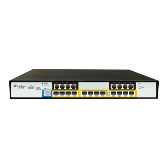
Page 54: Using The Home Page
MP-500 MSBG Using the Home Page The 'Home' page provides you with a graphical display of the device's front panel, displaying color-coded status icons for monitoring the functioning of the device. The 'Home' page also displays general device information (in the 'General Information' pane) such as the device's IP address and firmware version. - Page 55 SIP User's Manual 3. Web-Based Management Item # Description Module status icon: (green): Module has been inserted or is correctly configured. (gray): Module was removed. 'Reserved' is displayed alongside the module's name. (red): Module failure. 'Failure' is displayed instead of the module's name. Port/channel status icon.
-
Page 56: Assigning A Port Name
MP-500 MSBG 3.3.1 Assigning a Port Name The 'Home' page allows you to assign an arbitrary name or a brief description to each port. This description appears as a tooltip when you move your mouse over the port. To add a port description: Click the required port icon;... -
Page 57: Viewing Analog Port Information
SIP User's Manual 3. Web-Based Management 3.3.3 Viewing Analog Port Information The 'Home' page allows you to view detailed information on a specific FXS or FXO analog port such as RTP/RTCP and voice settings. To view detailed port information: Click the port for which you want to view port settings; the shortcut menu appears. Figure 3-32: Shortcut Menu From the shortcut menu, click Port Settings;... -
Page 58: Configuration Tab
MP-500 MSBG Configuration Tab The Configuration tab on the Navigation bar displays menus in the Navigation tree related to device configuration. These menus include the following: Network Settings (refer to ''Network Settings'' on page 58) Media Settings (refer to ''Media Settings'' on page 65) Security Settings (refer to ''Security Settings'' on page 132) Protocol Configuration (refer to ''Protocol Configuration'' on page 141) Advanced Applications (refer to ''Advanced Applications'' on page 224) -
Page 59: Figure 3-34: Multiple Interface Table Page
SIP User's Manual 3. Web-Based Management This page also provides VLAN-related parameters for enabling VLANs and for defining the 'Native' VLAN ID (VLAN ID to which incoming, untagged packets are assigned). For assigning VLAN priorities and Differentiated Services (DiffServ) for the supported Class of Service (CoS), refer to Configuring the QoS Settings on page 64. -
Page 60: Table 3-6: Multiple Interface Table Parameters Description
MP-500 MSBG Table 3-6: Multiple Interface Table Parameters Description Parameter Description Table parameters Index Index of each interface. The range is 0 to 15. Note: Each interface index must be unique. Web: Application Type Types of applications that are allowed on the specific EMS: Application Types interface. - Page 61 SIP User's Manual 3. Web-Based Management Parameter Description prefix length of 8 (i.e., 11111111 00000000 00000000 00000000), and a subnet mask of 255.255.255.252 is represented by a prefix length of 30 (i.e., 11111111 11111111 11111111 11111100). The prefix length is a Classless Inter-Domain Routing (CIDR) style presentation of a dotted-decimal subnet notation.
-
Page 62: Configuring The Application Settings
MP-500 MSBG Parameter Description General Parameters VLAN Mode For a description of this parameter, refer to “Networking [VlANMode] Parameters” on page 291. Native VLAN ID For a description of this parameter, refer to “Networking [VLANNativeVlanID] Parameters” on page 291. 3.4.1.2 Configuring the Application Settings The 'Application Settings' page is used for configuring various application parameters such as Network Time Protocol (NTP), daylight saving time, and Telnet. -
Page 63: Configuring The Ip Routing Table
SIP User's Manual 3. Web-Based Management 3.4.1.3 Configuring the IP Routing Table The 'IP Routing Table' page allows you to define up to 50 static IP routing rules for the device. For example, you can define static routing rules for the OAMP and Control networks since a default gateway is supported only for the Media traffic network. -
Page 64: Configuring The Qos Settings
MP-500 MSBG Parameter Description The address of the host / network you want to reach is determined by an AND operation that is applied to the fields 'Destination IP Address' and 'Destination Mask'. For example, to reach the network 10.8.x.x, enter 10.8.0.0 in the field 'Destination IP Address' and 255.255.0.0 in the field 'Destination Mask'. -
Page 65: Media Settings
SIP User's Manual 3. Web-Based Management To configure QoS: Open the 'QoS Settings' page (Configuration tab > Network Settings menu > QoS Settings page item). Figure 3-37: QoS Settings Page Configure the QoS parameters as required. Click the Submit button to save your changes. To save the changes to flash memory, refer to ''Saving Configuration'' on page 237. -
Page 66: Configuring The Voice Settings
MP-500 MSBG 3.4.2.1 Configuring the Voice Settings The 'Voice Settings' page is used for configuring various voice parameters such as voice volume, silence suppression, and DTMF transport type. For a detailed description of the parameters appearing on this page, refer to ''Configuration Parameters Reference'' on page 291. -
Page 67: Configuring The Fax/Modem/Cid Settings
SIP User's Manual 3. Web-Based Management 3.4.2.2 Configuring the Fax/Modem/CID Settings The 'Fax/Modem/CID Settings' page is used for configuring fax, modem, and Caller ID (CID) parameters. For a detailed description of the parameters appearing on this page, refer to ''Configuration Parameters Reference'' on page 291. To configure the fax, modem, and CID parameters: Open the 'Fax/Modem/CID Settings' page (Configuration tab >... -
Page 68: Configuring The General Media Settings
MP-500 MSBG To configure the RTP/RTCP parameters: Open the 'RTP/RTCP Settings' page (Configuration tab > Media Settings menu > RTP / RTCP Settings page item). Figure 3-40: RTP/RTCP Settings Page Configure the parameters as required. Click the Submit button to save your changes. To save the changes to flash memory, refer to ''Saving Configuration'' on page 237. -
Page 69: Configuring The Hook-Flash Settings
SIP User's Manual 3. Web-Based Management 3.4.2.5 Configuring the Hook-Flash Settings The 'Hook-Flash Settings' page allows you to configure hook-flash parameters. For a detailed description of the parameters appearing on this page, refer to ''Configuration Parameters Reference'' on page 291. To configure the Hook-Flash parameters: Open the 'Hook-Flash Settings' page (Configuration tab >... -
Page 70: Data Settings
MP-500 MSBG 3.4.3 Data Settings The Data Settings menu allows you to configure the device's data functionality. This menu contains the following submenus: WAN Access (refer to ''WAN Access Settings'' on page 72) Firewall (refer to ''Firewall Settings'' on page 74) QoS (refer to ''QoS Settings'' on page 87) VPN (refer to ''VPN Settings'' on page 97) Services (refer to ''Services Settings'' on page 106) -
Page 71: Figure 3-45: Disabling Table Entries
SIP User's Manual 3. Web-Based Management Icon Name Description Copy Copies an item to the clipboard. Move Up Moves an entry one place up in the table. Move Down Moves an entry one place down in the table. Once you have added an entry in a table, you can later disable the entry by clearing the check box corresponding to the entry. -
Page 72: Wan Access Settings
MP-500 MSBG 3.4.3.2 WAN Access Settings The WAN Access menu allows you to configure your WAN (Internet) connection. When subscribing to a broadband service, your Internet Service Provider (ISP) should provide you information regarding the method by which you are connecting to the Internet. The device can connect to the broadband service (WAN), using the following method: Ethernet interface (copper or fiber cable), using connection methods such as automatic IP address allocation or Point-to-Point Protocol over Ethernet (PPPoE). -
Page 73: Figure 3-47: Pppoe Wan Connection
SIP User's Manual 3. Web-Based Management ♦ Default gateway ♦ Primary DNS Server ♦ Secondary DNS Server • 'Point-to-Point Protocol over Ethernet (PPPoE)': specify the following information: ♦ Login user name ♦ Login password Figure 3-47: PPPoE WAN Connection • 'Point-to-Point Tunneling Protocol (PPTP)': specify the following information: ♦... -
Page 74: Firewall Settings
MP-500 MSBG ♦ Internet Protocol - select the method used by your ISP for assigning an IP address Figure 3-49: L2TP WAN Connection Type For advanced WAN settings, click the Click here for Advanced Settings link. For a detailed description of configuring advanced settings, refer to ''Configuring Network Connections'' on page 124. -
Page 75: Configuring General Security Settings
SIP User's Manual 3. Web-Based Management The Firewall menu includes the following items: General: allows you to choose the security level for the firewall (refer to ''Configuring General Security Settings'' on page 75). Access Control: allows you to restrict access from the device's network to the Internet (refer to ''Configuring Access Control'' on page 76). -
Page 76: Figure 3-51: Configuring General Security
MP-500 MSBG To configure basic security: Click the General item (Configuration tab > Data Settings menu > Firewall submenu > General page item); the following page appears: Figure 3-51: Configuring General Security Select one of the pre-defined security levels. Note: Selecting the 'Minimum Security' option may expose the enterprise's network to significant security risks, and therefore, should only be used if necessary. -
Page 77: Figure 3-52: Configuring Access Control
SIP User's Manual 3. Web-Based Management Note: When Web Filtering is enabled, HTTP services cannot be blocked by Access Control. To configure access control: Click the Access Control item (Configuration tab > Data Settings menu > Firewall submenu > Access Control page item); the following page appears: Figure 3-52: Configuring Access Control Click the New Entry link;... - Page 78 MP-500 MSBG You can disable an access control rule to make a service available without having to delete the rule. This may be useful if you wish to make the service temporarily available and expect to reinstate the restriction in the future. To disable an access rule: In the main Access Control page, clear the check box corresponding to the access rule that you want to disable.
-
Page 79: Figure 3-54: Configuring Port Forwarding
SIP User's Manual 3. Web-Based Management To configure a port forwarding service: Click the Port Forwarding item (Configuration tab > Data Settings menu > Firewall submenu > Port Forwarding page item); the following page appears: Figure 3-54: Configuring Port Forwarding Click the New Entry link;... -
Page 80: Figure 3-56: Defining A Dmz Host
MP-500 MSBG 3.4.3.3.4 Configuring a DMZ Host The DMZ (Demilitarized) Host feature allows a single local computer to be exposed to the Internet. You can designate a DMZ host for the following scenario examples: You wish to use a special-purpose Internet service, such as an on-line game or video conferencing program that is not present in the Port Forwarding list and for which no port range information is available. -
Page 81: Figure 3-57: Configuring Port Triggering
SIP User's Manual 3. Web-Based Management To configure port triggering: Click the Port Triggering item (Configuration tab > Data Settings menu > Firewall submenu > Port Triggering page item); the following page appears: Figure 3-57: Configuring Port Triggering From the drop-down list, you can select a pre-configured service by selecting 'Show All Services', and then from the refreshed drop-down list, selecting a service. -
Page 82: Figure 3-60: Configuring Website Restrictions
MP-500 MSBG 3.4.3.3.6 Configuring Website Restrictions You can configure the device to block specific Internet web sites so that they cannot be accessed from computers in the home network. Moreover, restrictions can be applied to a comprehensive and automatically-updated table of sites to which access is not recommended. -
Page 83: Figure 3-62: Configuring Nat
SIP User's Manual 3. Web-Based Management 3.4.3.3.7 Configuring NAT The device features a configurable Network Address Translation (NAT) and Network Address Port Translation (NAPT) mechanism, allowing you to control the network addresses and ports of packets routed through the device. When enabling multiple computers on your network to access the Internet using a fixed number of public IP addresses, you can define static NAT/NATP rules which map (translate) LAN IP addresses (LAN computers) to NAT IP addresses and/or ports. -
Page 84: Figure 3-64: Defining Nat/Napt Rule
MP-500 MSBG Define a new NAT/NAPT rule: Under the 'NAT/NAPT Rule Sets' group, click the New Entry link; the following page appears: Figure 3-64: Defining NAT/NAPT Rule This page is divided into two main groups: 'Matching' and 'Operation'. The 'Matching' group defines the LAN addresses to be translated to the external addresses, which are defined in the 'Operation' group. -
Page 85: Figure 3-65: Configuring Advanced Filtering
SIP User's Manual 3. Web-Based Management • NAPT: The NAPT address into which the original IP address is translated. The drop-down list displays all of your available NAPT addresses/ranges, from which you can select an entry. If you want to add a single address or a sub-range from the given pool/range, select 'User Defined' to add a new Network Object representing the new host (refer to ''Configuring Network Objects'' on page 121). -
Page 86: Figure 3-66: Adding An Advanced Filter
MP-500 MSBG The order of the rules' appearance represents both the order in which they are defined and the sequence by which they are applied. You may change this order, by using the icons. Select a device ('Rule ID') from one of the traffic direction sets ('Input Rule Sets' or 'Output Rule Sets'), by clicking its corresponding New Entry link;... - Page 87 SIP User's Manual 3. Web-Based Management Device: Select this check box to display a drop-down list, in which you can select a network device on which the packet-rule matching is performed. This option is relevant in case you have previously selected the 'All Devices' option in the 'Traffic Priority' page.
-
Page 88: Qos Settings
MP-500 MSBG 3.4.3.4 QoS Settings The device's Quality of Service (QoS) provides the capability to provide better service to selected network traffic. This is achieved by shaping the traffic and processing higher priority traffic before lower priority traffic. The QoS menu provides the following items: General (refer to ''Configuring General QoS Settings'' on page 88) Traffic Priority (refer to ''Configuring Traffic Priority'' on page 88) Traffic Shaping (refer to ''Configuring Traffic Shaping'' on page 91) -
Page 89: Figure 3-68: Configuring Traffic Priority
SIP User's Manual 3. Web-Based Management Source/destination ports Limit the rule for specific days and hours The device supports two priority marking methods for packet prioritization: DSCP (refer to ''Configuring DSCP Settings'' on page 95). 802.1p Priority (refer to ''Configuring 802.1p Settings'' on page 97). The matching of packets by rules is connection-based, known as Stateful Packet Inspection (SPI), using the same connection-tracking mechanism used by the device's firewall. -
Page 90: Figure 3-69: Adding A Traffic Priority Rule
MP-500 MSBG Click the New Entry link corresponding to the traffic direction (i.e., 'QoS Input Rules' or 'QoS Output Rules') and the device on which to set the rule; the following page appears: Figure 3-69: Adding a Traffic Priority Rule Under the 'Matching' group, define characteristics of the packets matching the QoS rule: •... - Page 91 SIP User's Manual 3. Web-Based Management • Device: Select this check box to display a drop-down list from which you can select a network device on which the packet-rule matching is performed. This option is relevant if you have previously selected the 'All Devices' option in the 'Traffic Priority'.
-
Page 92: Figure 3-70: Configuirng Traffic Shaping
MP-500 MSBG Prioritization policy TCP serialization on a device In addition, you can define QoS traffic shaping rules for a default device. These rules are used on a device that has no definitions of its own. This enables the definition of QoS rules on Default WAN, for example, and their maintenance even if the PPP or bridge device over the WAN is removed. -
Page 93: Figure 3-72: Defining Device Traffic Shaping
SIP User's Manual 3. Web-Based Management Click OK; the following page appears. Figure 3-72: Defining Device Traffic Shaping Under the 'Tx Traffic Shaping' group, configure the following: Tx Bandwidth: define the device's bandwidth transmission rate limit. TCP Serialization: You can enable TCP Serialization for active voice calls only or for all traffic. -
Page 94: Figure 3-74: Defining Shaping Class
MP-500 MSBG Click the newly added class name; the following page appears: Figure 3-74: Defining Shaping Class Configure the following fields: Name: name of the class. Class Priority: priority level of the class, where zero is the highest and seven the lowest. Bandwidth: reserved transmission bandwidth in kilobits per second. -
Page 95: Figure 3-75: Adding Rx Shaping Class
SIP User's Manual 3. Web-Based Management Queue Policy: Similar to Tx traffic, Rx traffic queueing can be based on a shaping class or on strict priority (unless unlimited bandwidth is selected). By default, however, the queue policy is set to Policer, which is a relatively simple method of bandwidth control. -
Page 96: Figure 3-77: Configuring Dscp Settings
MP-500 MSBG The device provides a table of predefined DSCP values, which are mapped to 802.1p priority marking method. You can edit or delete any of the existing DSCP settings, as well as add new entries. Each DSCP value is assigned a default queue number as a part of its 802.1p priority settings. -
Page 97: Figure 3-79: Configuring 802.1P Settings
SIP User's Manual 3. Web-Based Management 3.4.3.4.5 Configuring 802.1p Settings The IEEE 802.1p priority marking method is a standard for prioritizing network traffic at the data link/Mac sub-layer. 802.1p traffic is simply classified and sent to the destination, with no bandwidth reservations established. The 802.1p header includes a 3-bit prioritization field, which allows packets to be grouped into eight levels of priority (0-7), where level 7 is the highest. -
Page 98: Vpn Settings
MP-500 MSBG 3.4.3.5 VPN Settings The VPN menu allows you to configure Virtual Private Networking (VPN) over the Internet, and includes the following items: IPSec (refer to ''Configuring IPsec'' on page 98) PPTP (refer to ''Configuring PPTP Server'' on page 100) L2TP (refer to ''Configuring L2TP Server'' on page 102) 3.4.3.5.1 Configuring IPSec Internet Protocol Security (IPSec) is a series of guidelines for the protection of Internet... -
Page 99: Figure 3-81: Recreating Ipsec Public Key
SIP User's Manual 3. Web-Based Management To block unauthorized IP to the device, perform the following: Select the 'Block Unauthorized IP' check box. In the 'Maximum Number of Authentication Failures' field, enter the maximum number of packets to authenticate before blocking the origin's IP address. In the 'Block Period' field, enter the time frame during which the device drops packets from an unauthorized IP address. -
Page 100: Figure 3-82: Ipsec Log Settings
MP-500 MSBG Configure the IPSec log display for identifying and analyzing the history of the IPSec package commands, attempts to create connections, etc: Click the Log Settings button; the following page appears. Figure 3-82: IPSec Log Settings Select the check boxes relevant to the information you want the IPSec log to record. -
Page 101: Figure 3-83: Configuring Vpn Pptp Server
SIP User's Manual 3. Web-Based Management 3.4.3.5.2 Configuring PPTP Server The device can act as a Point-to-Point Tunneling Protocol Server (PPTP Server), accepting PPTP client connection requests. To configure PPTP: Click the PPTP item (Configuration tab > Data Settings menu > VPN submenu > PPTP page item);... -
Page 102: Figure 3-84: Configuring Vpn L2Tp Server
MP-500 MSBG 3.4.3.5.3 Configuring L2TP Server The device can act as a Layer 2 Tunneling Protocol Server (L2TP Server), accepting L2TP client connection requests. To configure L2PT: Click the L2TP item (Configuration tab > Data Settings menu > VPN submenu > L2TP page item);... -
Page 103: Figure 3-85: Adding Users
SIP User's Manual 3. Web-Based Management ♦ Select the 'Encryption Required' check box to enable L2TP to use encryption and then select the algorithms the server may use when encrypting data. ♦ From the 'MPPE Encryption Mode' drop-down list, select the Microsoft Point- to-Point Encryption mode: Stateless or Stateful. -
Page 104: Figure 3-86: Adding A New User
MP-500 MSBG To add a new user, under the 'Users' group, click the New User link; the following page appears: Figure 3-86: Adding a New User Under the General group, configure the following parameters: Full Name: remote user's full name. User Name: name that a user uses to access your network. -
Page 105: Figure 3-87: Defining Outgoing Mail Server
SIP User's Manual 3. Web-Based Management Configure an outgoing mail server: Figure 3-87: Defining Outgoing Mail Server Server: enter the hostname of your outgoing (SMTP) server. From Email Address: each email requires a 'from' address and some outgoing servers refuse to forward mail without a valid 'from' address for anti-spam considerations. -
Page 106: Services Settings
MP-500 MSBG To add a user group: Under the 'Groups' section, click the New Group link; the following page appears: Figure 3-88: Adding a User Group In the 'Name' field, enter a name for the group. In the 'Description' field, enter a short description for the group (optional). Under the Group Members section, select the users that you want to assign to this group. -
Page 107: Figure 3-89: Configuring Dynamic Dns (Ddns) Services
SIP User's Manual 3. Web-Based Management To create a dynamic DNS: Click the DDNS item (Configuration tab > Data Settings menu > Services submenu > DDNS page item); the following page appears: Figure 3-89: Configuring Dynamic DNS (DDNS) Services Click the New Dynamic DNS Entry link to add a new DDNS entry; the following page appears: Figure 3-90: Adding a DDNS In the 'Host Name' field, enter your full DDNS domain name. -
Page 108: Figure 3-91: Configuring A Dns Server
MP-500 MSBG • Offline: if you wish to temporarily take your site offline (prevent traffic from reaching your DDNS domain name), check this box to enable redirection of DNS requests to an alternative URL, predefined in your DDNS account. The availability of this feature depends on your account's level and type of service. -
Page 109: Figure 3-92: Adding A Dns Server
SIP User's Manual 3. Web-Based Management Click the New DNS Entry link; the following page appears: Figure 3-92: Adding a DNS Server In the 'Home Name' field, enter the computer's host name. In the 'IP Address' field, enter the computer's IP address. Click OK to save the settings. -
Page 110: Figure 3-93: Configuring Dhcp Server
MP-500 MSBG The device can also act as a DHCP relay, escalating DHCP responsibilities to a WAN DHCP server. In this case, the device acts merely as a router, while its LAN hosts receive their IP addresses from a DHCP server on the WAN. With the device's optional Zero Configuration Technology feature, the IP Auto Detection method detects statically-defined IP addresses in addition to the device's DHCP clients. -
Page 111: Figure 3-96: Defining Dhcp Relay (Dhcp For Lan Bridge)
SIP User's Manual 3. Web-Based Management Start IP Address: first IP address that can be assigned to a LAN host. Since the device's default IP address is 192.168.1.1, this address must be 192.168.1.2 or greater. End IP Address: last IP address in the range that can be used to automatically assign IP addresses to LAN hosts. -
Page 112: Figure 3-98: Computers Recognized By Dhcp Server
MP-500 MSBG You can also view a list of computers currently recognized by the DHCP server: To view a list of computers currently recognized by the DHCP server and to add a new PC with a static IP address: Click the DHCP Server item (Configuration tab > Data Settings menu > Services submenu >... -
Page 113: Routing Settings
SIP User's Manual 3. Web-Based Management 3.4.3.7 Routing Settings The Routing submenu allows you to configure the device's routing rules, and includes the following items: General (refer to ''Configuring General Routing Settings'' on page 113) BGP and OSPF (refer to ''Configuring BGP and OSPF'' on page 117) 3.4.3.7.1 Configuring General Routing Settings You can choose to setup your device to use static or dynamic routing. -
Page 114: Figure 3-100: Configuring General Routing
MP-500 MSBG Action – when a DNS test fails, the failover process simply removes the route records of the failed connection. This enables you to reach the desired failover behavior by configuring the device's routing rules correctly. Recover – during failover, tests continue to run on the failed connection. When a test succeeds, the connection recovers its route records. -
Page 115: Figure 3-102: Editing The Default Route
SIP User's Manual 3. Web-Based Management Define the following fields: ♦ Name: select the network device. ♦ Destination: enter the destination host, subnet address, network address, or default route. The destination for a default route is 0.0.0.0. ♦ Netmask: network mask is used in conjunction with the destination to determine when a route is used. -
Page 116: Figure 3-104: Adding Dscp-Based Route
MP-500 MSBG Click OK to save the settings. To add a DSCP-based policy route: Under the 'DSCP-Based Policy Routing' group, click the New Route link; the following page appears: Figure 3-104: Adding DSCP-Based Route From the 'Device' drop-down list, select the network device. In the 'DSCP' field, specify the DSCP value. - Page 117 SIP User's Manual 3. Web-Based Management To enable Internet Group Management Protocol (IGMP) multicasting: Under the 'Internet Group Management Protocol (IGMP)' group, select the 'Enabled' check box. When a host sends a request to join a multicast group, the device listens and intercept the group's traffic, forwarding it to the subscribed host. The device keeps record of subscribed hosts.
-
Page 118: Figure 3-106: Configuring Bgp And Ospf
MP-500 MSBG To enable BGP and OSPF: Click the BGP and OSPF item (Configuration tab > Data Settings menu > Routing submenu > BGP and OSPF page item); the following page appears: Figure 3-106: Configuring BGP and OSPF Select the 'Enabled' check box of the supported protocol(s); the page provides an area for configuration file, as shown in the example below: Figure 3-107: Page Displaying Area for Configuration File Create a configuration file for the protocol daemon and also for Zebra. - Page 119 SIP User's Manual 3. Web-Based Management • OSPF: router ospf A command that activates the OSPF daemon. log syslog • Zebra: interface ppp200 Instructs the daemon to query and update routing information via a specific WAN device. log syslog Click OK to save the settings. Version 5.8 October 2009...
-
Page 120: Objects And Rules Settings
MP-500 MSBG 3.4.3.8 Objects and Rules Settings The Objects and Rules submenu allows you to configure objects and rules, which can be used in other configuration pages. This submenu includes the following items: Protocols (refer to ''Configuring Protocols'' on page 120) Network Objects (refer to ''Configuring Network Objects'' on page 121) Scheduler Rules (refer to ''Configuring Scheduler Rules'' on page 122) 3.4.3.8.1 Configuring Protocols... -
Page 121: Figure 3-110: Defining Service Server Ports
SIP User's Manual 3. Web-Based Management In the 'Service Name' field, enter a name for the service. Click the New Server Ports link; the following page appears: Figure 3-110: Defining Service Server Ports From the 'Protocol' drop-down list, select any of the protocols available, or add a new one by selecting 'Other'. -
Page 122: Figure 3-113: Defining Network Object Type
MP-500 MSBG Click the New Entry link; the following page appears: Figure 3-113: Defining Network Object Type From the 'Network Object Type' drop-down list, select a network object type; the page displays the respective fields for entering the relevant information. The group definition can be according to one of the following: •... -
Page 123: Figure 3-116: Defining Time Segment
SIP User's Manual 3. Web-Based Management In the 'Name' field, specify a name for the rule. Under the 'Rule Activity Settings' group, specify whether the rule is active or inactive during the designated time period, by selecting the appropriate option. Click the New Time Segment Entry link to define the rule's time segment;... -
Page 124: Configuring Network Connections
MP-500 MSBG 3.4.3.9 Configuring Network Connections The device supports various network connections, both physical and logical. The Connections item enables you to configure the various parameters of your physical connections, the LAN and WAN, and create new connections, using tunneling protocols over existing connections, such as PPP and VPN. -
Page 125: Figure 3-119: Vpn Connection Types
SIP User's Manual 3. Web-Based Management Point-to-Point Tunneling Protocol (PPTP): a protocol developed by Microsoft targeted at creating VPN connections over the Internet. This enables remote users to access the device via any ISP that supports PPTP on its servers. PPTP encapsulates network traffic, encrypts content using Microsoft's Point-to-Point Encryption (MPPE) protocol that is based on RC4, and routes using the generic routing encapsulation (GRE) protocol. -
Page 126: Figure 3-120: Configuring Network Connections
MP-500 MSBG To add a network connection: Click the Connections item (Configuration tab > Data Settings menu > System submenu > Connections page item); the following page appears: Figure 3-120: Configuring Network Connections The page displays the following interfaces: • LAN Hardware Ethernet Switch: represents all the device's ports. -
Page 127: Figure 3-123: Defining Virtual Private Network Over Internet
SIP User's Manual 3. Web-Based Management • For configuring a VPN-over-Internet connection, perform the following: Select the 'Connect to a Virtual Private Network over the Internet' option, and then click Next; the following wizard page appears: Figure 3-123: Defining Virtual Private Network over Internet Select the VPN connection type, click Next, and then follow the instructions provided by the wizard. -
Page 128: Figure 3-124: Editing Network Connection - General Tab
MP-500 MSBG When the wizard completes the initial configuration (by clicking Finish), the new connection type appears listed in the main page. To perform advanced configuration, click the Edit action icon corresponding to the desired network connection; the following page providing tabs pertaining to the connection type appears (for example, for the LAN Hardware Ethernet Switch): Figure 3-124: Editing Network Connection - General Tab The default view is of the General tab, displaying a detailed summary of the... - Page 129 SIP User's Manual 3. Web-Based Management • Schedule: by default, the connection is always active. However, if you have defined scheduler rules (refer to ''Configuring Scheduler Rules'' on page 122), you can select one of these (time segments during which the connection is active). •...
-
Page 130: Figure 3-126: Editing Network Connection - Routing Tab
MP-500 MSBG Lease Time In Minutes: each host is assigned an IP address by the DHCP server for this amount of time when it connects to the network. When the lease expires the server determines if the computer has disconnected from the network. If it has, the server may reassign this IP address to a newly-connected computer. -
Page 131: Figure 3-127: Editing Network Connection - Switch Tab
SIP User's Manual 3. Web-Based Management • Multicast – IGMP Proxy Internal: the device serves as an IGMP proxy, issuing IGMP host messages on behalf of its LAN hosts. This check box is enabled on LAN connections by default, meaning that if a LAN multicast server is available, other LAN hosts asking to join multicast groups (by sending IGMP requests) are able to join its multicast group. -
Page 132: Figure 3-129: Editing Network Connection - Advanced Tab
MP-500 MSBG • Ingress Policy: Select whether or not to tag incoming packets with the port's VLAN header. When the 'Tagged (Add VLAN Header)' option is selected, additional fields appear. • Default VLAN ID: The port's VLAN identifier. You may add additional identifiers to the VLAN by clicking New Entry. -
Page 133: Security Settings
SIP User's Manual 3. Web-Based Management 3.4.4 Security Settings The Security Settings menu allows you to configure various security settings. This menu contains the following page items: Web User Accounts (refer to ''Configuring the Web User Accounts'' on page 133) WEB &... -
Page 134: Table 3-11: Default Attributes For The Web User Accounts
MP-500 MSBG The default attributes for the two Web user accounts are shown in the following table: Table 3-11: Default Attributes for the Web User Accounts Account / Attribute User Name Password Access Level (Case-Sensitive) (Case-Sensitive) Primary Account Admin Admin Security Administrator Note: The Access Level cannot be changed for this account... -
Page 135: Configuring The Web And Telnet Access List
SIP User's Manual 3. Web-Based Management To change the user name of an account, perform the following: In the field 'User Name', enter the new user name (maximum of 19 case-sensitive characters). Click Change User Name; if you are currently logged into the Web interface with this account, the 'Enter Network Password' dialog box appears, requesting you to enter the new user name. -
Page 136: Figure 3-131: Web & Telnet Access List Page - Add New Entry
MP-500 MSBG To add authorized IP addresses for Web and Telnet interfaces access: Open the 'Web & Telnet Access List' page (Configuration tab > Security Settings menu > Web & Telnet Access List page item). Figure 3-131: Web & Telnet Access List Page - Add New Entry To add an authorized IP address, in the 'Add a New Authorized IP Address' field, enter the required IP address, and then click Add New Address;... -
Page 137: Configuring The Certificates
SIP User's Manual 3. Web-Based Management 3.4.4.3 Configuring the Certificates The 'Certificates' page is used for both HTTPS and SIP TLS secure communication: Replacing the server certificate (refer to ''Server Certificate Replacement'' on page 137) Replacing the client certificates (refer to ''Client Certificates'' on page 139) Regenerating Self-Signed Certificates (refer to ''Self-Signed Certificates'' on page 140) Updating the private key (using HTTPSPkeyFileName, as described in the Product Reference Manual). - Page 138 MP-500 MSBG In the 'Subject Name' field, enter the DNS name, and then click Generate CSR. A textual certificate signing request that contains the SSL device identifier is displayed. Copy this text and send it to your security provider. The security provider (also known as Certification Authority or CA) signs this request and then sends you a server certificate for the device.
-
Page 139: Figure 3-134: Ike Table Listing Loaded Certificate Files
SIP User's Manual 3. Web-Based Management To apply the loaded certificate for IPsec negotiations: Open the ‘IKE Table’ page (refer to Configuring the IKE Table); the 'Loaded Certificates Files' group lists the newly uploaded certificates, as shown below: Figure 3-134: IKE Table Listing Loaded Certificate Files Click the Apply button to load the certificates;... - Page 140 MP-500 MSBG When operation complete, file parameter HTTPSRequireClientCertificates to 1. Save the configuration (refer to ''Saving Configuration'' on page 237), and then restart the device. When a user connects to the secured Web server: If the user has a client certificate from a CA that is listed in the Trusted Root Certificate file, the connection is accepted and the user is prompted for the system password.
-
Page 141: Configuring The General Security Settings
SIP User's Manual 3. Web-Based Management 3.4.4.4 Configuring the General Security Settings The 'General Security Settings' page is used to configure various security features. For a description of the parameters appearing on this page, refer ''Configuration Parameters Reference'' on page 291. To configure the general security parameters: Open the 'General Security Settings' page (Configuration tab >... -
Page 142: Protocol Configuration
MP-500 MSBG 3.4.5 Protocol Configuration The Protocol Configuration menu allows you to configure the device's SIP parameters and contains the following submenus: Applications Enabling (refer to “Enabling Applications” on page 142) Protocol Definition (refer to ''Protocol Definition'' on page 144) Proxies/IpGroups/Registration (refer to ''Proxies, IP Groups, and Registration'' on page 146) Coders And Profile Definitions (refer to ''Coders and Profile Definitions'' on page 160) -
Page 143: Configuring Media Realms
SIP User's Manual 3. Web-Based Management 3.4.5.2 Configuring Media Realms The 'SIP Media Realm Table' page allows you to define a pool of up to 16 media interfaces, termed Media Realms. This table allows you to divide a Media-type interface (defined in the 'Multiple Interface' table - refer to ''Configuring the Multiple Interface Table'' on page 58) into several realms, where each realm is specified by a UDP port range. -
Page 144: Protocol Definition
MP-500 MSBG Parameter Description This Media Realm name is used in the 'SRD' and/or 'IP Groups' table. IPv4 Name Associates the IPv4 interface to the Media Realm. The name [CpMediaRealm_IPv4IF] of this IPv4 interface must be exactly as configured in the 'Multiple Interface' table (InterfaceTable). -
Page 145: Figure 3-138: Sip General Parameters
SIP User's Manual 3. Web-Based Management 3.4.5.3.1 Configuring SIP General Parameters The 'SIP General Parameters' page is used to configure general SIP parameters. For a description of the parameters appearing on this page, refer to ''Configuration Parameters Reference'' on page 291. To configure the general SIP protocol parameters: Open the 'SIP General Parameters' page (Configuration tab >... -
Page 146: Proxies, Ip Groups, And Registration
MP-500 MSBG Configure the parameters as required. Click the Submit button to save your changes. To save the changes to flash memory, refer to ''Saving Configuration'' on page 237. 3.4.5.3.2 Configuring DTMF and Dialing Parameters The 'DTMF & Dialing' page is used to configure parameters associated with dual-tone multi- frequency (DTMF) and dialing. -
Page 147: Figure 3-140: Proxy & Registration
SIP User's Manual 3. Web-Based Management 3.4.5.4.1 Configuring Proxy and Registration Parameters The 'Proxy & Registration' page allows you to configure parameters that are associated with Proxy and Registration. For a description of the parameters appearing on this page, refer to ''Configuration Parameters Reference'' on page 291. - Page 148 MP-500 MSBG Click the Submit button to save your changes, or click the Register or Un-Register buttons to save your changes and register / unregister to a Proxy / Registrar. To save the changes to flash memory, refer to ''Saving Configuration'' on page 237. Click the Proxy Set Table button to open the 'Proxy Sets Table' page to configure groups of proxy addresses.
-
Page 149: Table 3-13: Proxy Sets Table Parameters
SIP User's Manual 3. Web-Based Management To add Proxy servers and configure Proxy parameters: Open the 'Proxy Sets Table' page (Configuration tab > Protocol Configuration menu > Proxies/IpGroups/Registration submenu > Proxy Sets Table page item). Figure 3-141: Proxy Sets Table Page From the Proxy Set ID drop-down list, select an ID for the desired group. - Page 150 MP-500 MSBG Parameter Description configure the default Proxy Set if the parameter PreferRouteTable is setto 1. To summarize, if the default Proxy Set is used, the INVITE message is sent according to the following preferences: To the Hunt Group's Serving IP Group ID, as defined in the 'Hunt Group Settings' table.
- Page 151 SIP User's Manual 3. Web-Based Management Parameter Description Web: Proxy Load Balancing Enables the Proxy Load Balancing mechanism per Proxy Set ID. Method [0] Disable = Load Balancing is disabled (default). EMS: Load Balancing Method [1] Round Robin = Round Robin. [ProxyLoadBalancingMethod] [2] Random Weights = Random Weights.
- Page 152 MP-500 MSBG Parameter Description redundancy mode is disabled. When the active proxy doesn't respond to INVITE messages sent by the device, the proxy is tagged as 'offline'. The behavior is similar to a Keep-Alive (OPTIONS or REGISTER) failure. Web: Proxy Keep Alive Time Defines the Proxy keep-alive time interval (in seconds) between EMS: Keep Alive Time Keep-Alive messages.
-
Page 153: Figure 3-142: Ip Group Table
SIP User's Manual 3. Web-Based Management Notes: • By default, if you disable the use of a proxy (i.e., IsProxyUsed is set to 0), then only one IP Group is defined (and working with multiple IP Groups is not valid). •... -
Page 154: Table 3-14: Ip Group Parameters
MP-500 MSBG Table 3-14: IP Group Parameters Parameter Description Common Parameters Type The IP Group can be defined as one of the following types: [IPGroup_Type] SERVER = used when the destination address (configured by the Proxy Set) of the IP Group (e.g., ITSP, Proxy, IP- PBX, or Application server) is known. - Page 155 SIP User's Manual 3. Web-Based Management Parameter Description Note: If the IP Group is of type USER, this parameter is used internally as a hostname in the request URI for PSTN-to-IP initiated calls. For example, if an incoming call from the device is routed to a USER-type IP Group, the device first forms the request URI (<destination_number>@<SIP Group Name>), and then it searches the user’s internal database for a match.
- Page 156 MP-500 MSBG Parameter Description page 147). [2] Request-URI = The device sends the SIP INVITE to the IP address according to the received SIP Request-URI host name. Note: This field is available only if the SBC application is enabled. SIP Re-Routing Mode Determines the routing mode after a call redirection (i.e., a 3xx [IPGroup_SIPReRoutingMode] SIP response is received) or transfer (i.e., a SIP REFER...
- Page 157 SIP User's Manual 3. Web-Based Management Parameter Description This parameter is applicable only to USER-type IP Groups. Serving IP Group ID If configured, INVITE messages initiated from the IP Group are [IPGroup_ServingIPGroup] sent to this Serving IP Group (range 1 to 9). In other words, the INVITEs are sent to the address defined for the Proxy Set associated with this Serving IP Group.
-
Page 158: Table 3-15: Account Table Parameters Description
MP-500 MSBG To configure Accounts: Open the 'Account Table' page (Configuration tab > Protocol Configuration menu > Proxies/IpGroups/Registration submenu > Account Table page item). Figure 3-143: Account Table Page To add an Account, in the 'Add' field, enter the desired table row index, and then click Add. - Page 159 'Hunt Group Settings' table for the specific Hunt Group. The Host Name (i.e., host name in SIP From/To headers) and Contact User (user in From/To and Contact headers) are taken from this table upon a successful registration. See the example below: REGISTER sip:audiocodes SIP/2.0 Via: SIP/2.0/UDP 10.33.37.78;branch=z9hG4bKac1397582418 From: <sip:ContactUser@HostName>;...
-
Page 160: Coders And Profile Definitions
MP-500 MSBG Parameter Description Contact User Defines the AOR user name. It appears in REGISTER From/To [Account_ContactUser] headers as ContactUser@HostName, and in INVITE/200 OK Contact headers as ContactUser@<device's IP address>. If not configured, the 'Contact User' parameter from the 'IP Group Table' page is used instead. -
Page 161: Configuring Coders
SIP User's Manual 3. Web-Based Management Each call can be associated with one or two Profiles - Tel Profile and/or IP Profile. If both IP and Tel profiles apply to the same call, the coders and other common parameters of the preferred Profile (determined by the Preference option) are applied to that call. -
Page 162: Figure 3-144: Coders
MP-500 MSBG To configure the device's coders: Open the 'Coders' page (Configuration tab > Protocol Configuration menu > Coders And Profile Definition submenu > Coders page item). Figure 3-144: Coders Page From the 'Coder Name' drop-down list, select the required coder. For the full list of available coders and their corresponding attributes, refer to the parameter CoderName (refer to ''SIP Configuration Parameters'' on page 318). -
Page 163: Configuring Coder Groups
SIP User's Manual 3. Web-Based Management 3.4.5.5.2 Configuring Coder Groups The 'Coder Group Settings' page provides a table for defining up to four different coder groups. These coder groups are used in the 'Tel Profile Settings' and 'IP Profile Settings' pages to assign different coders to Profiles. -
Page 164: Figure 3-145: Coder Group Settings
MP-500 MSBG To configure coder groups: Open the 'Coder Group Settings' page (Configuration tab > Protocol Configuration menu > Coders And Profile Definition submenu > Coder Group Settings page item). Figure 3-145: Coder Group Settings Page From the 'Coder Group ID' drop-down list, select a coder group ID. From the 'Coder Name' drop-down list, select the first coder for the coder group. -
Page 165: Figure 3-146: Tel Profile Settings
SIP User's Manual 3. Web-Based Management To configure Tel Profiles: Open the 'Tel Profile Settings' page (Configuration tab > Protocol Configuration menu > Coders And Profile Definition submenu > Tel Profile Settings page item). Figure 3-146: Tel Profile Settings Page From the 'Profile ID' drop-down list, select the Tel Profile identification number you want to configure. - Page 166 MP-500 MSBG From the 'Profile Preference' drop-down list, select the priority of the Tel Profile, where '1' is the lowest priority and '20' is the highest. If both IP and Tel profiles apply to the same call, the coders and other common parameters (noted by an asterisk in the description of the parameter TelProfile) of the preferred Profile are applied to that call.
-
Page 167: Figure 3-147: Ip Profile Settings
SIP User's Manual 3. Web-Based Management To configure the IP Profile settings: Open the 'IP Profile Settings' page (Configuration tab > Protocol Configuration menu > Coders And Profile Definition submenu > IP Profile Settings). Figure 3-147: IP Profile Settings Page From the 'Profile ID' drop-down list, select an identification number for the IP Profile. -
Page 168: Sip Advanced Parameters
MP-500 MSBG From the 'Profile Preference' drop-down list, select the priority of the IP Profile, where '1' is the lowest priority and '20' is the highest. If both IP and Tel profiles apply to the same call, the coders and other common parameters (noted by an asterisk) of the preferred Profile are applied to that call. -
Page 169: Figure 3-148: Advanced Parameters
SIP User's Manual 3. Web-Based Management 3.4.5.6.1 Configuring Advanced Parameters The 'Advanced Parameters' page allows you to configure advanced SIP control parameters. For a description of the parameters appearing on this page, refer to ''Configuration Parameters Reference'' on page 291. To configure the advanced general protocol parameters: Open the 'Advanced Parameters' page (Configuration tab >... -
Page 170: Figure 3-149: Supplementary Services
MP-500 MSBG Configure the parameters as required. Click the Submit button to save your changes. To save the changes to flash memory, refer to ''Saving Configuration'' on page 237. 3.4.5.6.2 Configuring Supplementary Services The 'Supplementary Services' page is used to configure parameters that are associated with supplementary services. -
Page 171: Figure 3-150: Metering Tones
SIP User's Manual 3. Web-Based Management Configure the parameters as required. Click the Submit button to save your changes, or click the Subscribe to MWI or Unsubscribe to MWI buttons to save your changes and to subscribe / unsubscribe to the MWI server. -
Page 172: Figure 3-151: Charge Codes Table
MP-500 MSBG 3.4.5.6.4 Configuring the Charge Codes Table The 'Charge Codes Table' page is used to configure the metering tones (and their time interval) that the FXS interfaces generate to the Tel side. To associate a charge code to an outgoing Tel-to-IP call, use the 'Tel to IP Routing' table. - Page 173 SIP User's Manual 3. Web-Based Management 3.4.5.6.5 Configuring Keypad Features The 'Keypad Features' page enables you to activate and deactivate the following features directly from the connected telephone's keypad: Call Forward (refer to ''Configuring Call Forward'' on page 216) Caller ID Restriction (refer to ''Configuring Caller Display Information'' on page 214) Hotline (refer to ''Configuring Automatic Dialing'' on page 213) Call transfer Call waiting (refer to ''Configuring Call Waiting'' on page 218)
-
Page 174: Figure 3-152: Keypad Features
MP-500 MSBG To configure the keypad features Open the 'Keypad Features' page (Configuration tab > Protocol Configuration menu > SIP Advanced Parameters submenu > Keypad Features page item). Figure 3-152: Keypad Features Page Configure the keypad features as required. For a description of these parameters, refer to ''Configuration Parameters Reference'' on page 291. -
Page 175: Sas Parameters
SIP User's Manual 3. Web-Based Management 3.4.5.7 SAS Parameters The SAS submenu allows you to configure the SAS application. This submenu includes the Stand Alone Survivability item page (refer to ''Configuring Stand-Alone Survivability Parameters'' on page 175), from which you can also access the 'IP2IP Routing Table' page for configuring SAS routing rules (refer to ''Configuring the IP2IP Routing Table (SAS)'' on page 176). -
Page 176: Figure 3-153: Sas Configuration
MP-500 MSBG To configure the Stand-Alone Survivability parameters: Open the 'SAS Configuration' page (Configuration tab > Protocol Configuration menu > SAS submenu > Stand Alone Survivability page item). Figure 3-153: SAS Configuration Page Configure the parameters as described in ''SIP Configuration Parameters'' on page 318. -
Page 177: Table 3-17: Sas Routing Table Parameters
SIP User's Manual 3. Web-Based Management 3.4.5.7.2 Configuring the IP2IP Routing Table (SAS) The 'IP2IP Routing Table' page configures SAS routing when SAS is in Emergency mode. Up to 120 SAS routing rules can be defined. The device routes the SAS call (received SIP INVITE message) once a rule in this table is matched. - Page 178 MP-500 MSBG Parameter Description Destination Username Prefix The prefix of the incoming SIP INVITE's destination URI [IP2IPRouting_DestUsernamePrefix] (usually the Request URI) user part. If this rule is not required, leave the field empty. To denote any prefix, use the asterisk (*) symbol. The default is "*".
- Page 179 SIP User's Manual 3. Web-Based Management Parameter Description define an IP Group but only an SRD, then the first IP Group associated with this SRD (in the 'IP Group' table) is used. Destination SRD ID Determines the SRD ID. [IP2IPRouting_DestSRDID] The default is -1.
-
Page 180: Configuring The Sbc Tables
MP-500 MSBG 3.4.5.8 Configuring the SBC Tables The SBC submenu provides configuration page for configuring the SBC application. This submenu includes the following items: General Settings (refer to ''Configuring General SBC Settings'' on page 180) SRD Table (refer to ''Configuring the Signaling Routing Domain Table'' on page 180) SIP Interface Table (refer to ''Configuring the SIP Interface Table'' on page 182) Classification Table (refer to ''Configuring the Classification Table'' on page 184) IP2IP Routing Table (refer to ''Configuring the SBC IP2IP Routing Table'' on page 186) -
Page 181: Figure 3-156: Srd Table
SIP User's Manual 3. Web-Based Management 3.4.5.8.2 Configuring the Signaling Routing Domain Table The 'SRD Table' page allows you to configure up to five signaling routing domains (SRD). An SRD is a set of definitions of IP interfaces, device resources, SIP behaviors and other definitions that together create (from the IP user’s perspective) from one physical device, multiple virtual multi-service gateways. -
Page 182: Table 3-18: Srd Table Parameters
MP-500 MSBG Click the Apply button to save your changes. To save the changes to flash memory, refer to ''Saving Configuration'' on page 237. Table 3-18: SRD Table Parameters Parameter Description Name Mandatory descriptive name of the SRD. [SRD_Name] The valid value can be a string of up to 21 characters. Media Realm Determines the media ports associated with the specific SRD. -
Page 183: Table 3-19: Sip Interface Table Parameters
SIP User's Manual 3. Web-Based Management To configure the SIP Interface table: Open the 'SIP Interface Table' page (Configuration tab > Protocol Configuration menu > SBC submenu > SIP Interface Table). Figure 3-157: SIP Interface Table Page Add an entry and then configure it according to the table below. Click the Apply button to save your changes. - Page 184 MP-500 MSBG Parameter Description TLS Port Determines the listening TLS port. [SIPInterface_TLSPort] The valid range is 1 to 65534. The default is 5061. Note: This port must be outside of the RTP port range. Determines the SRD ID (configured in the 'SRD' table) [SIPInterface_SRD] associated with the SIP Interface.
-
Page 185: Table 3-20: Classification Table Parameters
SIP User's Manual 3. Web-Based Management Notes: • For a specific classification rule to be effective, the incoming SIP dialog message must match the characteristics configured for that rule. • Incoming REGISTER messages are recorded in the device’s database and sent to a destination only if they are associated with a source IP Group that is of USER type. - Page 186 MP-500 MSBG Parameter Description Source Username Prefix The prefix of the user part of the incoming SIP dialog [Classification_SrcUsernamePrefix] request's source URI (usually the From URI). Source Host Prefix The From header URI host name prefix of the incoming SIP [Classification_SrcHost] dialog request.
-
Page 187: Table 3-21: Ip2Ip Routing Table Parameters
SIP User's Manual 3. Web-Based Management In addition to the alternative routing/load balancing provided by the Destination IP Group's associated Proxy Set, the 'IP2IP Routing' table allows the configuration of alternative routes whereby if a route fails, the next adjacent rule in the table that is configured as 'Alt Route Ignore/Consider Inputs' are used. - Page 188 MP-500 MSBG Parameter Description Destination Username Prefix The prefix of the incoming SIP INVITE's destination URI [IP2IPRouting_DestUsernamePrefix] (usually the Request URI) user part. If this rule is not required, leave the field empty. To denote any prefix, use the asterisk (*) symbol. The default is "*".
- Page 189 SIP User's Manual 3. Web-Based Management Parameter Description define an IP Group but only an SRD, then the first IP Group associated with this SRD (in the 'IP Group' table) is used. Destination SRD ID Determines the SRD ID. [IP2IPRouting_DestSRDID] The default is -1.
- Page 190 MP-500 MSBG Parameter Description Alternative Route Options Determines whether this routing rule is the main routing rule [IP2IPRouting_AltRouteOptions] or an alternative routing rule (to the rule defined directly above it in the table). [0] Route Row (default) = Main routing rule - the device first attempts to route the call to this route if the incoming INVITE's input characteristics matches this rule.
-
Page 191: Figure 3-160: Ip2Ip Inbound Manipulation
SIP User's Manual 3. Web-Based Management 3.4.5.8.6 Configuring the IP to IP Inbound Manipulation Table The 'IP to IP Inbound Manipulation Table' page allows you to configure up to 100 manipulation rules for SIP URI user part (source and destination) manipulations. Manipulation rules in the table are located according to the source IP Group, and source and destination host and user prefixes. -
Page 192: Table 3-22: Ip To Ip Inbound Manipulation Table Parameters
MP-500 MSBG Table 3-22: IP to IP Inbound Manipulation Table Parameters Parameter Description Matching Characteristics IsAdditionalManipulation Determines whether additional SIP URI user part manipulation is [IsAdditionalManipulation] performed for the table entry rule listed directly above it. [0] 0 = Regular manipulation rule (not performed in addition to the rule above it). -
Page 193: Table 3-23: Ip To Ip Outbound Manipulation Table Parameters
SIP User's Manual 3. Web-Based Management 3.4.5.8.7 Configuring the IP to IP Outbound Manipulation Table The 'IP to IP Outbound Manipulation Table' page allows you to configure up to 100 manipulation rules for SIP URI user part (source and destination) manipulations for outbound SIP dialog requests. - Page 194 MP-500 MSBG Parameter Description [1] 1 = If the previous table row entry rule matched the call, consider this row entry as a match as well and perform the manipulation specified by this rule. Note: Additional manipulation can only be performed on a different SIP URI (either source or destination) to the rule configured in the row above (defined by the parameter ManipulatedURI).
-
Page 195: Gateway Manipulation Tables
SIP User's Manual 3. Web-Based Management 3.4.5.9 Gateway Manipulation Tables The Manipulation Tables submenu allows you to configure number manipulation and mapping of NPI/TON to SIP messages. This submenu includes the following items: Dest Number IP->Tel (refer to ''Configuring the Number Manipulation Tables'' on page 195) Dest Number Tel->IP (refer to ''Configuring the Number Manipulation Tables'' on page 195) -
Page 196: Figure 3-162: Source Phone Number Manipulation Table For Tel-To-Ip Calls
MP-500 MSBG Notes: • Number manipulation can occur before or after a routing decision is made. For example, you can route a call to a specific Hunt Group according to its original number, and then you can remove or add a prefix to that number before it is routed. -
Page 197: Table 3-24: Number Manipulation Parameters Description
SIP User's Manual 3. Web-Based Management • Index 3: When the source number has prefix 123451001 (e.g., 1234510012001), it is changed to 20018. • Index 4: When the source number has prefix from 30 to 40 and a digit (e.g., 3122), it is changed to 2312. - Page 198 MP-500 MSBG Parameter Description single digits. For example: 10.8.8.xx represents all IP addresses between 10.8.8.10 to 10.8.8.99. The source IP address can include the asterisk (*) wildcard to represent any number between 0 and 255. For example, 10.8.8.* represents all IP addresses between 10.8.8.0 and 10.8.8.255. Web: Stripped Digits From Number of digits to remove from the left of the telephone number Left...
-
Page 199: Table 3-25: Phone-Context Parameters Description
SIP User's Manual 3. Web-Based Management For example, for a Tel-to-IP call with NPI/TON set as E164 National (values 1/2), the device sends the outgoing SIP INVITE URI with the following settings: “sip:12365432;phone- context= na.e.164.nt.com“. This is configured for entry 3 in the figure below. In the opposite direction (IP-to-Tel call), if the incoming INVITE contains this Phone-Context (e.g. -
Page 200: Routing Tables
MP-500 MSBG Parameter Description Select the Number Plan assigned to this entry. [0] Unknown = Unknown (default) [1] E.164 Public = E.164 Public [9] Private = Private Select the Type of Number assigned to this entry. If you selected Unknown as the NPI, you can select Unknown [0]. If you selected Private as the NPI, you can select one of the following: [0] Unknown... - Page 201 SIP User's Manual 3. Web-Based Management 3.4.5.10.1 Configuring General Routing Parameters The 'Routing General Parameters' page allows you to configure the general routing parameters. For a description of these parameters, refer to ''Configuration Parameters Reference'' on page 291. To configure the general routing parameters: Open the 'Routing General Parameters' page (Configuration tab >...
- Page 202 MP-500 MSBG Obtain different SIP URI host names (per called number). Assign IP profiles. Note that for this table to take precedence over a Proxy for routing calls, set the parameter PreferRouteTable to 1. The device checks the 'Destination IP Address' field in this table for a match with the outgoing call.
-
Page 203: Table 3-26: Tel To Ip Routing Table Parameters
SIP User's Manual 3. Web-Based Management Notes: • If the alternative routing destination is the device itself, the call can be configured to be routed back to the PSTN. This feature is referred to as 'PSTN Fallback', meaning that if poor voice quality occurs over the IP network, the call is routed through the legacy telephony system (PSTN). - Page 204 MP-500 MSBG Parameter Description Web: Src. Trunk Group ID The source Hunt Group ID of the call. EMS: Source Trunk Group ID The range is 1-99. [PREFIX_SrcTrunkGroupID] Notes: If this parameter is not required in the routing rule, leave the field empty.
- Page 205 SIP User's Manual 3. Web-Based Management Parameter Description represent single digits, e.g., 10.8.8.xx represents all addresses between 10.8.8.10 to 10.8.8.99. The '*' wildcard represents any number between 0 and 255, e.g., 10.8.8.* represents all addresses between 10.8.8.0 and 10.8.8.255. Web: Port The destination port to where you want to route the call.
- Page 206 MP-500 MSBG 3.4.5.10.3 Configuring the IP to Trunk Group Routing Table The 'IP to Hunt Group Routing Table' page provides a table for routing incoming IP calls to groups of channels (FXS/FXO endpoints) called Hunt Groups. Hunt Group ID's are assigned to the device's channels in the 'Trunk Group Table' page (refer to “Configuring the Trunk Group Table”...
-
Page 207: Table 3-27: Ip To Hunt Group Routing Table Description
SIP User's Manual 3. Web-Based Management From the 'Routing Index' drop-down list, select the range of entries that you want to add. Configure the table according to the table below. Click the Submit button to save your changes. To save the changes so they are available after a power failure, refer to ''Saving Configuration'' on page 237. -
Page 208: Figure 3-164: Internal Dns Table
MP-500 MSBG Parameter Description The source IP address can include the "x" wildcard to represent single digits. For example: 10.8.8.xx represents all the addresses between 10.8.8.10 to 10.8.8.99. The source IP address can include the asterisk (*) wildcard to represent any number between 0 and 255. For example, 10.8.8.* represents all addresses between 10.8.8.0 and 10.8.8.255. -
Page 209: Figure 3-165: Internal Srv Table
SIP User's Manual 3. Web-Based Management Optionally, in the 'Second IP Address', 'Third IP Address', and 'Second IP Address' fields, enter the next IP addresses to which the host name is translated. Click the Submit button to save your changes. To save the changes to flash memory, refer to ''Saving Configuration'' on page 237. - Page 210 MP-500 MSBG 3.4.5.10.6 Configuring Reasons for Alternative Routing The 'Reasons for Alternative Routing' page allows you to define up to four different call release (termination) reasons for IP-to-Tel call releases and for Tel-to-IP call releases. If a call is released as a result of one of these reasons, the device tries to find an alternative route for that call.
-
Page 211: Figure 3-166: Reasons For Alternative Routing
SIP User's Manual 3. Web-Based Management To configure the reasons for alternative routing: Open the 'Reasons for Alternative Routing' page (Configuration tab > Protocol Configuration menu > Routing Tables submenu > Reasons for Alternative Routing page item). Figure 3-166: Reasons for Alternative Routing Page In the 'IP to Tel Reasons' group, select up to four different call failure reasons that invoke an alternative IP-to-Tel routing. -
Page 212: Endpoint Settings
MP-500 MSBG 3.4.5.11 Endpoint Settings The Endpoint Settings submenu allows you to configure analog (FXS/FXO) port-specific parameters. This submenu includes the following page items: Authentication (refer to ''Configuring Authentication'' on page 212) Automatic Dialing (refer to ''Configuring Automatic Dialing'' on page 213) Caller Display Information (refer to ''Configuring Caller Display Information'' on page 214) Call Forward (refer to ''Configuring Call Forward'' on page 216) -
Page 213: Figure 3-167: Authentication
SIP User's Manual 3. Web-Based Management To configure the Authentication Table: Set the parameter 'Authentication Mode' to 'Per Endpoint' (refer to ''Configuring Proxy and Registration Parameters'' on page 147). Open the 'Authentication' page (Configuration tab > Protocol Configuration menu > Endpoint Settings submenu >... -
Page 214: Figure 3-168: Automatic Dialing
MP-500 MSBG To configure Automatic Dialing: Open the 'Automatic Dialing' page (Configuration tab > Protocol Configuration menu > Endpoint Settings submenu > Automatic Dialing page item). Figure 3-168: Automatic Dialing Page In the 'Destination Phone Number' field corresponding to a port, enter the telephone number that you want automatically dialed. -
Page 215: Figure 3-169: Caller Display Information
SIP User's Manual 3. Web-Based Management To configure the Caller Display Information: Open the 'Caller Display Information' page (Configuration tab > Protocol Configuration menu > Endpoint Settings submenu > Caller Display Information page item). Figure 3-169: Caller Display Information Page In the' Caller ID/Name' field corresponding to the desired port, enter the Caller ID string (up to 18 characters). -
Page 216: Table 3-28: Call Forward Table
MP-500 MSBG 3.4.5.11.4 Configuring Call Forward The 'Call Forwarding Table' page allows you to forward (redirect) IP-to-Tel calls (using SIP 302 response) originally destined to specific device ports, to other device ports or to an IP destination. Notes: • Ensure that the Call Forward feature is enabled (default) for the settings on this page to take effect. -
Page 217: Figure 3-171: Caller Id Permissions
SIP User's Manual 3. Web-Based Management Parameter Description 'Time for No Reply Forward' field. [5] Do Not Disturb = Immediately reject incoming calls. The telephone number or URI (<number>@<IP address>) to where the Forward to Phone Number call is forwarded. Note: If this field only contains a telephone number and a Proxy isn't used, the 'forward to' phone number must be specified in the 'Tel to IP Routing' table (refer to ''Configuring the Tel to IP Routing Table'' on page... - Page 218 MP-500 MSBG From the 'Caller ID' drop-down list, select one of the following: • 'Enable': Enables Caller ID generation (FXS) or detection (FXO) for the specific port. • 'Disable': Caller ID generation (FXS) or detection (FXO) for the specific port is disabled.
-
Page 219: Figure 3-172: Call Waiting
SIP User's Manual 3. Web-Based Management To configure Call Waiting: Open the 'Caller Waiting' page (Configuration tab > Protocol Configuration menu > Endpoint Settings submenu > Call Waiting page item). Figure 3-172: Call Waiting Page From the 'Call Waiting Configuration' drop-down list corresponding to the port you want to configure for call waiting, select one of the following options: •... -
Page 220: Hunt Groups
MP-500 MSBG 3.4.5.12 Hunt Groups The Hunt Group submenu allows you to configure groups of channels called Hunt Groups. This submenu includes the following page item: Hunt Group (refer to “Configuring the Trunk Group Table” on page 220) Hunt Group Settings (refer to ''Configuring the Trunk Group Settings'' on page 222) 3.4.5.12.1 Configuring the Hunt Group Table The 'Hunt Group Table' page allows you to enable the device's channels by assigning them telephone numbers and other attributes (e.g., Hunt Groups and Profiles). -
Page 221: Table 3-29: Trunk Group Table Parameters
SIP User's Manual 3. Web-Based Management Click the Submit button to save your changes. To save the changes to the flash memory, refer to ''Saving Configuration'' on page 237. Table 3-29: Trunk Group Table Parameters Parameter Description Module The module type (i.e., FXS/FXO) for which you want to define [TrunkGroup_Module] the Trunk Group. -
Page 222: Figure 3-174: Hunt Group Settings
Per Endpoint mode. The "SipGroupName" in the request URI is taken from the IP Group table. REGISTER sip:SipGroupName SIP/2.0 Via: SIP/2.0/UDP 10.33.37.78;branch=z9hG4bKac862428454 From: <sip:101@GatewayName>;tag=1c862422082 To: <sip:101@GatewayName> Call-ID: 9907977062512000232825@10.33.37.78 CSeq: 3 REGISTER Contact: <sip:101@10.33.37.78>;expires=3600 Expires: 3600 User-Agent: Audiocodes-Sip-Gateway/v.5.80A.008.002 Content-Length: 0 SIP User's Manual Document #: LTRT-12801... -
Page 223: Table 3-30: Hunt Group Settings Parameters
SIP User's Manual 3. Web-Based Management Table 3-30: Hunt Group Settings Parameters Parameter Description Hunt Group ID The Hunt Group ID that you want to configure. [TrunkGroupSettings_TrunkGroupId] The valid range is 1 to 99. Channel Select Mode The method for which IP-to-Tel calls are assigned to [TrunkGroupSettings_ChannelSelectMode] channels pertaining to a Hunt Group. - Page 224 MP-500 MSBG Parameter Description parameter ChannelSelectMode (refer to ''Configuring Proxy and Registration Parameters'' on page 147). If the device is configured globally (ChannelSelectMode) to register Per Endpoint, and a Hunt Group comprising four FXO endpoints is configured to register Per Gateway, the device registers all endpoints except the first four endpoints.
-
Page 225: Advanced Applications
SIP User's Manual 3. Web-Based Management 3.4.6 Advanced Applications The Advanced Applications menu allows you to configure advanced SIP-based applications. This menu includes the following page items: Voice Mail Settings (refer to ''Configuring Voice Mail Parameters'' on page 225) RADIUS Parameters (refer to ''Configuring RADIUS Accounting Parameters'' on page 226) FXO Settings (refer to “Configuring FXO Parameters”... -
Page 226: Configuring Radius Accounting Parameters
MP-500 MSBG Configure the parameters as required. Click the Submit button to save your changes. To save the changes to flash memory, refer to ''Saving Configuration'' on page 237. 3.4.6.2 Configuring RADIUS Accounting Parameters The 'RADIUS Parameters' page is used for configuring the Remote Authentication Dial In User Service (RADIUS) accounting parameters. -
Page 227: Configuring Fxo Parameters
SIP User's Manual 3. Web-Based Management 3.4.6.3 Configuring FXO Parameters The 'FXO Settings' page allows you to configure the device's specific FXO parameters. For a description of these parameters, refer to ''Configuration Parameters Reference'' on page 291. Note: The 'FXO Settings' page is available only for FXO interfaces. To configure the FXO parameters: Open the 'FXO Settings' page (Configuration tab >... -
Page 228: Management Tab
MP-500 MSBG Management Tab The Management tab on the Navigation bar displays menus in the Navigation tree related to device management. These menus include the following: Management Configuration (refer to ''Management Configuration'' on page 228) Software Update (refer to ''Software Update'' on page 238) 3.5.1 Management Configuration The Management Configuration menu allows you to configure the device's management... -
Page 229: Figure 3-179: Snmp Trap Destinations
SIP User's Manual 3. Web-Based Management Configure the management settings. In addition, you can configure the following SNMP settings: • SNMP Trap Destinations: Click the arrow button to configure the SNMP trap destinations (refer to ''Configuring the SNMP Trap Destinations Table'' on page 229). -
Page 230: Table 3-31: Snmp Trap Destinations Parameters Description
MP-500 MSBG Table 3-31: SNMP Trap Destinations Parameters Description Parameter Description SNMP Manager Determines the validity of the parameters (IP address and [SNMPManagerIsUsed_x] port number) of the corresponding SNMP Manager used to receive SNMP traps. [0] (Check box cleared) = Disabled (default) [1] (Check box selected) = Enabled IP Address IP address of the remote host used as an SNMP... -
Page 231: Table 3-32: Snmp Community Strings Parameters Description
SIP User's Manual 3. Web-Based Management To configure the SNMP community strings: Access the 'Management Settings' page, as described in ''Configuring the Management Settings'' on page 228. In the 'SNMP Community String' field, click the right-pointing arrow button; the 'SNMP Community String' page appears. Figure 3-180: SNMP Community Strings Page Configure the SNMP community strings parameters according to the table below. -
Page 232: Table 3-33: Snmp V3 Users Parameters
MP-500 MSBG 3.5.1.1.3 Configuring SNMP V3 Users The 'SNMP V3 Settings' page allows you to configure authentication and privacy for up to 10 SNMP v3 users. To configure the SNMP v3 users: Access the 'Management Settings' page, as described in ''Configuring the Management Settings'' on page 228. -
Page 233: Figure 3-182: Snmp Trusted Managers
SIP User's Manual 3. Web-Based Management Parameter Description [3] AES-128 [4] AES-192 [5] AES-256 Authentication Key Authentication key. Keys can be entered in the form of a text [SNMPUsers_AuthKey] password or long hex string. Keys are always persisted as long hex strings and keys are localized. -
Page 234: Configuring The Regional Settings
MP-500 MSBG 3.5.1.2 Configuring the Regional Settings The 'Regional Settings' page allows you to define and view the device's internal date and time. To configure the device's date and time: Open the 'Regional Settings' page (Management tab > Management Configuration menu >... -
Page 235: Figure 3-184: Maintenance Actions
SIP User's Manual 3. Web-Based Management To access the 'Maintenance Actions' page: On the Navigation bar, click the Management tab, and then in the Navigation tree, select the Management Configuration menu, and then choose the Maintenance Actions page item. Figure 3-184: Maintenance Actions Page 3.5.1.3.1 Resetting the Device The 'Maintenance Actions' page allows you to remotely reset the device. -
Page 236: Figure 3-185: Reset Confirmation Message Box
MP-500 MSBG Click the Reset button; a confirmation message box appears, requesting you to confirm. Figure 3-185: Reset Confirmation Message Box Click OK to confirm device reset; if the parameter 'Graceful Option' is set to 'Yes' (in Step 3), the reset is delayed and a screen displaying the number of remaining calls and time is displayed. -
Page 237: Figure 3-186: Device Lock Confirmation Message Box
SIP User's Manual 3. Web-Based Management In the 'Lock Timeout' field (relevant only if the parameter 'Graceful Option' in the previous step is set to 'Yes'), enter the time (in seconds) after which the device locks. Note that if no traffic exists and the time has not yet expired, the device locks. Click the LOCK button;... -
Page 238: Software Update
MP-500 MSBG 3.5.2 Software Update The Software Update menu allows you to upgrade the device's software by loading a new cmp file (compressed firmware) along with the ini file and a suite of auxiliary files. This menu includes the following page items: Load Auxiliary Files (refer to ''Loading Auxiliary Files'' on page 238) Software Upgrade Wizard (refer to ''Software Upgrade Wizard'' on page 240) Configuration File (refer to ''Backing Up and Restoring Configuration'' on page 244) -
Page 239: Figure 3-187: Load Auxiliary Files
SIP User's Manual 3. Web-Based Management 3.5.2.1.1 Loading Auxiliary Files using Web Interface The auxiliary files can be loaded to the device using the Web interface's 'Load Auxiliary Files' page, as described in the procedure below. Notes: • When loading an ini file, the settings of parameters that are excluded from the loaded ini file are retained (incremental). -
Page 240: Software Upgrade Wizard
MP-500 MSBG Click the Load File button corresponding to the file you want to load. Repeat steps 2 through 3 for each file you want to load. To save the loaded auxiliary files to flash memory, refer to ''Saving Configuration'' on page 237. -
Page 241: Figure 3-188: Start Software Upgrade Wizard Screen
SIP User's Manual 3. Web-Based Management Notes: • Before you can load an ini or any auxiliary file, you must first load a cmp file. • When you activate the wizard, the rest of the Web interface is unavailable. After the files are successfully loaded, access to the full Web interface is restored. -
Page 242: Figure 3-189: Load A Cmp File
MP-500 MSBG Figure 3-189: Load a CMP File Note: At this stage, you can quit the Software Update Wizard, by clicking Cancel , without requiring a device reset. However, once you start uploading a cmp file, the process must be completed with a device reset. Click the Browse button, navigate to the cmp file, and then click Send File;... -
Page 243: Figure 3-190: End Process Wizard
SIP User's Manual 3. Web-Based Management In the 'Load an ini File' page, you can now choose to either: • Click Browse, navigate to the ini file, and then click Send File; the ini file is loaded to the device and you're notified as to a successful loading. •... -
Page 244: Backing Up And Restoring Configuration
MP-500 MSBG 3.5.2.3 Backing Up and Restoring Configuration You can save a copy/backup of the device's current configuration settings (Voice) as an ini file to a folder on your PC, using the 'Configuration File' page. The saved ini file includes only parameters that were modified and parameters with other than default values. - Page 245 SIP User's Manual 3. Web-Based Management To load (or restore) the ini file: To load the Voice ini file to the device, perform the following: Click the Browse button, navigate to the folder in which the ini file is located, select the file, and then click Open;...
-
Page 246: Status & Diagnostics Tab
The 'Message Log' page displays Syslog debug messages sent by the device. You can select the Syslog messages in this page, and then copy and paste them into a text editor such as Notepad. This text file (txt) can then be sent to AudioCodes Technical Support for diagnosis and troubleshooting. -
Page 247: Figure 3-192: Message Log Screen
SIP User's Manual 3. Web-Based Management To activate the Message Log: Set the parameter 'Debug Level' (GwDebugLevel) to 6 (refer ''Configuring Advanced Parameter'' on page 168). This parameter determines the Syslog logging level in the range 0 to 6, where 6 is the highest level. Open the 'Message Log' page (Status &... -
Page 248: Viewing Ethernet Port Information
MP-500 MSBG 3.6.1.2 Viewing Ethernet Port Information The 'Ethernet Port Information' page displays read-only information on the Ethernet connection used by the device. This includes duplex mode, and speed. You can also access this page from the 'Home' page (refer to ''Using the Home Page'' on page 54). For detailed information on the Ethernet interface configuration, refer to ''Ethernet Interface Configuration'' on page 543. -
Page 249: Viewing Active Ip Interfaces
The 'Device Information' page displays the device's specific hardware and software product information. This information can help you expedite troubleshooting. Capture the page and e-mail it to AudioCodes Technical Support personnel to ensure quick diagnosis and effective corrective action. This page also displays any loaded files used by the device (stored in the RAM) and allows you to remove them. -
Page 250: Viewing Performance Statistics
MP-500 MSBG 3.6.1.5 Viewing Performance Statistics The 'Performance Statistics' page provides read-only, device performance statistics. This page is refreshed with new statistics every 60 seconds. The duration that the current statistics has been collected, is displayed above the statistics table. To view performance statistics: Open the 'Performance Statistics’... -
Page 251: Viewing Active Alarms
SIP User's Manual 3. Web-Based Management 3.6.1.6 Viewing Active Alarms The 'Active Alarms' page displays a list of currently active alarms. You can also access this page from the 'Home' page (refer to ''Using the Home Page'' on page 54). To view the list of alarms: Open the 'Active Alarms’... -
Page 252: Data Status
MP-500 MSBG 3.6.2 Data Status The Data Status menu is used to view and monitor the device's data routing functionality. This menu includes the following page items: WAN Status (refer to ''Viewing WAN Status'' on page 252) LAN Status (refer to ''Viewing LAN Status'' on page 253) Firewall Connections (refer to ''Viewing Firewall Connections'' on page 255) Connection Statistics (refer to ''Viewing Network Connection Statistics'' on page 256) Security Log (refer to ''Viewing Logged Security Events'' on page 257) -
Page 253: Figure 3-199: Running Internet Connectivity Diagnostics Tests
SIP User's Manual 3. Web-Based Management 3.6.2.1.1 Running Internet Connectivity Diagnostic Tests The procedure below describes how to run a series of tests to validate your device's Internet connection. These tests diagnose and resolve Internet connectivity problems. To run Internet connectivity tests: Click the WAN Status item (Status &... -
Page 254: Viewing Lan Status
MP-500 MSBG 3.6.2.2 Viewing LAN Status The LAN Status item displays a list of the computers, disks, printers and phones connected to the device's LAN network, and the status of each one (connected or disconnected). To view a list of the LAN computers: Click the LAN Status item (Status &... - Page 255 SIP User's Manual 3. Web-Based Management 'Services' group: services on the computer that are available to other computers either from the LAN, via Web access (SSL-VPN), or from both. Services are accessible only when enabled on the computer. Services available via SSL-VPN require a secure (HTTPS) connection.
-
Page 256: Viewing Firewall Connections
MP-500 MSBG 3.6.2.3 Viewing Firewall Connections The Firewall Connections item displays all the connections that are currently open, as well as various details and statistics. You can use this list to close an undesired connection by clicking its Action icon . The basic display includes the name of the protocol, the different ports it uses, and the direction in which the connection was initiated. -
Page 257: Viewing Network Connection Statistics
SIP User's Manual 3. Web-Based Management 3.6.2.4 Viewing Network Connection Statistics The 'Network Connections' page displays a table summarizing the monitored connection data. The device constantly monitors traffic within the local network and between the local network and the Internet. You can view statistical information about data received from and transmitted to the Internet (WAN) and to computers in the local network (LAN). -
Page 258: Viewing Logged Security Events
MP-500 MSBG 3.6.2.5 Viewing Logged Security Events The Security Log item displays a list of firewall-related events, including attempts to establish inbound and outbound connections, attempts to authenticate through an administrative interface (Web or Telnet terminal), firewall configuration and system start-up. To view logs of firewall-related events: Click the Security Log item (Status &... -
Page 259: Figure 3-205: Log Settings
SIP User's Manual 3. Web-Based Management Settings: allows you to select the types of activities for which you want to have a log message generated, as shown below: Figure 3-205: Log Settings Page • Accepted Events group: ♦ Accepted Incoming Connections: generates a log message for each successful attempt to establish an inbound connection to the home network. -
Page 260: Viewing Internet Connection Utilization
MP-500 MSBG 3.6.2.6 Viewing Internet Connection Utilization The QoS Connection Utilization item provides application level usage information of your Internet connection's bandwidth. You can view the bandwidth usage at any given time of an application running on a LAN computer. Bandwidth usage is provided by application and by computer. -
Page 261: Viewing Qos Class Statistics
SIP User's Manual 3. Web-Based Management 3.6.2.7 Viewing QoS Class Statistics You can view an accurate, real-time information on the traffic moving through your defined device classes. For example, the amount of packets sent, dropped or delayed are just a few of the parameters that you can monitor per shaping class. -
Page 262: Figure 3-210: Adding A New Filter
MP-500 MSBG By default, all log messages are displayed one after another, sorted by their order of posting by the device (latest on top). You can sort the messages according to the column titles 'Time', 'Component', or 'Severity', by clicking the column header. You can also filter the log messages by the component that generated them or by their severity, providing a more refined list. -
Page 263: Running Diagnostic Tests
SIP User's Manual 3. Web-Based Management 3.6.2.9 Running Diagnostic Tests The Diagnostics item can assist you in testing network connectivity and viewing statistics such as the number of packets transmitted and received, round-trip time and success status. This page allows you to run network connectivity tests (ping), query the physical address (MAC) of a host, and run a trace route test. -
Page 264: Gateway Statistics
MP-500 MSBG 3.6.3 Gateway Statistics The Gateway Statistics menu allows you to monitor real-time activity such as IP connectivity information, call details and call statistics, including the number of call attempts, failed calls, fax calls, etc. This menu includes the following page items: IP to Tel Calls Count (refer to ''Viewing Call Counters'' on page 264) Tel to IP Calls Count (refer to ''Viewing Call Counters'' on page 264) Call Routing Status (refer to ''Viewing Call Routing Status'' on page 266) -
Page 265: Table 3-36: Call Counters Description
SIP User's Manual 3. Web-Based Management Table 3-36: Call Counters Description Counter Description Number of Attempted Indicates the number of attempted calls. It is composed of established Calls and failed calls. The number of established calls is represented by the 'Number of Established Calls' counter. -
Page 266: Viewing Call Routing Status
MP-500 MSBG Counter Description Number of Failed Calls Indicates the number of calls that failed due to mismatched device due to No Matched capabilities. It is incremented as a result of an internal identification of Capabilities capability mismatch. This mismatch is reflected to CDR via the value of the parameter DefaultReleaseReason (default is GWAPP_NO_ROUTE_TO_DESTINATION (3)) or by the GWAPP_SERVICE_NOT_IMPLEMENTED_UNSPECIFIED (79) reason. -
Page 267: Viewing Registration Status
SIP User's Manual 3. Web-Based Management Parameter Description Not Used = Proxy server isn't defined. Current Proxy IP address and FQDN (if exists) of the Proxy server with which the device currently operates. N/A = Proxy server isn't defined. Current Proxy State OK = Communication with the Proxy server is in order. -
Page 268: Viewing Sas/Sbc Registered Users
MP-500 MSBG 3.6.3.4 Viewing SAS/SBC Registered Users The 'SAS Registered Users' page displays a list of Stand Alone Survivability (SAS)registered users. To view the SAS registered users: Open the 'SAS Registered Users' page (Status & Diagnostics tab > Gateway Statistics menu > SAS/SBC Registered Users page item). Figure 3-215: SAS Registered Users Page Table 3-38: SAS Registered Users Parameters Column Name... -
Page 269: Viewing Ip Connectivity
SIP User's Manual 3. Web-Based Management 3.6.3.5 Viewing IP Connectivity The 'IP Connectivity' page displays online, read-only network diagnostic connectivity information on all destination IP addresses configured in the 'Tel to IP Routing' page (refer to ''Configuring the Tel to IP Routing Table'' on page 201). Notes: •... - Page 270 MP-500 MSBG Column Name Description OK = Remote side responds to periodic connectivity queries. Lost = Remote side didn't respond for a short period. Fail = Remote side doesn't respond. Init = Connectivity queries not started (e.g., IP address not resolved). Disable = The connectivity option is disabled, i.e., parameter 'Alt Routing Tel to IP Mode' (AltRoutingTel2IPMode ini) is set to 'None' or 'QoS'.
-
Page 271: Ini File Configuration
To overcome this security threat, the AudioCodes' TrunkPack Downloadable Conversion Utility (DConvert) allows you to binary- encode the ini file before loading it to the device (refer to the Product Reference Manual). If... -
Page 272: Format Rules
MP-500 MSBG 4.2.1 Format Rules The ini file must adhere to the following format rules: The ini file name must not include hyphens (-) or spaces; if necessary, use an underscore (_) instead. Lines beginning with a semi-colon (;) are ignored. These can be used for adding remarks in the ini file. -
Page 273: Format Of Ini File Table Parameters
SIP User's Manual 4. INI File Configuration 4.2.3 Format of ini File Table Parameters The ini file table parameters allow you to configure configuration tables. These tables can include multiple parameters (column) and row entries (index). When loading an ini file to the device, it's recommended to include only tables that belong to applications that are to be configured (dynamic tables of other applications are empty, but static tables are not). - Page 274 MP-500 MSBG The following displays an example of the structure of an ini file table parameter. [Table_Title] ; This is the title of the table. FORMAT Index = Column_Name1, Column_Name2, Column_Name3; ; This is the Format line. Index 0 = value1, value2, value3; Index 1 = value1, $$, value3;...
-
Page 275: Example Of An Ini File
SIP User's Manual 4. INI File Configuration 4.2.4 Example of an ini File Below is an example of an ini file with individual and table parameters: ;Channel Parameters DJBufMinDelay = 75 RTPRedundancyDepth = 1 IsProxyUsed = 1 ProxyIP = 192.168.122.179 [CoderName] FORMAT CoderName_Index = CoderName_Type, CoderName_PacketInterval, CoderName_rate, CoderName_PayloadType, CoderName_Sce;... -
Page 276: Modifying An Ini File
MP-500 MSBG Modifying an ini File You can modify an ini file currently used by the device. Modifying an ini file instead of loading an entirely new ini file preserves the device's current configuration, including factory default values. To modify an ini file: Save the current ini file loaded on the device to your PC, using the Web interface (refer to ''Backing Up and Restoring Configuration'' on page 244). -
Page 277: Element Management System (Ems)
5. Element Management System (EMS) Element Management System (EMS) This section describes how to configure various device configurations using AudioCodes Element Management System (EMS). The EMS is an advanced solution for standards- based management of MSBGs within VoP networks, covering all areas vital for the efficient operation, administration, management and provisioning (OAM&P) of AudioCodes' families... -
Page 278: Adding The Device In Ems
MP-500 MSBG The MG Tree is a hierarchical tree-like structure that lists all the devices managed by EMS. The tree includes the following icons: Globe : highest level in the tree, from which a Region can be added. Region : defines a group (e.g., geographical location) to which devices can be added. -
Page 279: Figure 5-3: Adding A Region
SIP User's Manual 5. Element Management System (EMS) Add a Region for your deployed devices, by performing the following: In the MG Tree, right-click the Globe icon, and then click Add Region; the Region dialog box appears. Figure 5-3: Adding a Region In the 'Region Name' field, enter a name for the Region (e.g., a geographical name). -
Page 280: Configuring Basic Sip Parameters
MP-500 MSBG Configuring Basic SIP Parameters This section describes how to configure the device with basic SIP control protocol parameters using the EMS. To configure basic SIP parameters: In the MG Tree, select the device that you want to configure. On the Tab bar, click Protocol Definition;... - Page 281 SIP User's Manual 5. Element Management System (EMS) Select the Registration tab. Configure 'Is Register Needed' field: ♦ No = the device doesn't register to a Proxy/Registrar server (default). ♦ Yes = the device registers to a Proxy/Registrar server at power up and every user-defined interval (‘Registration Time’...
-
Page 282: Provisioning Sip Srtp Crypto Offered Suites
MP-500 MSBG Provisioning SIP SRTP Crypto Offered Suites This section describes how to configure offered SRTP crypto suites in the SDP. To configure SRTP crypto offered suites: In the MG Tree, select the device. On the Tab bar, select SIP, and then click SIP Protocol; the 'SIP Protocol Definitions' screen is displayed. -
Page 283: Provisioning Sip Mlpp Parameters
SIP User's Manual 5. Element Management System (EMS) Provisioning SIP MLPP Parameters This section describes how to configure the MLPP (Multi-Level Precedence and Preemption) parameters using the EMS. To configure the MLPP parameters: In the MG Tree, select the device. Select the Advanced tab;... -
Page 284: Configuring The Device To Operate With Snmpv3
MP-500 MSBG Configuring the Device to Operate with SNMPv3 This section describes the SNMPv3 configuration process: Configuring SNMPv3 using SSH Configuring SNMPv3 using EMS (non-configured SNMPv3 System) Configuring SNMPv3 using EMS (pre-configured SNMPv3 System) Note: After configuring SNMPv3, ensure that you disable IPSec. 5.6.1 Configuring SNMPv3 using SSH The procedure below describes how to configure SNMPv3 using SSH. -
Page 285: Configuring Ems To Operate With A Pre-Configured Snmpv3 System
SIP User's Manual 5. Element Management System (EMS) Possible values for AuthProtocol: • 0 – none • 1 - MD5 • 2 - SHA-1 Possible values for PrivProtocol: • 0 – none • 1 – DES • 3 - AES128 To end the PuTTY configuration session, type a full-stop (“.”) on an empty line;... -
Page 286: Configuring Snmpv3 To Operate With Non-Configured Snmpv3 System
MP-500 MSBG 5.6.3 Configuring SNMPv3 to Operate with Non-Configured SNMPv3 System The procedure below describes how to configure SNMPv3 using the EMS. To configure the device to operate with SNMPv3 via EMS (to a non- configured System): In the MG Tree, select the required Region to which the device belongs, and then right-click the device. -
Page 287: Cloning Snmpv3 Users
SIP User's Manual 5. Element Management System (EMS) 5.6.4 Cloning SNMPv3 Users According to the SNMPv3 standard, SNMPv3 users on the SNMP Agent (on the device) cannot be added via the SNMP protocol, e.g. SNMP Manager (i.e., the EMS). Instead, new users must be defined by User Cloning. -
Page 288: Upgrading The Device's Software
MP-500 MSBG Upgrading the Device's Software The procedure below describes how to upgrade the devices software (i.e., cmp file), using the EMS. To upgrade the device's cmp file: From the Tools menu, choose Software Manager; the 'Software Manager' screen appears. Figure 5-10: Software Manager Screen Click the Add File icon;... -
Page 289: Figure 5-12: Files Manager Screen
SIP User's Manual 5. Element Management System (EMS) Select the cmp file, by performing the following: Ensure that the CMP File Only option is selected. In the 'CMP' field, click the browse button and then navigate to and select the required cmp file;... - Page 290 MP-500 MSBG Reader’s Notes SIP User's Manual Document #: LTRT-12801...
-
Page 291: Configuration Parameters Reference
SIP User's Manual 6. Configuration Parameters Reference Configuration Parameters Reference The device's configuration parameters, default values, and their description are documented in this section. Parameters and values enclosed in square brackets ([...]) represent ini file parameters and their enumeration values; parameters not written in square brackets represent their corresponding Web interface and/or EMS parameters. -
Page 292: Multiple Ip Interfaces And Vlans Parameters
MP-500 MSBG 6.1.2 Multiple IP Interfaces and VLANs Parameters The IP network interfaces and VLAN parameters are described in the table below. Table 6-2: IP Network Interfaces and VLAN Parameters Parameter Description Web: Multiple Interface Table EMS: IP Interface Settings [InterfaceTable] This ini file table parameter configures the Multiple Interface table for configuring the IP addresses for the voice functionality... - Page 293 SIP User's Manual 6. Configuration Parameters Reference Parameter Description To configure multiple IP interfaces in the Web interface and for a detailed description of the table's parameters, refer to ''Configuring the Multiple Interface Table'' on page 58). For a description of configuring ini file table parameters, refer to ''Format of ini File Table Parameters'' on page 273.
-
Page 294: Static Routing Parameters
MP-500 MSBG Parameter Description [EnableNTPasOAM] This parameter applies to both Multiple IPs and VLAN mechanisms. Multiple IPs: Determines the network type for NTP services. VLAN: Determines the traffic type for NTP services. [1] = OAMP (default) [0] = Control. Note: For this parameter to take effect, a device reset is required. -
Page 295: Quality Of Service Parameters
SIP User's Manual 6. Configuration Parameters Reference Parameter Description Web: Gateway IP Address The IP address of the router (next hop) to which the EMS: Next Hop packets are sent if their destination matches the rules [RoutingTableGatewaysColumn] in the adjacent columns. Notes: For this parameter to take effect, a device reset is required. -
Page 296: Table 6-4: Qos Parameters
MP-500 MSBG Table 6-4: QoS Parameters Parameter Description Layer-2 Class Of Service Parameters (VLAN Tag Priority Field) DiffServ Table This ini file table parameter allows you to configure [DiffServToVlanPriority] VLAN tag priorities.The format of this ini file is as follows: [ DiffServToVlanPriority ] FORMAT DiffServToVlanPriority_Index = DiffServToVlanPriority_DiffServ,... -
Page 297: Nat Parameters
SIP User's Manual 6. Configuration Parameters Reference 6.1.5 NAT Parameters The Network Address Translation (NAT) parameters are described in the table below. Table 6-5: NAT Parameters Parameter Description EMS: Binding Life Time Defines the default NAT binding lifetime in seconds. STUN [NATBindingDefaultTimeout] refreshes the binding information after this time expires. -
Page 298: Dns Parameters
MP-500 MSBG 6.1.6 DNS Parameters The Domain name System (DNS) parameters are described in the table below. Table 6-6: DNS Parameters Parameter Description Web: DNS Primary The IP address of the primary DNS server. Enter the IP address in Server IP dotted-decimal notation, for example, 10.8.2.255. -
Page 299: Ntp And Daylight Saving Time Parameters
SIP User's Manual 6. Configuration Parameters Reference Parameter Description SRV2IP_TransportType, SRV2IP_Dns1, SRV2IP_Priority1, SRV2IP_Weight1, SRV2IP_Port1, SRV2IP_Dns2, SRV2IP_Priority2, SRV2IP_Weight2, SRV2IP_Port2, SRV2IP_Dns3, SRV2IP_Priority3, SRV2IP_Weight3, SRV2IP_Port3; [\SRV2IP] For example: SRV2IP 0 = SrvDomain,0,Dnsname1,1,1,500,Dnsname2,2,2,501,$$,0,0,0; Notes: This parameter can include up to 10 indices. If the Internal SRV table is used, the device first attempts to resolve a domain name using this table. -
Page 300: Web And Telnet Parameters
MP-500 MSBG Parameter Description Web: Start Time Defines the date and time when daylight saving begins. EMS: Start The format of the value is mo:dd:hh:mm (month, day, hour, [DayLightSavingTimeStart] minutes). Web: End Time Defines the date and time when daylight saving ends. EMS: End The format of the value is mo:dd:hh:mm (month, day, hour, [DayLightSavingTimeEnd]... -
Page 301: Web Parameters
SIP User's Manual 6. Configuration Parameters Reference 6.2.2 Web Parameters The Web parameters are described in the table below. Table 6-9: Web Parameters Parameter Description [DisableWebTask] Disables or enables device management through the Web interface. [0] = Enable Web management (default). [1] = Disable Web management. - Page 302 Determines whether the Web interface displays a logo image or text. [0] = Logo image is used (default). [1] = Text string is used instead of a logo image. AudioCodes' default logo (or any other logo defined by the LogoFileName parameter) is replaced with a text string defined by the WebLogoText parameter.
-
Page 303: Telnet Parameters
Name of the image file that you want to load to the device for being displayed in the Web GUI's title bar (instead of AudioCodes' logo). The file name can be up to 47 characters. The default is AudioCodes’ logo file. -
Page 304: Debugging And Diagnostics Parameters
MP-500 MSBG Debugging and Diagnostics Parameters This subsection describes the device's debugging and diagnostic parameters. 6.3.1 General Parameters The general debugging and diagnostic parameters are described in the table below. Table 6-11: General Debugging and Diagnostic Parameters Parameter Description EMS: Enable Diagnostics Checks the correct functionality of the different hardware components on the device. -
Page 305: Syslog, Cdr And Debug Parameters
SIP User's Manual 6. Configuration Parameters Reference 6.3.2 Syslog, CDR and Debug Parameters The Syslog, CDR and debug parameters are described in the table below. Table 6-12: Syslog, CDR and Debug Parameters Parameter Description Web/EMS: Syslog Server IP address (in dotted-decimal notation) of the computer you are using to IP Address run the Syslog server. - Page 306 MP-500 MSBG Parameter Description Web: CDR Server IP Defines the destination IP address to where CDR logs are sent. Address The default value is a null string, which causes CDR messages to be EMS: IP Address of CDR sent with all Syslog messages to the Syslog server. Server Note: The CDR messages are sent to UDP port 514 (default Syslog [CDRSyslogServerIP]...
-
Page 307: Remote Alarm Indication Parameters
SIP User's Manual 6. Configuration Parameters Reference Parameter Description (3) 'Configuration File' (5) 'Software Upgrade Key' (7) 'Web Access List' (8) 'Web User Accounts' [NAA] Non Authorized Access = Attempt to access the Web interface with a false or empty user name or password. [SPC] Sensitive Parameters Value Change = Changes made to sensitive parameters: (1) IP Address... -
Page 308: Serial Parameters
MP-500 MSBG 6.3.4 Serial Parameters The RS-232 serial parameters are described in the table below. (Serial interface is mainly used for debugging.) Table 6-14: Serial Parameters Parameter Description [DisableRS232] Enables or disables the device's RS-232 port. [0] = RS-232 serial port is enabled. [1] = RS-232 serial port is disabled (default). -
Page 309: Security Parameters
SIP User's Manual 6. Configuration Parameters Reference Security Parameters This subsection describes the device's security parameters. 6.4.1 HTTPS Parameters The Secure Hypertext Transport Protocol (HTTPS) parameters are described in the table below. Table 6-15: HTTPS Parameters Parameter Description Web: Secured Web Connection Determines the protocol used to access the Web interface. -
Page 310: Srtp Parameters
MP-500 MSBG Parameter Description [HTTPSRequireClientCertificate] Requires client certificates for HTTPS connection. The client certificate must be preloaded to the device, and its matching private key must be installed on the managing PC. Time and date must be correctly set on the device, for the client certificate to be verified. -
Page 311: Tls Parameters
SIP User's Manual 6. Configuration Parameters Reference Parameter Description Web: Disable Authentication On On a secured RTP session, this parameter determines whether to Transmitted RTP Packets enable Authentication on transmitted RTP packets. EMS: RTP [0] Enable (default) AuthenticationDisable Tx [1] Disable [RTPAuthenticationDisableTx] Web: Disable Encryption On On a secured RTP session, this parameter determines whether to... - Page 312 MP-500 MSBG Parameter Description Web/EMS: Peer Host Name Determines whether the device verifies the Subject Name of a Verification Mode remote certificate when establishing TLS connections. [PeerHostNameVerificationMo [0] Disable = Disable (default). [1] Server Only = Verify Subject Name only when acting as a server for the TLS connection.
-
Page 313: Ssh Parameters
SIP User's Manual 6. Configuration Parameters Reference 6.4.4 SSH Parameters The Secure Shell (SSH) parameters are described in the table below. Table 6-18: SSH Parameters Parameter Description [SSHAdminKey] Determines the RSA public key for strong authentication to logging in to the Secure Shell (SSH) interface (if enabled). -
Page 314: Radius Parameters
MP-500 MSBG RADIUS Parameters The RADIUS parameters are described in the table below. For detailed information on the supported RADIUS attributes, refer to ''Supported RADIUS Attributes'' on page 510. Table 6-20: RADIUS Parameters Parameter Description Web: Enable RADIUS Access Determines whether the RADIUS application is enabled. Control [0] Disable = RADIUS application is disabled (default). - Page 315 SIP User's Manual 6. Configuration Parameters Reference Parameter Description Web: Default Access Level Defines the default access level for the device when the RADIUS [DefaultAccessLevel] (authentication) response doesn't include an access level attribute. The valid range is 0 to 255. The default value is 200 (Security Administrator').
-
Page 316: Snmp Parameters
MP-500 MSBG SNMP Parameters The SNMP parameters are described in the table below. Table 6-21: SNMP Parameters Parameter Description Web: Enable SNMP Determines whether SNMP is enabled. [DisableSNMP] [0] Enable = SNMP is enabled (default). [1] Disable = SNMP is disabled and no traps are sent. [SNMPPort] The device's local UDP port used for SNMP Get/Set commands. - Page 317 SIP User's Manual 6. Configuration Parameters Reference Parameter Description [SNMPSysOid] Defines the base product system OID. The default is eSNMP_AC_PRODUCT_BASE_OID_D. Note: For this parameter to take effect, a device reset is required. [SNMPTrapEnterpriseOid] Defines a Trap Enterprise OID. The default is eSNMP_AC_ENTERPRISE_OID. The inner shift of the trap in the AcTrap subtree is added to the end of the OID in this parameter.
- Page 318 MP-500 MSBG Parameter Description Trap Manager Host Name Defines an FQDN of a remote host that is used as an SNMP [SNMPTrapManagerHostName manager. The resolved IP address replaces the last entry in the Trap Manager table (defined by the parameter SNMPManagerTableIP_x) and the last trap manager entry of snmpTargetAddrTable in the snmpTargetMIB.
-
Page 319: Sip Configuration Parameters
SIP User's Manual 6. Configuration Parameters Reference SIP Configuration Parameters This subsection describes the device's SIP parameters. 6.7.1 General SIP Parameters The general SIP parameters are described in the table below. Table 6-22: General SIP Parameters Parameter Description Web: Max Number of Active Calls Defines the maximum number of simultaneous active calls EMS: Maximum Concurrent Calls supported by the device. - Page 320 MP-500 MSBG Parameter Description Web: Session-Expires Time Determines the numerical value that is sent in the Session- EMS: Sip Session Expires Expires header in the first INVITE request or response (if the [SIPSessionExpires] call is answered). The valid range is 1 to 86,400 sec. The default is 0 (i.e., the Session-Expires header is disabled).
- Page 321 SIP User's Manual 6. Configuration Parameters Reference Parameter Description Web: Fax Signaling Method Determines the SIP signaling method for establishing and EMS: Fax Used transmitting a fax session after a fax is detected. [IsFaxUsed] [0] No Fax = No fax negotiation using SIP signaling. Fax transport method is according to the parameter FaxTransportMode (default).
- Page 322 MP-500 MSBG Parameter Description Web: SIP UDP Local Port Local UDP port for SIP messages. EMS: Local SIP Port The valid range is 1 to 65534. The default value is 5060. [LocalSIPPort] Web: SIP TCP Local Port Local TCP port for SIP messages. EMS: TCP Local SIP Port The valid range is 1 to 65535.
- Page 323 SIP User's Manual 6. Configuration Parameters Reference Parameter Description Web/EMS: TCP Timeout Defines the Timer B (INVITE transaction timeout timer) and [SIPTCPTimeout] Timer F (non-INVITE transaction timeout timer), as defined in RFC 3261, when the SIP Transport Type is TCP. The valid range is 0 to 40 sec.
- Page 324 MP-500 MSBG Parameter Description Web: Enable History-Info Header Enables usage of the History-Info header. EMS: Enable History Info [0] Disable = Disable (default) [EnableHistoryInfo] [1] Enable = Enable User Agent Client (UAC) Behavior: Initial request: The History-Info header is equal to the Request URI.
- Page 325 SIP User's Manual 6. Configuration Parameters Reference Parameter Description Web: Use Tgrp Information Determines whether the SIP 'tgrp' parameter is used, which EMS: Use SIP Tgrp specifies the Hunt Group to which the call belongs, [UseSIPTgrp] according to RFC 4904. For example: INVITE sip::+16305550100;tgrp=1;trunk- context=example.com@10.1.0.3;user=phone SIP/2.0...
- Page 326 Defines the string that is used in the SIP request header EMS: User Agent Display Info User-Agent and SIP response header Server. If not configured, the default string 'AudioCodes product-name [UserAgentDisplayInfo] s/w-version' is used (e.g., User-Agent: Audiocodes-Sip- Gateway-MP-500 MSBG/v.5.40.010.006). When configured, the string 'UserAgentDisplayInfo s/w-version' is used (e.g.,...
- Page 327 SIP User's Manual 6. Configuration Parameters Reference Parameter Description EMS: Enable P Time Determines whether the ptime header is included in the [EnablePtime] SDP. [0] = Remove the ptime header from SDP. [1] = Include the ptime header in SDP (default). Web/EMS: 3xx Behavior Determines the device's behavior regarding call identifiers [3xxBehavior]...
- Page 328 MP-500 MSBG Parameter Description Web/EMS: Forking Handling Mode Determines how the device behaves when it receives [ForkingHandlingMode] multiple SIP 18x responses when forking is used by the Proxy, for Tel-to-IP calls. [0] Parallel handling = The device opens a voice stream toward the first 18x SIP response that includes an SDP and re-opens the stream toward any subsequent 18x responses with an SDP.
- Page 329 SIP User's Manual 6. Configuration Parameters Reference Parameter Description EMS: P Asserted User Name Defines a 'representative number' (up to 50 characters) that [PAssertedUserName] is used as the User Part of the Request-URI in the P- Asserted-Identity header of an outgoing INVITE (for Tel-to-IP calls).
- Page 330 MP-500 MSBG Parameter Description [EnableRport] Enables / disables the usage of the 'rport' parameter in the Via header. [0] = Enabled. [1] = Disabled (default). The device adds an 'rport' parameter to the Via header of each outgoing SIP message. The first Proxy that receives this message sets the 'rport' value of the response to the actual port from which the request was received.
- Page 331 SIP User's Manual 6. Configuration Parameters Reference Parameter Description Web: Comfort Noise Generation Enables negotiation and usage of Comfort Noise (CN). Negotiation [0] Disable = Disable (default). EMS: Comfort Noise Generation [1] Enable = Enable. [ComfortNoiseNegotiation] The use of CN is indicated by including a payload type for CN on the media description line of the SDP.
- Page 332 MP-500 MSBG Parameter Description [TimeoutBetween100And18x] Defines the timeout (in msec) between receiving a 100 Trying response and a subsequent 18x response. If a 18x response is not received before this timer expires, the call is disconnected. The valid range is 0 to 32,000. The default value is 0 (i.e., no timeout).
- Page 333 SIP User's Manual 6. Configuration Parameters Reference Parameter Description To: <sip:notavailable@unknown.invalid>;tag=svw-0- 1229428367 Call-ID: ConorCCR-0-LU-1229417827103300@dtas- stdn.fs5000group0-000.l CSeq: 1 INFO Contact: sip:10.20.7.70:5060 Content-Type: application/On-Hook (application/Off-Hook) Content-Length: 0 Notes: This parameter is applicable only if the parameter RegretTime is configured. This parameter is applicable only to FXS interfaces. Web/EMS: First Call Ringback Tone Determines the index of the first Ringback Tone in the CPT file.
- Page 334 MP-500 MSBG Parameter Description Out-of-Service (Busy Out) Parameters Web/EMS: Enable Busy Out Determines whether the Busy Out feature is enabled. [EnableBusyOut] [0] Disable = 'Busy out' feature is not used (default). [1] Enable = 'Busy out' feature is enabled. When Busy Out is enabled and certain scenarios exist, the device performs the following: A reorder tone (determined by FXSOOSBehavior) is played when the phone is off-hooked.
- Page 335 SIP User's Manual 6. Configuration Parameters Reference Parameter Description Retransmission Parameters Web: SIP T1 Retransmission Timer The time interval (in msec) between the first transmission of [msec] a SIP message and the first retransmission of the same EMS: T1 RTX message.
-
Page 336: Ip Group, Proxy, Registration And Authentication Parameters
MP-500 MSBG 6.7.2 IP Group, Proxy, Registration and Authentication Parameters The IP Groups, proxy server, registration and authentication SIP parameters are described in the table below. Table 6-23: IP Groups, Proxy, Registration and Authentication SIP Parameters Parameter Description Web: IP Group Table EMS: SIP Endpoints >... - Page 337 SIP User's Manual 6. Configuration Parameters Reference Parameter Description Web: Authentication Table EMS: SIP Endpoints > Authentication This ini file table parameter defines a user name and [Authentication] password combination for authenticating each device port. The format of this parameter is as follows: [Authentication] FORMAT Authentication_Index = Authentication_UserId, Authentication_UserPassword, Authentication_Module,...
- Page 338 MP-500 MSBG Parameter Description Web: Account Table EMS: SIP Endpoints > Account [Account] This ini file table parameter configures the Account table for registering and/or authenticating (digest) Hunt Groups (e.g., an IP-PBX) to a Serving IP Group (e.g., an Internet Telephony Service Provider - ITSP).
- Page 339 SIP User's Manual 6. Configuration Parameters Reference Parameter Description Web: Redundancy Mode Determines whether the device switches back to the primary EMS: Proxy Redundancy Mode Proxy after using a redundant Proxy. [ProxyRedundancyMode] [0] Parking = device continues working with a redundant (now active) Proxy until the next failure, after which it works with the next redundant Proxy (default).
- Page 340 MP-500 MSBG Parameter Description AlwaysSendtoProxy is set to 0. [2] Routing Table = Uses the Routing table to locate the destination and then sends a new INVITE to this destination. Notes: When this parameter is set to [1] and the INVITE sent to the Proxy fails, the device re-routes the call according to the Standard mode [0].
- Page 341 SIP User's Manual 6. Configuration Parameters Reference Parameter Description Web: Proxy DNS Query Type Enables the use of DNS Naming Authority Pointer (NAPTR) [ProxyDNSQueryType] and Service Record (SRV) queries to discover Proxy servers. [0] A-Record = A-Record (default) [1] SRV = SRV [2] NAPTR = NAPTR If set to A-Record [0], no NAPTR or SRV queries are performed.
- Page 342 MP-500 MSBG Parameter Description Web/EMS: Password The password used for Basic/Digest authentication with a [Password] Proxy / Registrar server. A single password is used for all device ports. The default is 'Default_Passwd'. Note: The Authentication table can be used instead (refer to Authentication on page 212).
- Page 343 SIP User's Manual 6. Configuration Parameters Reference Parameter Description Web: Proxy IP Table EMS: Proxy IP This ini file table parameter configures the Proxy Set table for [ProxyIP] configuring up to six Proxy Set IDs, each with up to five Proxy server IP addresses (or fully qualified domain name/FQDN).
- Page 344 MP-500 MSBG Parameter Description Notes: This table parameter can include up to 6 indices (0-5). For configuring the Proxy Set IDs and their IP addresses, use the ini file parameter ProxyIP. For configuring the Proxy Set ID table using the Web interface and for a detailed description of the parameters of this ini file table, refer to ''Configuring the Proxy Sets Table'' on page 148.
- Page 345 SIP User's Manual 6. Configuration Parameters Reference Parameter Description Web/EMS: Registrar Transport Determines the transport layer used for outgoing SIP dialogs Type initiated by the device to the Registrar. [RegistrarTransportType] [-1] Not Configured (default) [0] UDP [1] TCP [2] TLS Note: When set to ‘Not Configured’, the value of the parameter SIPTransportType is used.
- Page 346 MP-500 MSBG Parameter Description Web: Gateway Registration Name Defines the user name that is used in the From and To EMS: Name headers in REGISTER messages. If no value is specified [GWRegistrationName] (default) for this parameter, the UserName parameter is used instead.
-
Page 347: Coders And Profile Parameters
SIP User's Manual 6. Configuration Parameters Reference 6.7.3 Coders and Profile Parameters The coders and profile parameters are described in the table below. Table 6-24: Coders and Profile Parameters Parameter Description Web: Coders Table EMS: Coders [CoderName] This ini file table parameter defines the device's coders. This includes up to five groups of coders (each group consisting of up to five coders) that can be associated with IP or Tel Profiles ('Coder Group Settings' page in the Web interface -- refer to ''Coder Group Settings'' on page 162). - Page 348 MP-500 MSBG Parameter Description Notes: This parameter can include up to 25 indices (i.e., five coders per five coder groups), where indices 0 through 4 is the default coder group. The coder name is case-sensitive. Each coder type can appear only once per Coder Group. The packetization time (ptime) determines how many coder payloads are combined into a single RTP packet.
- Page 349 SIP User's Manual 6. Configuration Parameters Reference Parameter Description IpProfile_SBCExtensionCodersGroupID, IPProfile_MediaIPVersionPreference, IPProfile_TranscodingMode; [\IPProfile] For example: IPProfile 0 = Sevilia, 1, 1, 0, 10, 10, 46, 40, 0, 0, 0, 0, 2, 0, 0, 0, 0, -1, 1, 0, 0, -1, 1, -1, -1, 1, 1, 0, 0, , -1, 4294967295, 0; Notes: You can configure up to nine IP Profiles (i.e., indices 1 through 9).
- Page 350 MP-500 MSBG Parameter Description Web: Tel Profile Settings Table EMS: Protocol Definition > Telephony Profile [TelProfile] This ini file table parameter configures the Tel Profile table. Each Tel Profile ID includes a set of parameters (which are typically configured separately using their individual, "global"...
-
Page 351: Media Realm Parameters
SIP User's Manual 6. Configuration Parameters Reference 6.7.4 Media Realm Parameters The media realm parameters are described in the table below. Table 6-25: Media Realm Parameters Parameter Description Web: Default CP Media For a description of this parameter, refer to Configuring Media Realm Name Realms on page 143. -
Page 352: Voice Mail Parameters
MP-500 MSBG 6.7.5 Voice Mail Parameters The voice mail parameters are described in the table below. For detailed information on the Voice Mail application, refer to the CPE Configuration Guide for Voice Mail. Note: Voice Mail is applicable only to FXO interfaces. Table 6-26: Voice Mail Parameters Parameter Description... - Page 353 SIP User's Manual 6. Configuration Parameters Reference Parameter Description if speech is detected (e.g., "hello") within approximately 2 seconds, the device completes the call transfer by releasing the line; otherwise, the transfer is cancelled, the device sends a SIP NOTIFY message with a failure reason in the NOTIFY body (such as 486 if busy tone detected), and generates an additional hook- flash towards the FXO line to restore connection to the original call.
- Page 354 MP-500 MSBG Parameter Description Web: Forward on Busy Digit Determines the digit pattern used by the PBX to indicate 'call forward Pattern (External) on busy' when the original call is received from an external line (not EMS: VM Digit Pattern On an internal extension).
-
Page 355: Fax And Modem Parameters
SIP User's Manual 6. Configuration Parameters Reference 6.7.6 Fax and Modem Parameters The fax and modem parameters are described in the table below. Table 6-27: Fax and Modem Parameters Parameter Description EMS: T38 Use RTP Port Defines the port (with relation to RTP port) for sending and [T38UseRTPPort] receiving T.38 packets. -
Page 356: Dtmf And Hook-Flash Parameters
MP-500 MSBG 6.7.7 DTMF and Hook-Flash Parameters The DTMF and hook-flash parameters are described in the table below. Table 6-28: DTMF and Hook-Flash Parameters Parameter Description Hook-Flash Parameters Web/EMS: Hook-Flash Option Determines the hook-flash transport type (i.e., method by which [HookFlashOption] hook-flash is sent and received). - Page 357 SIP User's Manual 6. Configuration Parameters Reference Parameter Description considered an off-hook or on-hook event. b) Hook-flash generation period upon detection of a SIP INFO message containing a hook-flash signal. FXO interfaces: Hook-flash generation period. Notes: For FXO interfaces, a constant of 100 msec must be added to the required hook-flash period.
- Page 358 MP-500 MSBG Parameter Description When RFC 2833 (4) is selected, the device: 1) Negotiates RFC 2833 Payload Type (PT) using local and remote SDPs. 2) Sends DTMF packets using RFC 2833 PT according to the PT in the received SDP. 3) Expects to receive RFC 2833 packets with the same PT as configured by the parameter RFC2833PayloadType.
- Page 359 SIP User's Manual 6. Configuration Parameters Reference Parameter Description Web/EMS: Enable Digit Delivery The Digit Delivery feature enables sending DTMF digits to the to IP destination IP address after the Tel-to-IP call is answered. [EnableDigitDelivery2IP] [0] Disable = Disabled (default). [1] Enable = Enable digit delivery to IP.
- Page 360 MP-500 MSBG Parameter Description Web/EMS: RFC 2833 Payload The RFC 2833 DTMF relay dynamic payload type. Type The valid range is 96 to 99, and 106 to 127. The default is 96. [RFC2833PayloadType] The 100, 102 to 105 range is allocated for proprietary usage. Notes: Certain vendors (e.g., Cisco) use payload type 101 for RFC 2833.
-
Page 361: Digit Collection And Dial Plan Parameters
SIP User's Manual 6. Configuration Parameters Reference 6.7.8 Digit Collection and Dial Plan Parameters The digit collection and dial plan parameters are described in the table below. Table 6-29: Digit Collection and Dial Plan Parameters Parameter Description Web/EMS: Dial Plan Index Determines which dial plan index to use in the external Dial Plan [DialPlanIndex] file. - Page 362 MP-500 MSBG Parameter Description Web: Max Digits in Phone Defines the maximum number of collected destination number digits that can be received (i.e., dialed) from the Tel side. When the EMS: Max Digits in Phone number of collected digits reaches the maximum, the device uses Number these digits for the called destination number.
-
Page 363: Supplementary Services Parameters
SIP User's Manual 6. Configuration Parameters Reference Supplementary Services Parameters This subsection describes the device's supplementary telephony services parameters. 6.8.1 Caller ID Parameters The caller ID parameters are described in the table below. Table 6-30: Caller ID Parameters Parameter Description Web: Asserted Identity Mode Determines whether P-Asserted-Identity or P-Preferred-Identity EMS: Asserted ID Mode... - Page 364 MP-500 MSBG Parameter Description Where, IsEnabled: [0] Disable = disables Caller ID (default). [1] Enable = enables Caller ID generation (FXS) or detection (FXO). Module = Module number (where 1 depicts the module in Slot 1). Port = Port number (where 1 depicts Port 1 of a module). For example: EnableCallerID 0 = 1,3,1;...
- Page 365 SIP User's Manual 6. Configuration Parameters Reference Parameter Description the Caller ID for Port 1 of Module 1) CallerDisplayInfo 1 = Mark M.,0,1,2; ("Mark M." is sent as Caller ID for Port 2 of Module 1) Notes: The indexing of this ini file table parameter starts at 0. When FXS ports receive 'Private' or 'Anonymous' strings in the SIP From header, the calling name or number is not sent to the Caller ID display.
- Page 366 MP-500 MSBG Parameter Description Notes: Typically, the Caller ID signals are generated/detected between the first and second rings. However, sometimes the Caller ID is detected before the first ring signal (in such a scenario, configure RingsBeforeCallerID to 0). Caller ID detection for Britain [4] is not supported on the device’s FXO ports.
- Page 367 SIP User's Manual 6. Configuration Parameters Reference Parameter Description Web: Enable FXS Caller ID Enables the interworking of Calling Party Category (cpc) code Category Digit For Brazil Telecom from SIP INVITE messages to FXS Caller ID first digit. [AddCPCPrefix2BrazilCallerID] [0] Disable (default) [1] Enable = Interworking of CPC is performed When this parameter is enabled, the device sends the Caller ID number (calling number) with the cpc code (received in the SIP...
- Page 368 MP-500 MSBG Parameter Description EMS: Caller ID Timing Mode Determines when Caller ID is generated. [AnalogCallerIDTimingMode] [0] = Caller ID is generated between the first two rings (default). [1] = The device attempts to find an optimized timing to generate the Caller ID according to the selected Caller ID type.
-
Page 369: Call Waiting Parameters
SIP User's Manual 6. Configuration Parameters Reference 6.8.2 Call Waiting Parameters The call waiting parameters are described in the table below. Table 6-31: Call Waiting Parameters Parameter Description Web/EMS: Enable Call Waiting Determines whether Call Waiting is enabled. [EnableCallWaiting] [0] Disable = Disable the Call Waiting service. [1] Enable = Enable the Call Waiting service (default). - Page 370 MP-500 MSBG Parameter Description to the waiting call. The device that initiates the waiting call plays a Call Waiting Ringback tone to the calling party after a 182 response is received. Port = Port number. Module = Module number. For example: CallWaitingPerPort 0 = 0,1,1;...
-
Page 371: Call Forwarding Parameters
SIP User's Manual 6. Configuration Parameters Reference 6.8.3 Call Forwarding Parameters The call forwarding parameters are described in the table below. Table 6-32: Call Forwarding Parameters Parameter Description Web: Enable Call Forward Determines whether Call Forward is enabled. [EnableForward] [0] Disable = Disable the Call Forward service. [1] Enable = Enable Call Forward service (using REFER) (default). - Page 372 MP-500 MSBG Parameter Description forwarded to an IP address upon On Busy) Notes: The indexing of this parameter starts at 0. Ensure that the Call Forward feature is enabled (default) for the settings of this table parameter to take effect. To enable Call Forwarding, use the parameter EnableForward.
-
Page 373: Message Waiting Indication Parameters
SIP User's Manual 6. Configuration Parameters Reference 6.8.4 Message Waiting Indication Parameters The message waiting indication (MWI) parameters are described in the table below. Table 6-33: MWI Parameters Parameter Description Web: Enable MWI Enables Message Waiting Indication (MWI). EMS: MWI Enable [0] Disable = Disabled (default). - Page 374 MP-500 MSBG Parameter Description Web/EMS: MWI Server Transport Determines the transport layer used for outgoing SIP dialogs Type initiated by the device to the MWI Server. [MWIServerTransportType] [-1] Not Configured (default) [0] UDP [1] TCP [2] TLS Note: When set to ‘Not Configured’, the value of the parameter SIPTransportType is used.
-
Page 375: Call Hold Parameters
SIP User's Manual 6. Configuration Parameters Reference 6.8.5 Call Hold Parameters The call hold parameters are described in the table below. Table 6-34: Call Hold Parameters Parameter Description Web/EMS: Enable Hold Allows users (connected to the device) to place a call on hold. [EnableHold] [0] Disable = Disables the Hold service. -
Page 376: Call Transfer Parameters
MP-500 MSBG 6.8.6 Call Transfer Parameters The call transfer parameters are described in the table below. Table 6-35: Call Transfer Parameters Parameter Description Web/EMS: Enable Transfer Determines whether call transfer is enabled. [EnableTransfer] [0] Disable = Disable the call transfer service. [1] Enable = Enable the call transfer service (using REFER)(default). -
Page 377: Three-Way Conferencing Parameters
Defines the mode of operation when the 3-Way Conference feature is Mode used. EMS: 3 Way Mode [0] AudioCodes Media Server = The Conference-initiating INVITE [3WayConferenceMode] (sent by the device), uses the ConferenceID concatenated with a unique identifier as the Request-URI. This same Request-URI is set as the Refer-To header value in the REFER messages that are sent to the two remote parties. -
Page 378: Emergency Call Parameters
MP-500 MSBG Parameter Description Web/EMS: Conference ID Defines the Conference Identification string (up to 16 characters). The [ConferenceID] default value is 'conf'. The device uses this identifier in the Conference-initiating INVITE that is sent to the media server when Enable3WayConference is set to 1. For example: ConferenceID = MyConference. -
Page 379: Fxs Call Cut-Through Parameter
SIP User's Manual 6. Configuration Parameters Reference 6.8.9 FXS Call Cut-Through Parameter The FXS offhook, call cut-through parameter is described in the table below. Table 6-38: Call Cut-Through Parameters Parameter Description Web: Enable Calls Cut Enables FXS endpoints to receive incoming IP calls while the port is in an Through off-hook state. -
Page 380: Direct Inward Dialing Parameters
MP-500 MSBG Parameter Description (configured by the parameter HotLineToneDuration), the destination phone number is automatically dialed. Module = Module number (where 1 depicts the module in Slot 1). Port = Port number (where 1 depicts the Port 1 of the module). For example: TargetOfChannel 0 = 1002,1,1,1;... - Page 381 SIP User's Manual 6. Configuration Parameters Reference Parameter Description [WinkTime] Defines the time (in msec) elapsed between two consecutive polarity reversals. This parameter can be used for DID signaling, for example, E911 lines to the Public Safety Answering Point (PSAP), according to the Bellcore GR-350-CORE standard (refer to the ini file parameter Enable911PSAP).
-
Page 382: Mlpp Parameters
MP-500 MSBG 6.8.12 MLPP Parameters The Multilevel Precedence and Preemption (MLPP) parameters are described in the table below. Table 6-41: MLPP Parameters Parameter Description Web/EMS: Call Priority Mode Enables MLPP Priority Call handling. [CallPriorityMode] [0] Disable = Disable (default). [1] MLPP = Priority Calls handling is enabled. Web: MLPP DiffServ Defines the DiffServ value (differentiated services code EMS: Diff Serv... - Page 383 SIP User's Manual 6. Configuration Parameters Reference Parameter Description Web/EMS: RTP DSCP for MLPP Defines the RTP DSCP for MLPP Flash precedence call level. Flash The valid range is -1 to 63. The default is -1. [MLPPFlashRTPDSCP] Note: If set to -1, the DiffServ value is taken from the global parameter PremiumServiceClassMediaDiffServ or as defined for IP Profiles per call (using the parameter IPProfile).
-
Page 384: Sbc Parameters
MP-500 MSBG SBC Parameters The Session Border Control (SBC) parameters are described in the table below. Table 6-42: SBC Parameters Parameter Description Web: Enable SBC Application Enables the Session Border Control (SBC) application. [EnableSBCApplication] [0] Disable (default) [1] Enable Notes: For this parameter to take effect, a device reset is required. - Page 385 SIP User's Manual 6. Configuration Parameters Reference Parameter Description Web: Allow Unclassified Calls Determines whether calls (incoming packets) that cannot be [AllowUnclassifiedCalls] classified (i.e. classification process fails) into a Source IP Group (in the Classification table) are either rejected or processed.
- Page 386 MP-500 MSBG Parameter Description Each SIP Interface must have a unique signaling port (i.e., no two SIP Interfaces can share the same port - no port overlapping). You can define up to three different SIP Interfaces per SRD, where each SIP Interface pertains to a different application type (i.e., GW, SAS, and SBC).
- Page 387 SIP User's Manual 6. Configuration Parameters Reference Parameter Description IP2IPRouting_AltRouteOptions; [\IP2IPRouting] For example: IP2IPRouting 1 = -1, *, *, *, *, 0, -1, -1, , 0, -1, 0; Notes: This table can include up to 120 indices (where 0 is the first index).
- Page 388 MP-500 MSBG Parameter Description refer to ''Format of ini File Table Parameters'' on page Web: IP to IP Inbound Manipulation Table [IPInboundManipulation] This ini file table parameter configures the IP to IP Inbound Manipulation table. This table allows you to manipulate the SIP URI user part (source and/or destination) of the inbound INVITE message.
- Page 389 SIP User's Manual 6. Configuration Parameters Reference Parameter Description Web: IP to IP Outbound Manipulation Table [IPOutboundManipulation] This ini file table parameter configures the IP to IP Outbound Manipulation table. This table allows you to manipulate the SIP URI user part (source and/or destination) of the outbound INVITE message.
-
Page 390: Standalone Survivability Parameters
MP-500 MSBG 6.10 Standalone Survivability Parameters The Stand-alone Survivability (SAS) parameters are described in the table below. Table 6-43: SAS Parameters Parameter Description Web: Enable SAS Enables the Stand-Alone Survivability (SAS) feature. EMS: Enable [0] Disable Disabled (default) [EnableSAS] [1] Enable = SAS is enabled When enabled, the device receives the registration requests from different SIP entities in the local network and then forwards them to the defined proxy. - Page 391 SIP User's Manual 6. Configuration Parameters Reference Parameter Description Web: Redundant SAS Proxy Set Determines the Proxy Set (index number) used in SAS EMS: Redundant Proxy Set Emergency mode for fallback when the user is not found in the [RedundantSASProxySet] Registered Users database.
- Page 392 MP-500 MSBG Parameter Description Web: SAS Registration Manipulation Table EMS: Stand-Alone Survivability [SASRegistrationManipulation] This ini file table parameter configures the SAS Registration Manipulation table. This table is used by the SAS application to manipulate the User-Part of an incoming REGISTER request AoR (the To header), before saving it to the registered users database.
-
Page 393: Answer And Disconnect Supervision Parameters
SIP User's Manual 6. Configuration Parameters Reference Parameter Description index). This table is applicable only when the SAS application is enabled and in Emergency mode. The parameter SrcIPGroup is not applicable to SAS. For a detailed description of the individual parameters in this table and for configuring this table using the Web interface, refer to ''Configuring the IP2IP Routing Table (SAS)'' on page 176. - Page 394 MP-500 MSBG Parameter Description Web: Send Digit Pattern on Defines a digit pattern to send to the Tel side after a SIP 200 Connect OK is received from the IP side. The digit pattern is a pre- EMS: Connect Code defined DTMF sequence that is used to indicate an answer [TelConnectCode] signal (e.g., for billing).
- Page 395 SIP User's Manual 6. Configuration Parameters Reference Parameter Description Web: Silence Detection Period Duration of the silence period (in seconds) after which the call is [sec] disconnected. EMS: Silence Detection Time Out The range is 10 to 28,800 (i.e., 8 hours). The default is 120 [FarEndDisconnectSilencePerio seconds.
- Page 396 MP-500 MSBG Parameter Description Web/EMS: Enable Current Enables call release upon detection of a Current Disconnect Disconnect signal. [EnableCurrentDisconnect] [0] Disable = Disable the current disconnect service (default). [1] Enable = Enable the current disconnect service. If the current disconnect service is enabled: The FXO releases a call when a current disconnect signal is detected on its port.
-
Page 397: Tone Parameters
SIP User's Manual 6. Configuration Parameters Reference Parameter Description [TimeToSampleAnalogLineVolta Determines the frequency at which the analog line voltage is sampled (after offhook), for detection of the current disconnect threshold. The valid range is 100 to 2500 msec. The default value is 1000 msec. - Page 398 MP-500 MSBG Parameter Description Web: FXO AutoDial Play Determines whether the device plays a Busy/Reorder tone to the BusyTone PSTN side if a Tel-to-IP call is rejected by a SIP error response EMS: Auto Dial Play Busy (4xx, 5xx or 6xx). If a SIP error response is received, the device Tone seizes the line (off-hook), and then plays a Busy/Reorder tone to [FXOAutoDialPlayBusyTone]...
- Page 399 SIP User's Manual 6. Configuration Parameters Reference Parameter Description [3] Play Local Until Remote Media Arrive = Plays the RBT according to received media. The behaviour is similar to [2]. If a SIP 180 response is received and the voice channel is already open (due to a previous 183 early media response or due to an SDP in the current 180 response), the device plays a local RBT if there are no prior received RTP packets.
-
Page 400: Tone Detection Parameters
MP-500 MSBG 6.12.2 Tone Detection Parameters The signal tone detection parameters are described in the table below. Table 6-46: Tone Detection Parameters Parameter Description EMS: DTMF Enable Enables or disables detection of DTMF signaling. [DTMFDetectorEnable] [0] = Disable [1] = Enable (default) EMS: MF R1 Enable Enables or disables detection of MF-R1 signaling. -
Page 401: Metering Tone Parameters
SIP User's Manual 6. Configuration Parameters Reference 6.12.3 Metering Tone Parameters The metering tone parameters are described in the table below. Table 6-47: Metering Tone Parameters Parameter Description Web: Generate Metering Determines the method used to configure the metering tones that are Tones generated to the Tel side. -
Page 402: Telephone Keypad Sequence Parameters
MP-500 MSBG Parameter Description Notes: The parameter can include up to 25 indices (i.e., up to 25 different metering rules can be defined). This parameter is applicable only to FXS interfaces. To associate a charge code to an outgoing Tel-to-IP call, use the 'Tel to IP Routing' table. - Page 403 SIP User's Manual 6. Configuration Parameters Reference Parameter Description Hook Flash Parameters Web: Flash Keys Sequence Style Hook flash keys sequence style. [FlashKeysSequenceStyle] [0] = Flash hook (default) - only the phone's Flash button is used, according to the following scenarios: 1) During an existing call, if the user presses Flash, the call is put on hold;...
- Page 404 MP-500 MSBG Parameter Description Web: Deactivate Keypad sequence that deactivates the restricted Caller ID EMS: CLIR Deactivation option. After the sequence is pressed, a confirmation tone is [KeyCLIRDeact] heard. Keypad Feature - Hotline Parameters Web: Activate Keypad sequence that activates the delayed hotline option. EMS: Hot Line To activate the delayed hotline option from the telephone, [KeyHotLine]...
- Page 405 SIP User's Manual 6. Configuration Parameters Reference Parameter Description Keypad Feature - Reject Anonymous Call Parameters Web: Activate Keypad sequence that activates the reject anonymous call EMS: Reject Anonymous Call option, whereby the device rejects incoming anonymous calls. [KeyRejectAnonymousCall] After the sequence is pressed, a confirmation tone is heard. Web: Deactivate Keypad sequence that de-activates the reject anonymous call EMS: Reject Anonymous Call...
-
Page 406: General Fxo Parameters
MP-500 MSBG 6.14 General FXO Parameters The general FXO parameters are described in the table below. Table 6-49: General FXO Parameters Parameter Description [CountryCoefficients] Determines the FXO line characteristics (AC and DC) according to USA or TBR21 standard. [66] = TBR21 [70] = United States (default) Note: For this parameter to take effect, a device reset is required. - Page 407 SIP User's Manual 6. Configuration Parameters Reference Parameter Description Web/EMS: Waiting For Dial Determines whether the device waits for a dial tone before dialing the Tone phone number for IP-to-Tel (FXO) calls. [IsWaitForDialTone] [0] No = Don't wait for dial tone. [1] Yes = Wait for dial tone (default).
- Page 408 MP-500 MSBG Parameter Description Web: Ring Detection Defines the timeout (in seconds) for detecting the second ring after the Timeout [sec] first detected ring. EMS: Timeout Between If automatic dialing is not used and Caller ID is enabled, the device Rings seizes the line after detection of the second ring signal (allowing [FXOBetweenRingTime]...
-
Page 409: Hunt Groups, Number Manipulation And Routing Parameters
SIP User's Manual 6. Configuration Parameters Reference 6.15 Hunt Groups, Number Manipulation and Routing Parameters This subsection describes the device's number manipulation and routing parameters. 6.15.1 Hunt Groups and Routing Parameters The Hunt Groups and routing parameters are described in the table below. Table 6-50: Hunt Groups and Routing Parameters Parameter Description... - Page 410 TrunkGroupSettings_GatewayName,TrunkGroupSettings_Cont actUser, TrunkGroupSettings_ServingIPGroup; [\TrunkGroupSettings] For example: [TrunkGroupSettings] TrunkGroupSettings 0 = 1, 0, 5, audiocodes, user, 1; TrunkGroupSettings 1 = 2, 1, 0, localname, user1, 2; [\TrunkGroupSettings] Notes: This parameter can include up to 24 indices. For configuring Hunt Group Settings using the Web interface, refer to ''Configuring Trunk Group Settings'' on page 222.
- Page 411 SIP User's Manual 6. Configuration Parameters Reference Parameter Description in ascending cyclic order. Note that if the called number is found, but the port associated with this number is busy, the call is released. [6] By Source Phone Number = Selects the device's channel according to the calling number.
- Page 412 MP-500 MSBG Parameter Description received, the outgoing Source Number and Display Name are set to '100' and the Presentation is set to Allowed (0). When 'from: <sip:100@101.102.103.104>' is received, the outgoing Source Number is set to '100' and the Presentation is set to Restricted (1).
- Page 413 SIP User's Manual 6. Configuration Parameters Reference Parameter Description Web: IP to Trunk Group Routing Table EMS: SIP Routing > IP to Hunt This ini file table parameter configures the routing of IP calls to [PSTNPrefix] Hunt Groups. The format of this parameter is as follows: [PSTNPrefix] FORMAT PstnPrefix_Index = PstnPrefix_DestPrefix, PstnPrefix_TrunkGroupId, PstnPrefix_SourcePrefix,...
- Page 414 MP-500 MSBG Parameter Description Web: IP Security Determines whether the device accepts SIP calls only from EMS: Secure Call From IP configured SIP Proxies or IP addresses defined in the 'Tel to IP [SecureCallsFromIP] Routing' table (refer to ''Configuring the Tel to IP Routing Table'' on page 201).
-
Page 415: Alternative Routing Parameters
SIP User's Manual 6. Configuration Parameters Reference 6.15.2 Alternative Routing Parameters The alternative routing parameters are described in the table below. Table 6-51: Alternative Routing Parameters Parameter Description Web/EMS: Redundant Routing Determines the type of redundant routing mechanism to Mode implement when a call can’t be completed using the main route. - Page 416 MP-500 MSBG Parameter Description Web: Alt Routing Tel to IP Determines the method used by the device for periodically Connectivity Method querying the connectivity status of a destination IP address. EMS: Alternative Routing [0] ICMP Ping (default) = Internet Control Message Protocol Telephone to IP Connection (ICMP) ping messages.
- Page 417 SIP User's Manual 6. Configuration Parameters Reference Parameter Description [\AltRouteCauseTel2IP] For example: AltRouteCauseTel2IP 0 = 486; (Busy Here) AltRouteCauseTel2IP 1 = 480; (Temporarily Unavailable) AltRouteCauseTel2IP 2 = 408; (No Response) Notes: This parameter can include up to 5 indices. The reasons for alternative routing for Tel-to-IP calls only apply when a Proxy is not used.
-
Page 418: Number Manipulation Parameters
MP-500 MSBG 6.15.3 Number Manipulation Parameters The number manipulation parameters are described in the table below. Table 6-52: Number Manipulation Parameters Parameter Description Web: Copy Destination Number to Determines whether the device copies the called number Redirect Number to the outgoing SIP Diversion header for Tel-to-IP calls. EMS: Copy Dest to Redirect Number Therefore, the called number is used as a redirect number. - Page 419 SIP User's Manual 6. Configuration Parameters Reference Parameter Description For example: PhoneContext 0 = 0,0,unknown.com PhoneContext 1 = 1,1,host.com PhoneContext 2 = 9,1,na.e164.host.com Notes: This parameter can include up to 20 indices. For a description of the table's parameters, refer to the individual parameter descriptions below.
- Page 420 MP-500 MSBG Parameter Description Web: IP to Tel Remove Routing Table Determines whether the device removes the prefix from the Prefix destination number for IP-to-Tel calls. EMS: Remove Prefix [0] No = Don't remove prefix (default) [RemovePrefix] [1] Yes = Remove the prefix (defined in the 'IP to Trunk Group Routing' table - refer to ''Configuring the IP to Trunk Group Routing'' on page 206) from a telephone number for an IP-to-Tel call, before forwarding it to Tel.
- Page 421 SIP User's Manual 6. Configuration Parameters Reference Parameter Description NumberMapTel2Ip_NumberType, NumberMapTel2Ip_NumberPlan, NumberMapTel2Ip_RemoveFromLeft, NumberMapTel2Ip_RemoveFromRight, NumberMapTel2Ip_LeaveFromRight, NumberMapTel2Ip_Prefix2Add, NumberMapTel2Ip_Suffix2Add, NumberMapTel2Ip_IsPresentationRestricted, NumberMapTel2Ip_SrcTrunkGroupID, NumberMapTel2Ip_ SrcIPGroupID; [\NumberMapTel2Ip] For example: NumberMapTel2Ip 0 = 01,$$,*,0,0,2,$$,$$,971,$$,$$,$$,$$; NumberMapTel2Ip 1 = 10,10,*,255,255,3,0,5,100,$$,255,$$,$$; Notes: This table parameter can include up to 100 indices. The parameters SourceAddress and IsPresentationRestricted are not applicable.
- Page 422 MP-500 MSBG Parameter Description Web: Destination Phone Number This ini file table parameter manipulates the destination Manipulation Table for IP to Tel Calls number of IP-to-Tel calls. The format of this parameter is EMS: EMS: SIP Manipulations > as follows: Destination IP to Telcom [NumberMapIp2Tel] [NumberMapIP2Tel]...
- Page 423 SIP User's Manual 6. Configuration Parameters Reference Parameter Description Web: Source Phone Number This ini file table parameter manipulates the source phone Manipulation Table for Tel to IP Calls number for Tel-to-IP calls. The format of this parameter is EMS: SIP Manipulations > Source as follows: Telcom to IP [SourceNumberMapTel2Ip]...
- Page 424 MP-500 MSBG Parameter Description Web: Source Phone Number This ini file table parameter manipulates the source Manipulation Table for IP to Tel Calls number for IP-to-Tel calls. The format of this parameter is EMS: EMS: SIP Manipulations > as follows: Source IP to Telcom [SourceNumberMapIp2Tel] [SourceNumberMapIP2Tel]...
-
Page 425: Channel Parameters
SIP User's Manual 6. Configuration Parameters Reference 6.16 Channel Parameters This subsection describes the device's channel parameters. 6.16.1 Voice Parameters The voice parameters are described in the table below. Table 6-53: Voice Parameters Parameter Description Web/EMS: Input Gain Pulse-code modulation (PCM) input gain control (in decibels). [InputGain] This parameter sets the level for the received (Tel-to-IP) signal. - Page 426 MP-500 MSBG Parameter Description Note: If the selected coder is G.729, the value of the 'annexb' parameter of the fmtp attribute in the SDP is determined by the following rules: If EnableSilenceCompression is 0: 'annexb=no'. If EnableSilenceCompression is 1: 'annexb=yes'. If EnableSilenceCompression is 2 and IsCiscoSCEMode is 0: 'annexb=yes'.
-
Page 427: Fax And Modem Parameters
SIP User's Manual 6. Configuration Parameters Reference 6.16.2 Fax and Modem Parameters The fax and modem parameters are described in the table below. Table 6-54: Fax and Modem Parameters Parameter Description Web: Fax Transport Mode Fax transport mode used by the device. EMS: Transport Mode [0] Disable = transparent mode. - Page 428 MP-500 MSBG Parameter Description Web/EMS: CNG Detector Mode Determines whether the device detects the fax Calling tone [CNGDetectorMode] (CNG). [0] Disable = The originating device doesn’t detect CNG; the CNG signal passes transparently to the remote side (default). [1] Relay = CNG is detected on the originating side. CNG packets are sent to the remote side according to T.38 (if IsFaxUsed = 1) and the fax session is started.
- Page 429 SIP User's Manual 6. Configuration Parameters Reference Parameter Description Web/EMS: Modem Bypass Output Defines the modem bypass output gain control. Gain The range is -31 dB to +31 dB, in 1-dB steps. The default is 0 [ModemBypassOutputGain] (i.e., no gain). EMS: NTE Max Duration Maximum time for sending Named Telephony Events (NTEs) [NTEMaxDuration]...
- Page 430 G.711 coders is a standard one (8 for G.711 A-Law and 0 for G.711 μ-Law). The parameters defining payload type for the 'old' AudioCodes' Bypass mode FaxBypassPayloadType and ModemBypassPayloadType are not used with NSE Bypass. The bypass packet interval is selected according to the parameter FaxModemBypassBasicRtpPacketInterval.
-
Page 431: Dtmf Parameters
SIP User's Manual 6. Configuration Parameters Reference Parameter Description EMS: Bell Transport Type Determines the Bell modem transport method. [BellModemTransportType] [0] = Transparent (default). [2] = Bypass. [3] = Transparent with events. 6.16.3 DTMF Parameters The Dual-tone multi-frequency (DTMF) parameters are described in the table below. Table 6-55: DTMF Parameters Parameter Description... -
Page 432: Rtp, Rtcp And T.38 Parameters
MP-500 MSBG Parameter Description EMS: Rx DTMF Relay Hang Over Time Defines the Voice Silence time (in msec units) after (msec) playing DTMF or MF digits to the Tel / PSTN side that [RxDTMFHangOverTime] arrive as Relay from the IP side. Valid range is 0 to 2,000 msec. - Page 433 SIP User's Manual 6. Configuration Parameters Reference Parameter Description Web: RTP Redundancy Depth Determines whether the device generates redundant EMS: Redundancy Depth packets. This can be used for packet loss, where the [RTPRedundancyDepth] missing information (audio) can be reconstructed at the receiver end from the redundant data that arrives in the subsequent packet(s).
- Page 434 MP-500 MSBG Parameter Description Web/EMS: RFC 2833 TX Payload N/A. Use the ini file parameter RFC2833PayloadType Type instead. [RFC2833TxPayloadType] Web/EMS: RFC 2833 RX Payload N/A. Use the ini file parameter RFC2833PayloadType Type instead. [RFC2833RxPayloadType] Web: RTP Base UDP Port Lower boundary of UDP port used for RTP, RTCP (RTP EMS: Base UDP Port port + 1) and T.38 (RTP port + 2).
- Page 435 SIP User's Manual 6. Configuration Parameters Reference Parameter Description EMS: No Op Interval Defines the time interval in which RTP or T.38 No-Op [NoOpInterval] packets are sent in the case of silence (no RTP / T.38 traffic) when No-Op packet transmission is enabled. The valid range is 20 to 65,000 msec.
-
Page 436: Auxiliary And Configuration Files Parameters
MP-500 MSBG 6.17 Auxiliary and Configuration Files Parameters This subsection describes the device's auxiliary and configuration files parameters. 6.17.1 Auxiliary/Configuration File Name Parameters The configuration files (i.e., auxiliary files) can be loaded to the device using the Web interface (refer to ''Loading Auxiliary Files'' on page 238). For loading them using the ini file, you need to specify these files in the ini file and whether they must be stored in the non- volatile memory. -
Page 437: Automatic Update Parameters
SIP User's Manual 6. Configuration Parameters Reference Parameter Description [DialPlanFileName] Conversion Utility (refer to the Product Reference Manual). [UserInfoFileName] The name (and path) of the file containing the User Information data. 6.17.2 Automatic Update Parameters The automatic update of software and configuration files parameters are described in the table below. - Page 438 MP-500 MSBG Parameter Description the cmp file after it is reset. The cmp file is validated before it's burned to flash. The checksum of the cmp file is also compared to the previously-burnt checksum to avoid unnecessary resets. The maximum length of the URL address is 255 characters. [IniFileURL] Specifies the name of the ini file and the location of the server (IP address or FQDN) from which the device loads the ini file.
-
Page 439: Default Settings
SIP User's Manual 7. Default Settings Default Settings You can restore the device's factory default settings or define your own user-defined default settings for the device. Restoring Factory Defaults You can restore all or most of the device's configuration settings to default settings: Restoring parameters to default settings, except for the device's IP address and Web interface's login user name and password: Load to the device an empty ini file (without any parameters or only with a semicolon (;) preceding all lines). - Page 440 MP-500 MSBG Reader’s Notes SIP User's Manual Document #: LTRT-12801...
-
Page 441: Auxiliary Configuration Files
SIP User's Manual 8. Auxiliary Configuration Files Auxiliary Configuration Files This section describes the auxiliary files that can be loaded (in addition to the ini file) to the device. Call Progress Tones (refer to ''Call Progress Tones File'' on page Distinctive Ringing in the ini file (refer to Distinctive Ringing on page 444) Prerecorded Tones (refer to ''Prerecorded Tones File'' on page Dial Plan (refer to ''Dial Plan File'' on page 446) - Page 442 MP-500 MSBG Cadence: A repeating sequence of on and off sounds. Up to four different sets of on / off periods can be specified. Burst: A single sound followed by silence. Only the 'First Signal On time' and 'First Signal Off time' should be specified. All other on and off periods must be set to zero. The burst tone is detected after the off time is completed.
- Page 443 SIP User's Manual 8. Auxiliary Configuration Files detection period. For burst tones, it defines the tone's duration. • First Signal Off Time [10 msec]: 'Signal Off' period (in 10 msec units) for the first cadence on-off cycle (for cadence tones). For burst tones, this parameter defines the off time required after the burst tone ends and the tone detection is reported.
-
Page 444: Distinctive Ringing
MP-500 MSBG 8.1.1 Distinctive Ringing Distinctive Ringing is applicable only to FXS interfaces. Using the distinctive ringing section of the Call Progress Tones auxiliary file, you can create up to 16 distinctive ringing patterns. Each ringing pattern configures the ringing tone frequency and up to four ringing cadences. The same ringing frequency is used for all the ringing pattern cadences. - Page 445 SIP User's Manual 8. Auxiliary Configuration Files An example of a ringing burst definition is shown below: #Three ringing bursts followed by repeated ringing of 1 sec on and 3 sec off. [NUMBER OF DISTINCTIVE RINGING PATTERNS] Number of Ringing Patterns=1 [Ringing Pattern #0] Ring Type=0 Freq [Hz]=25...
-
Page 446: Prerecorded Tones File
The prerecorded tones are prepared offline using standard recording utilities (such as CoolEdit ) and combined into a single file using AudioCodes' TrunkPack Downloadable Conversion utility (refer to the Product Reference Manual). The raw data files must be recorded with the following characteristics: Coders: G.711 A-law or G.711 µ-law... - Page 447 SIP User's Manual 8. Auxiliary Configuration Files The Dial Plan must be prepared in a textual ini file with the following syntax: Every line in the file defines a known dialing prefix and the number of digits expected to follow that prefix. The prefix must be separated from the number of additional digits by a comma (',').
-
Page 448: Fxs Coefficient File
MP-500 MSBG FXS Coefficient File The FXS Coefficient file (Coeff_FXS.dat) is used to provide best termination and transmission quality adaptation for different line types for FXS interfaces. This adaptation is performed by modifying the telephony interface characteristics (such as DC and AC impedance, feeding current, and ringing voltage). -
Page 449: User Information File
SIP User's Manual 8. Auxiliary Configuration Files User Information File The User Information file is a text file that maps PBX extensions connected to the device to global IP numbers. In this context, a global IP phone number (alphanumerical) serves as a routing identifier for calls in the 'IP world'. - Page 450 MP-500 MSBG The User Information file can be loaded to the device by using one of the following methods: ini file, using the parameter UserInfoFileName (described in ''Auxiliary / Configuration Files Parameters'' on page 436) Web interface (refer to ''Loading Auxiliary Files'' on page 238) Automatic update mechanism, using the parameter UserInfoFileURL (refer to the Product Reference Manual) Each PBX extension registers separately (a REGISTER message is sent for each entry...
-
Page 451: Ip Telephony Capabilities
SIP User's Manual 9. IP Telephony Capabilities IP Telephony Capabilities This section describes the device's IP telephony capabilities. Dialing Plan Features This section discusses various dialing plan features offered by the device: Dialing plan notations (refer to ''Dialing Plan Notation for Routing and Manipulation'' on page 451) Digit mapping (refer to ''Digit Mapping'' on page 453) External Dial Plan file containing dial plans (refer to ''External Dial Plan File'' on page... -
Page 452: Figure 9-1: Prefix To Add Field With Notation
MP-500 MSBG Notation Description Example Pound sign (#) Represents the end of a number. 54324xx#: represents a 7-digit number at the end of a that starts with 54324. number A single Represents any number. *: represents any number (i.e., all asterisk (*) numbers). -
Page 453: Digit Mapping
SIP User's Manual 9. IP Telephony Capabilities 9.1.2 Digit Mapping The device collects digits until a match is found in the user-defined digit pattern (e.g., for closed numbering schemes) or until a timer expires (e.g., for open numbering schemes). If a match is found (or the timer expires), the digit collection process is terminated. -
Page 454: External Dial Plan File
This file is loaded to the device as a *.dat file (binary file), converted from an ini file using AudioCodes TrunkPack Downloadable Conversion utility (DConvert). This file can include up to eight Dial Plans (Dial Plan indices). The required Dial Plan can be selected using the Dial Plan index, using the parameter DialPlanIndex. - Page 455 SIP User's Manual 9. IP Telephony Capabilities An example of a Dial Plan file with indices (in ini-file format before conversion to binary *.dat) is shown below: [ PLAN1 ] ; Area codes 02, 03, - phone numbers include 7 digits. 02,7 03,7 ;...
-
Page 456: Sbc Application
MP-500 MSBG SBC Application This section provides a detailed description of the device's SBC application. This section includes the following subsections: Overview of the SBC application (refer to ''Overview'' on page 456) SIP networking definitions (refer to ''SIP Network Definitions'' on page 458) SIP dialog initiation process (refer to ''SIP Dialog Initiation Process'' on page 460) User registration and the device's database (refer to ''User Registration and Internal Database'' on page 466) -
Page 457: Voip Firewall
SIP User's Manual 9. IP Telephony Capabilities 9.2.1.2 VoIP Firewall The device provides a firewall for VoIP: SIP signaling: • Deep and stateful inspection of all SIP signaling packets • SIP dialog initiations may be rejected based on values of incoming SIP INVITE message and other Layer-3 characteristics •... -
Page 458: Survivability
MP-500 MSBG 9.2.1.5 Survivability The device's SBC application provides two survivability functionalities: Routes calls to alternative routes such as PSTN Routes calls between user agents in the local network, by using a dynamic database (built according to registrations of SIP user agents) For an example of configuring SBC survivability, refer to ''Survivability and Alternative Routing'' on page 474. -
Page 459: Sip Interfaces
SIP User's Manual 9. IP Telephony Capabilities The figure below illustrates two SRD's - one for LAN and one for WAN. Each of the applications (i.e., SAS, Gateway\IP2IP, and SBC) pertain to the same SRD, but each having its own SIP interface. Figure 9-2: Example Showing SIP Interfaces per Application within SRD 9.2.2.2 SIP Interfaces... -
Page 460: Media Realms
MP-500 MSBG WAN MSBG: 212.179.1.12 ITSP: 212.179.1.13 MSBG LAN Media: 10.2.2.2:5000-6000 MSBG WAN Media: 212.179.1.11:7000-8000 Figure 9-3: Back-to-Back SBC Call Flow (RTP and Signaling) 9.2.2.3 Media Realms A pool of media interfaces called Media Realms can be defined in the SIP Media Realm table. -
Page 461: Figure 9-4: Sbc Routing Process
SIP User's Manual 9. IP Telephony Capabilities The flowchart below illustrates this process: Figure 9-4: SBC Routing Process Version 5.8 October 2009... -
Page 462: Determining Source And Destination Url
MP-500 MSBG 9.2.3.1 Determining Source and Destination URL The SIP protocol has more than one URL in a dialog establishing request that might represent the source and destination URL. When handling an incoming request, the device determines which SIP headers are used for source and destination URL's. Once these URL's are determined, the input user and host are taken from these URLs. -
Page 463: Sbc Ip-To-Ip Routing
SIP User's Manual 9. IP Telephony Capabilities The flowchart below illustrates the SBC classification process: Figure 9-5: Classification Process (Identifying IP Group or Rejecting Call) 9.2.3.3 SBC IP-to-IP Routing The device's SBC application employs a comprehensive and flexible routing scheme: Routing rules according to Layer 3/4 and SIP characteristics Routing to multiple destination types: •... -
Page 464: Figure 9-6: Ip-To-Ip Routing Types
MP-500 MSBG Alternative Routing Routing between two different Layer-3 networks (LAN-WAN etc.) Transport protocol translator (UDP to TCP to TLS) Source and destination user name manipulation (pre/post routing) The device now provides a new IP-to-IP Routing table for configuring the SBC IP-to-IP routing rules. -
Page 465: Ip-To-Ip Inbound And Outbound Manipulation
SIP User's Manual 9. IP Telephony Capabilities 9.2.3.4 IP-to-IP Inbound and Outbound Manipulation The device now supports SIP URI user part (source and destination) manipulations, whereby a manipulation rule in the table is located according to the source IP group, and source and destination host and user prefixes. -
Page 466: User Registration And Internal Database
MP-500 MSBG The SBC application above performs the following SIP message manipulations (contributing to typical topology hiding): SIP Manipulation From Inbound Source SIP URI User Name 7000 97000 (blue) Source IP Group Name (SIP URI Host Name) 10.2.2.6 IP_PBX (blue) Inbound Destination SIP URI User Name 1000 9721000 (red) -
Page 467: Internal Database
SIP User's Manual 9. IP Telephony Capabilities The Contact of the outgoing REGISTER is populated with a unique Contact generated by the device and associated with this specific registration. Note: Alternative routing and manipulations are not implemented for registrations. 9.2.4.2 Internal Database The device manages a dynamic database that is updated according to registration requests that traverse the SBC. -
Page 468: Registration Refreshes
MP-500 MSBG If registrations are destined to the database (using the above rules), the device does not attempt to find a database match, but instead replies with 200 OK (used for Survivability). Once a match is found, the request is routed either to the contact received in the initial registration or (if the device identifies that the user agent is behind a NAT) to the source IP address of the initial registration. -
Page 469: Figure 9-9: Multiple Interface Table With "Voice" Interface Name
SIP User's Manual 9. IP Telephony Capabilities The figure below illustrates the example scenario setup: This example assumes that the LAN IP address is already configured in the 'Multiple Interface' table (Configuration tab > Network Settings menu > IP Settings). This interface is for the OAMP, Media, and Control interface applications and is assigned the name "Voice"... -
Page 470: Figure 9-11: Ipmedia Parameters
MP-500 MSBG Define the number of SBC legs that require transcoding in the 'Number of Media Channels' field of the 'IPmedia Parameters' page (Configuration tab > Protocol Configuration menu > IP Media submenu > IPMedia Parameters). Note that each B2BUA session comprises two legs. Figure 9-11: IPmedia Parameters Page Configure the voice WAN IP address to 10.33.2.105 in the 'WAN IP Address' field of the 'General Settings' page (Configuration tab >... -
Page 471: Figure 9-15: Lan And Wan Sip Interfaces In The Sip Interface Table
SIP User's Manual 9. IP Telephony Capabilities Configure SIP signaling interfaces for the SBC application at both legs (LAN and WAN) in the 'SIP Interface Table' page (Configuration tab > Protocol Configuration menu > SBC submenu > SIP Interface Table), as shown in the figure below: Figure 9-15: LAN and WAN SIP Interfaces in the SIP Interface Table Configure two IP Groups, one for the Enterprise LAN (users) and one for the WAN (i.e., IP-PBX) in the 'IP Group Table' page (Configuration tab >... -
Page 472: Figure 9-17: Ip Group 2 (For Wan Itsp) In Ip Group Table
MP-500 MSBG • WAN hosted IP-PBX: add IP Group Index "2" with the following configurations: In the 'Type' drop-down list, select SERVER. From the 'Proxy Set ID' drop-down list, select "1" to assign it to the Proxy Set with IP address 10.33.2.26. All SIP dialog messages sent to this IP Group are in fact sent to this IP address (i.e., Enterprise's IP Phone). -
Page 473: Figure 9-18: Proxy Sets Table
SIP User's Manual 9. IP Telephony Capabilities Configure a Proxy Set with IP address 10.33.2.26 for the hosted IP-PBX in the 'Proxy Sets Table' page (Configuration tab > Protocol Configuration menu > Proxies/IpGroups/Registration submenu > Proxy Sets Table). In addition, in the 'SRD Index' field, select "1"... -
Page 474: Survivability And Alternative Routing
MP-500 MSBG Configure port forwarding so that the device's Data interface forwards SIP signaling packets from the Internet (hosted IP-PBX or WAN) directly to the VoIP entity (i.e., on the LAN interface), and vice versa in the 'Port Forwarding' page (Configuration tab > Data Settings menu >... -
Page 475: Figure 9-23: Survivability Example Setup
SIP User's Manual 9. IP Telephony Capabilities Define IP-to-IP call routing rules in the 'IP2IP Routing' table as follows: • IP Phones IP Group #1 (USER) to IP PBX IP Group #2 (SERVER). • IP Phones IP Group #1 (USER) to IP Phones IP Group #1 (USER). This is the main alternative route if the IP PBX does not respond, whereby the user is searched for in the device's users registration database. -
Page 476: Figure 9-24: Configuring Sip Interface For Pstn (Gw)
MP-500 MSBG The procedure below describes how to configure these additional survivability settings: To configure SBC survivability according to the above scenario example: Configure SIP signaling interfaces as in the previous section for the SBC application at both legs (LAN and WAN) in the 'SIP Interface Table' page (Configuration tab > Protocol Configuration menu >... -
Page 477: Figure 9-26: Configuring Ip-To-Ip Routing Rules
SIP User's Manual 9. IP Telephony Capabilities Configure IP-to-IP routing rules for routing between the IP Groups, between the USER IP Group themselves, and between the USER IP Group and the PSTN in the 'IP2IP Routing Table' page (Configuration tab > Protocol Configuration menu > SBC submenu >... -
Page 478: Sip Uri Manipulation
MP-500 MSBG 9.2.5.2 SIP URI Manipulation The example in this subsection enhances the configuration described in ''SBC Configuration Example'' on page to include the manipulation feature for SBC SIP URI user and host parts. In this example, the following manipulations are performed: SIP URI host part: for the SIP INVITE sent from any source destination IP Group (i.e., USER IP Group ID #1) to the IP PBX (i.e., IP Group ID #2), the URI host name is replaced with "IPBX"... -
Page 479: Figure 9-28: Manipulation Of Sip Uri User Part
SIP User's Manual 9. IP Telephony Capabilities To configure the SIP URI user part manipulation: Open the 'IP2IP Inbound Manipulation' page (Configuration tab > Protocol Configuration menu > SBC submenu > IP to IP Inbound Manipulation). From the 'ManipulatedURI' drop-down list, select 'Destination'. This indicates that manipulation is done on the destination SIP URI user part. -
Page 480: Stand-Alone Survivability (Sas) Feature
MP-500 MSBG Stand-Alone Survivability (SAS) Feature The device's Stand-Alone Survivability (SAS) feature ensures telephony communication continuity (survivability) for enterprises using hosted IP services (such as IP Centrex) or IP- PBX in cases of failure of these entities. In case of failure of the IP Centrex, IP-PBX servers (or even WAN connection and access Internet modem), the enterprise typically loses its internal telephony service at any branch, between its offices, as well as with the external environment. -
Page 481: Configuring Sas
SIP User's Manual 9. IP Telephony Capabilities Figure 9-29: SAS Routing in Emergency Mode 9.3.1 Configuring SAS For configuring the device to operate with SAS, perform the following configurations: IsProxyUsed = 1 ProxyIP 0 = <SAS agent's IP address, i.e., the device> ProxyIP 1 = <external Proxy server IP address>... -
Page 482: Configuring Emergency Calls
MP-500 MSBG SASProxySet = 1 SAS call routing rules in Emergency mode, use the ini file parameter IP2IPRouting (or the Web - refer to ''SAS Routing Table'' on page 176) 9.3.2 Configuring Emergency Calls The device's SAS agent can be configured to detect a user-defined, emergency number (e.g. -
Page 483: Emergency Phone Number Services
SIP User's Manual 9. IP Telephony Capabilities Emergency Phone Number Services The device supports various emergency phone number services such as 911 (in North America). 9.4.1 Enhanced 911 Support The device supports the North American emergency telephone number system known as Enhanced 911 (E911), according to the TR-TSY-000350 and Bellcore's GR-350-Jun2003 standards. -
Page 484: Figure 9-31: Fxo Device Interfacing Between E911 Switch And Psap
MP-500 MSBG Figure 9-31: FXO Device Interfacing between E911 Switch and PSAP When an IP phone subscriber dials 911, the device receives the SIP INVITE message and makes a call to the PSAP as follows: The FXO device seizes the line. PSAP sends a Wink signal (250 msec) to the device. -
Page 485: Table 9-3: Dialed Number By Device Depending On Calling Number
None "KPnnSTP" "nn" MF dialed "KPnST" "n" For example: "From: <sip:8>@audiocodes.com>" generates device MF spill of KP 8 ST Notes: For all other cases, a SIP 484 response is sent. KP is for *. ST is for #. STP is for B. - Page 486 <sip:333333444444@audiocodes.com>;tag=1c771623824 To: <sip:301@10.33.37.79;user=phone> Call-ID: 77162335841200014153@10.33.37.78 CSeq: 1 INVITE Contact: <sip:101@10.33.37.78> Supported: em,100rel,timer,replaces,path Allow: REGISTER,OPTIONS,INVITE,ACK,CANCEL,BYE,NOTIFY,PRACK,REFER,INFO,SUB SCRIBE,UPDATE User-Agent: Audiocodes-Sip-Gateway-MP-118 FXS_FXO/v.4.70A.020.077 Privacy: none P-Asserted-Identity: "0123456789" <sip:3333344444@audiocodes.com> Content-Type: application/sdp Content-Length: 253 o=AudiocodesGW 771609035 771608915 IN IP4 10.33.37.78 s=Phone-Call c=IN IP4 10.33.37.78 t=0 0 m=audio 4000 RTP/AVP 8 0 101...
-
Page 487: Fxs Device Emulating Psap Using Did Loop-Start Lines
SIP User's Manual 9. IP Telephony Capabilities Example (b): The detection of a Wink signal generates the following SIP INFO message: INFO sip:4505656002@192.168.13.40:5060 SIP/2.0 Via: SIP/2.0/UDP 192.168.13.2:5060 From: port1vega1 <sip:06@192.168.13.2:5060> To: <sip:4505656002@192.168.13.40:5060>;tag=132878796- 1040067870294 Call-ID: 0010-0016-D69A7DA8-1@192.168.13.2 CSeq:2 INFO Content-Type: application/broadsoft Content-Length: 17 event flashhook 9.4.1.2 FXS Device Emulating PSAP using DID Loop-Start Lines... - Page 488 MP-500 MSBG The FXS device collects the MF digits, and then sends a SIP INVITE message to the PSAP with all collected MF digits in the SIP From header as one string. The FXS device generates a mid-call wink signal (two subsequent polarity reversals) toward the E911 tandem switch upon either detection of an RFC 2833 "hookflash"...
-
Page 489: Table 9-4: Dialed Mf Digits Sent To Psap
SIP User's Manual 9. IP Telephony Capabilities Where: Line = as configured in the Endpoint Phone Number Table. SipGtw = configured using the SIPGatewayName parameter. From header/user part = calling party number as received from the MF spill. The ANI and the pseudo-ANI numbers are sent to the PSAP either in the From and/or P- AssertedID SIP header. -
Page 490: Configuring Dtmf Transport Types
MP-500 MSBG Configuring DTMF Transport Types You can control the way DTMF digits are transported over the IP network to the remote endpoint, by using one of the following modes: Using INFO message according to Nortel IETF draft: DTMF digits are carried to the remote side in INFO messages. - Page 491 SIP User's Manual 9. IP Telephony Capabilities Using INFO message according to Korea mode: DTMF digits are carried to the remote side in INFO messages. To enable this mode, define the following: • RxDTMFOption = 0 (ini file); 'Declare RFC 2833 in SDP' field = 'No' •...
-
Page 492: Fax And Modem Capabilities
MP-500 MSBG Fax and Modem Capabilities This section describes the device's fax and modem capabilities, and includes the following main subsections: Fax and modem operating modes (refer to ''Fax/Modem Operating Modes'' on page 492) Fax and modem transport modes (refer to ''Fax/Modem Transport Modes'' on page 492) V.34 fax support (refer to ''V.34 Fax Support'' on page 498) V.152 support (refer to ''V.152 Support'' on page 499) -
Page 493: Fax Relay Mode
SIP User's Manual 9. IP Telephony Capabilities 9.6.2.1 T.38 Fax Relay Mode In Fax Relay mode, fax signals are transferred using the T.38 protocol. T.38 is an ITU standard for sending fax across IP networks in real-time mode. The device currently supports only the T.38 UDP syntax. -
Page 494: Fax/Modem Bypass Mode
MP-500 MSBG 9.6.2.1.2 Automatically Switching to T.38 Mode without SIP Re-INVITE In the Automatically Switching to T.38 Mode without SIP Re-INVITE mode, when a fax signal is detected, the channel automatically switches from the current voice coder to answer tone mode, and then to T.38-compliant fax relay mode. To configure automatic T.38 mode, perform the following configurations: IsFaxUsed = 0 FaxTransportMode = 1... -
Page 495: Fax / Modem Nse Mode
Tip: When the remote (non-AudioCodes’) gateway uses G711 coder for voice and doesn’t change the coder payload type for fax or modem transmission, it is recommended to use the Bypass mode with the following configuration: •... -
Page 496: Fax / Modem Transparent Mode
MP-500 MSBG V21ModemTransportType = 2 V22ModemTransportType = 2 V23ModemTransportType = 2 V32ModemTransportType = 2 V34ModemTransportType = 2 BellModemTransportType = 2 9.6.2.4 Fax / Modem Transparent Mode In this mode, fax and modem signals are transferred using the current voice coder without notifications to the user and without automatic adaptations. -
Page 497: Fax / Modem Transparent With Events Mode
SIP User's Manual 9. IP Telephony Capabilities 9.6.2.5 Fax / Modem Transparent with Events Mode In this mode, fax and modem signals are transferred using the current voice coder with the following automatic adaptations: Echo Canceller = on (or off, for modems) Echo Canceller Non-Linear Processor Mode = off Jitter buffering optimizations To configure fax / modem transparent with events mode, perform the following... -
Page 498: Fax Fallback
MP-500 MSBG 9.6.2.7 Fax Fallback In this mode, when the terminating device detects a fax signal, it sends a Re-INVITE message to the originating device with T.38. If the remote device doesn’t support T.38 (replies with SIP response 415 'Media Not Supported'), the device sends a new Re-INVITE with G.711 VBD with the following adaptations: Echo Canceller = on Silence Compression = off... -
Page 499: Using Relay Mode For Both T.30 And V.34 Faxes
SIP User's Manual 9. IP Telephony Capabilities V23ModemTransportType = 2 V22ModemTransportType = 2 Configure the following parameters to use bypass mode for V.34 faxes and T.38 for T.30 faxes: FaxTransportMode = 1 (Relay) V34ModemTransportType = 2 (Modem bypass) V32ModemTransportType = 2 V23ModemTransportType = 2 V22ModemTransportType = 2 9.6.3.2... -
Page 500: Support
MP-500 MSBG 9.6.4 V.152 Support The device supports the ITU-T recommendation V.152 (Procedures for Supporting Voice- Band Data over IP Networks). Voice-band data (VBD) is the transport of modem, facsimile, and text telephony signals over a voice channel of a packet network with a codec appropriate for such signals. -
Page 501: Fxo Operating Modes
SIP User's Manual 9. IP Telephony Capabilities FXO Operating Modes This section provides a description of the device's FXO operating modes: IP-to-Tel calls (refer to ''FXO Operations for IP-to-Tel Calls'' on page 501) Tel-to-IP calls (refer to ''FXO Operations for Tel-to-IP Calls'' on page 503) 9.7.1 FXO Operations for IP-to-Tel Calls The FXO device provides the following operating modes for IP-to-Tel calls:... -
Page 502: Two-Stage Dialing
MP-500 MSBG One-stage dialing incorporates the following FXO functionality: Waiting for Dial Tone: Enables the device to dial the digits to the Tel side only after detecting a dial tone from the PBX line. The ini file parameter IsWaitForDialTone is used to configure this operation. -
Page 503: Did Wink
SIP User's Manual 9. IP Telephony Capabilities Two-stage dialing implements the Dialing Time feature. Dialing Time allows you to define the time that each digit can be separately dialed. By default, the overall dialing time per digit is 200 msec. The longer the telephone number, the greater the dialing time. The relevant parameters for configuring Dialing Time include the following: DTMFDigitLength (100 msec): time for generating DTMF tones to the PSTN (PBX) side... -
Page 504: Fxo Operations For Tel-To-Ip Calls
MP-500 MSBG 9.7.2 FXO Operations for Tel-to-IP Calls The FXO device provides the following FXO operating modes for Tel-to-IP calls: Automatic Dialing (refer to ''Automatic Dialing'' on page 504) Collecting Digits Mode (refer to ''Collecting Digits Mode'' on page 504) Ring Detection Timeout (refer to ''Ring Detection Timeout'' on page 507) FXO Supplementary Services (refer to ''FXO Supplementary Services'' on page 505) •... -
Page 505: Collecting Digits Mode
SIP User's Manual 9. IP Telephony Capabilities 9.7.2.2 Collecting Digits Mode When automatic dialing is not defined, the device collects the digits. The SIP call flow diagram below illustrates the Collecting Digits Mode. Figure 9-36: Call Flow for Collecting Digits Mode 9.7.2.3 FXO Supplementary Services The FXO supplementary services include the following:... -
Page 506: Call Termination On Fxo Devices
MP-500 MSBG 9.7.3 Call Termination on FXO Devices This section describes the device's call termination capabilities for its FXO interfaces: Calls terminated by a PBX (refer to ''Call Termination by PBX'' on page 506) Calls terminated before call establishment (refer to ''Call Termination before Call Establishment'' on page 507) Ring detection timeout (refer to ''Ring Detection Timeout'' on page 507) 9.7.3.1... -
Page 507: Call Termination Before Call Establishment
SIP User's Manual 9. IP Telephony Capabilities Protocol-based termination of the call from the IP side Note: The implemented disconnect method must be supported by the CO or PBX. 9.7.3.2 Call Termination before Call Establishment The device supports the following call termination methods before a call is established: Call termination upon receipt of SIP error response (in Automatic Dialing mode): By default, when the FXO device operates in Automatic Dialing mode, there is no method to inform the PBX if a Tel-to-IP call has failed (SIP error response - 4xx, 5xx or... -
Page 508: Dynamic Jitter Buffer Operation
MP-500 MSBG Dynamic Jitter Buffer Operation Voice frames are transmitted at a fixed rate. If the frames arrive at the other end at the same rate, voice quality is perceived as good. In many cases, however, some frames can arrive slightly faster or slower than the other frames. This is called jitter (delay variation), and degrades the perceived voice quality. -
Page 509: Configuring Alternative Routing (Based On Connectivity And Qos)
SIP User's Manual 9. IP Telephony Capabilities Configuring Alternative Routing (Based on Connectivity and QoS) The Alternative Routing feature enables reliable routing of Tel-to-IP calls when a Proxy isn’t used. The device periodically checks the availability of connectivity and suitable Quality of Service (QoS) before routing. -
Page 510: Mapping Pstn Release Cause To Sip Response
MP-500 MSBG 9.10 Mapping PSTN Release Cause to SIP Response The device's FXO interface interoperates between the SIP network and the PSTN/PBX. This interoperability includes the mapping of PSTN/PBX Call Progress Tones to SIP 4xx or 5xx responses for IP-to-Tel calls. The converse is also true - for Tel-to-IP calls, the SIP 4xx or 5xx responses are mapped to tones played to the PSTN/PBX. - Page 511 SIP User's Manual 9. IP Telephony Capabilities Attribute Attribute Value Purpose Example Number Name Format Start Up to H323-Conf- H.323/SIP call identifier Stop octets Start H323-Setup- Setup time in NTP format String Time Stop Start The call’s originator: H323-Call- Answer, Answering (IP) or String Origin...
- Page 512 MP-500 MSBG Attribute Attribute Value Purpose Example Number Name Format Account Request Type Start (start or stop) Acct-Status- Note: ‘start’ isn’t Numeric 1: start, 2: stop Type Stop supported on the Calling Card application. Start No. of seconds tried in Acct-Delay- sending a particular Numeric...
-
Page 513: Call Detail Record
SIP User's Manual 9. IP Telephony Capabilities Below is an example of RADIUS Accounting, where the non-standard parameters are preceded with brackets. Accounting-Request (361) user-name = 111 acct-session-id = 1 nas-ip-address = 212.179.22.213 nas-port-type = 0 acct-status-type = 2 acct-input-octets = 4841 acct-output-octets = 8800 acct-session-time = 1 acct-input-packets = 122... - Page 514 MP-500 MSBG Field Name Description Source Phone Number Plan SrcPhoneNum Source Phone Number SrcNumBeforeMap Source Number Before Manipulation Destination Phone Number Type Destination Phone Number Plan DstPhoneNum Destination Phone Number DstNumBeforeMap Destination Number Before Manipulation Durat Call Duration Coder Selected Coder Intrv Packet Interval RtpIp...
-
Page 515: Querying Device Channel Resources Using Sip Options
SIP User's Manual 9. IP Telephony Capabilities 9.13 Querying Device Channel Resources using SIP OPTIONS The device reports its maximum and available channel resources in SIP 200 OK responses upon receipt of SIP OPTIONS messages. The device sends this information in the SIP X- Resources header with the following parameters: telchs: specifies the total telephone channels as well as the number of free (available) telephone channels... -
Page 516: Call Hold And Retrieve
MP-500 MSBG 9.14.1 Call Hold and Retrieve Initiating Call Hold and Retrieve: Active calls can be put on-hold by pressing the phone's hook-flash button. The party that initiates the hold is called the holding party; the other party is called the held party. -
Page 517: Figure 9-37: Double Hold Sip Call Flow
SIP User's Manual 9. IP Telephony Capabilities Figure 9-37: Double Hold SIP Call Flow The flowchart above describes the following "double" call hold scenario: A calls B and establishes a voice path. Version 5.8 October 2009... -
Page 518: Consultation Feature
MP-500 MSBG A places B on hold; A hears a Dial tone and B hears a Held tone. A calls C and establishes a voice path. B places A on hold; B hears a Dial tone. B calls D and establishes a voice path. A ends call with C;... -
Page 519: Call Forward
SIP User's Manual 9. IP Telephony Capabilities A presses the hook-flash button and places B on-hold (party B hears a hold tone). A dials C. After A completes dialing C, A can perform the transfer by on-hooking the A phone. After the transfer is complete, B and C parties are engaged in a call. -
Page 520: Call Forward Reminder Ring
MP-500 MSBG The served party (FXS interface) can be configured through the Web interface (refer to ''Configuring Call Forward'' on page 216) or ini file to activate one of the call forward modes. These modes are configurable per device's endpoints. Notes: •... -
Page 521: Call Waiting
SIP User's Manual 9. IP Telephony Capabilities 9.14.6 Call Waiting The Call Waiting feature enables FXS devices to accept an additional (second) call on busy endpoints. If an incoming IP call is designated to a busy port, the called party hears a call waiting tone (several configurable short beeps) and (for Bellcore and ETSI Caller IDs) can view the Caller ID string of the incoming call. -
Page 522: Caller Id
MP-500 MSBG SubscribeRetryTime SubscriptionMode CallerIDType -- determines the standard for detection of MWI signals (or using the Web interface, refer to Supplementary Services) ETSIVMWITypeOneStandard (for a description, refer to Analog Telephony Parameters) BellcoreVMWITypeOneStandard (for a description, refer to Analog Telephony Parameters) 9.14.8 Caller ID This section discusses the device's Caller ID support. -
Page 523: Debugging A Caller Id Detection On Fxo
ID. If the above does not solve the problem, you need to record the caller ID signal (and send it to AudioCodes), as described below. To record the caller ID signal using the debug recording mechanism: Access the FAE page (by appending "FAE"... - Page 524 MP-500 MSBG The P-asserted (or P-preferred) headers are used to present the originating party’s caller ID even when the caller ID is restricted. These headers are used together with the Privacy header. If Caller ID is restricted: • The From header is set to “anonymous” <anonymous@anonymous.invalid> •...
-
Page 525: Three-Way Conferencing
The device supports the following conference modes (configured by the parameter 3WayConferenceMode): Conferencing controlled by an external AudioCodes Conference (media) server: The Conference-initiating INVITE sent by the device uses the ConferenceID concatenated with a unique identifier as the Request-URI. This same Request-URI is set as the Refer-To header value in the REFER messages that are sent to the two remote parties. -
Page 526: Proxy Or Registrar Registration Example
MP-500 MSBG 9.15 Proxy or Registrar Registration Example Below is an example of Proxy and Registrar Registration: REGISTER sip:servername SIP/2.0 VIA: SIP/2.0/UDP 212.179.22.229;branch=z9hG4bRaC7AU234 From: <sip:GWRegistrationName@sipgatewayname>;tag=1c29347 To: <sip:GWRegistrationName@sipgatewayname> Call-ID: 10453@212.179.22.229 Seq: 1 REGISTER Expires: 3600 Contact: sip:GWRegistrationName@212.179.22.229 Content-Length: 0 The ‘servername’ string is defined according to the following rules: The "servername"... -
Page 527: Sip Call Flow Example
F1 (10.8.201.108 >> 10.8.201.10 INVITE): INVITE sip:1000@10.8.201.10;user=phone SIP/2.0 Via: SIP/2.0/UDP 10.8.201.108;branch=z9hG4bKacsiJkDGd From: <sip:8000@10.8.201.108>;tag=1c5354 To: <sip:1000@10.8.201.10> Call-ID: 534366556655skKw-8000--1000@10.8.201.108 CSeq: 18153 INVITE Contact: <sip:8000@10.8.201.108;user=phone> User-Agent: Audiocodes-Sip-Gateway/MP-500 MSBG/v.5.40.010.006 Supported: 100rel,em Allow: REGISTER,OPTIONS,INVITE,ACK,CANCEL,BYE, NOTIFY,PRACK,REFER,INFO Content-Type: application/sdp Content-Length: 208 o=AudiocodesGW 18132 74003 IN IP4 10.8.201.108 s=Phone-Call c=IN IP4 10.8.201.108... - Page 528 MP-500 MSBG F2 (10.8.201.10 >> 10.8.201.108 TRYING): SIP/2.0 100 Trying Via: SIP/2.0/UDP 10.8.201.108;branch=z9hG4bKacsiJkDGd From: <sip:8000@10.8.201.108>;tag=1c5354 To: <sip:1000@10.8.201.10> Call-ID: 534366556655skKw-8000--1000@10.8.201.108 Server: Audiocodes-Sip-Gateway/MP-500 MSBG/v.5.40.010.006 CSeq: 18153 INVITE Content-Length: 0 F3 (10.8.201.10 >> 10.8.201.108 180 RINGING): SIP/2.0 180 Ringing Via: SIP/2.0/UDP 10.8.201.108;branch=z9hG4bKacsiJkDGd From: <sip:8000@10.8.201.108>;tag=1c5354 To: <sip:1000@10.8.201.10>;tag=1c7345...
- Page 529 F5 (10.8.201.108 >> 10.8.201.10 ACK): ACK sip:1000@10.8.201.10;user=phone SIP/2.0 Via: SIP/2.0/UDP 10.8.201.108;branch=z9hG4bKacZYpJWxZ From: <sip:8000@10.8.201.108>;tag=1c5354 To: <sip:1000@10.8.201.10>;tag=1c7345 Call-ID: 534366556655skKw-8000--1000@10.8.201.108 User-Agent: Audiocodes-Sip-Gateway/MP-500 MSBG/v.5.40.010.006 CSeq: 18153 ACK Supported: 100rel,em Content-Length: 0 Note: Phone ‘8000’ goes on-hook and device 10.8.201.108 sends a BYE to device 10.8.201.10.
-
Page 530: Sip Authentication Example
Since the algorithm is MD5, then: • The username is equal to the endpoint phone number 122. • The realm return by the proxy is audiocodes.com. • The password from the ini file is AudioCodes. • The equation to be evaluated is (according to RFC this part is called A1) ‘122:audiocodes.com:AudioCodes’. - Page 531 At this time, a new REGISTER request is issued with the following response: REGISTER sip:10.2.2.222 SIP/2.0 Via: SIP/2.0/UDP 10.1.1.200 From: <sip: 122@10.1.1.200>;tag=1c23940 To: <sip: 122@10.1.1.200> Call-ID: 654982194@10.1.1.200 Server: Audiocodes-Sip-Gateway/MP-500 MSBG/v.5.40.010.006 CSeq: 1 REGISTER Contact: sip:122@10.1.1.200: Expires:3600 Authorization: Digest, username: 122, realm="audiocodes.com”, nonce="11432d6bce58ddf02e3b5e1c77c010d2",...
-
Page 532: Establishing A Call Between Two Devices
9.18 Establishing a Call between Two Devices This section provides an example on configuring two AudioCodes' devices with FXS interfaces for establishing call communication. After configuration, you can make calls between telephones connected to the same device and between the two devices. -
Page 533: Figure 9-42: Routing Calls Between Devices
SIP User's Manual 9. IP Telephony Capabilities These settings enable the routing (from both devices) of outgoing Tel-to-IP calls that start with 10 to the first device and calls that start with 20 to the second device. Figure 9-42: Routing Calls Between Devices Make a call. -
Page 534: Sip Trunking Between Enterprise And Itsps
Proxy Sets, IP Groups, and Accounts, you can "design" complex routing schemes. This section provides an example of an elaborate routing scheme for SIP trunking between an Enterprise and two Internet Telephony Service Providers (ITSP), using AudioCodes' device. Scenario: In this example, an Enterprise has deployed the device with FXS interfaces. The first four phones operate with ITSP 1 (using UDP), while the next four phones (channels 5- 8) operate with ITSP 2 (using TCP). -
Page 535: Figure 9-44: Configuring Proxy Set Id #1 In The Proxy Sets Table
SIP User's Manual 9. IP Telephony Capabilities To configure call routing between an Enterprise and two ITSPs: Enable the device to register to a Proxy/Registrar server, using the parameter IsRegisterNeeded. In the 'Proxy Sets Table' page (refer to ''Configuring the Proxy Sets Table'' on page 148), configure two Proxy Sets and for each, enable Proxy Keep-Alive (using SIP OPTIONS) and 'round robin' load-balancing method: •... -
Page 536: Figure 9-45: Configuring Ip Groups #1 And #2 In The Ip Group Table
MP-500 MSBG In the 'IP Group Table' page (refer to ''Configuring the IP Groups'' on page 152), configure the two IP Groups #1 and #2. Assign Proxy Sets #1 and #2 to IP Groups #1 and #2 respectively. Figure 9-45: Configuring IP Groups #1 and #2 in the IP Group Table Page In the 'Trunk Group Table' page, configure Hunt Group ID #1 for channels 1-4, and Hunt Group ID #2 for channels 5-8. -
Page 537: Figure 9-48: Configuring Username And Password For Authenticating Channels 5-8
SIP User's Manual 9. IP Telephony Capabilities Figure 9-48: Configuring Username and Password for Authenticating Channels 5-8 In the 'Account Table' page (refer to ''Configuring the Account Table'' on page 157), configure a single Account for Hunt Group ID #1, including an authentication user name and password, and enable registration for this Account to ITSP 1 (i.e., Serving IP Group is 1). -
Page 538: Remote Pbx Extension Between Fxo And Fxs Devices
MP-500 MSBG 9.20 Remote PBX Extension Between FXO and FXS Devices Remote PBX extension offers a company the capability of extending the "power" of its local PBX by allowing remote phones (remote offices) to connect to the company's PBX over the IP network (instead of via PSTN). -
Page 539: Dialing From Remote Extension (Phone At Fxs)
SIP User's Manual 9. IP Telephony Capabilities 9.20.1 Dialing from Remote Extension (Phone at FXS) The procedure below describes how to dial from the 'remote PBX extension' (i.e., phone connected to the FXS interface). To make a call from the FXS interface: Off-hook the phone and wait for the dial tone from the PBX. -
Page 540: Message Waiting Indication For Remote Extensions
MP-500 MSBG 9.20.3 Message Waiting Indication for Remote Extensions The device supports the relaying of Message Waiting Indications (MWI) for remote extensions (and voice mail applications). Instead of subscribing to an MWI server to receive notifications of pending messages, the FXO device receives subscriptions from the remote FXS device and notifies the appropriate extension when messages (and the number of messages) are pending. -
Page 541: Fxs Gateway Configuration
SIP User's Manual 9. IP Telephony Capabilities 9.20.5 FXS Gateway Configuration The procedure below describes how to configure the FXS interface (at the 'remote PBX extension'). To configure the FXS interface: In the ‘Trunk Group Table’ page (refer to , assign the phone numbers 100 to 104 to the device's endpoints. -
Page 542: Fxo Gateway Configuration
MP-500 MSBG 9.20.6 FXO Gateway Configuration The procedure below describes how to configure the FXO interface (to which the PBX is directly connected). To configure the FXO interface: In the ‘Trunk Group Table’ page (refer to , assign the phone numbers 200 to 204 to the device’s FXO endpoints. -
Page 543: Networking Capabilities
SIP User's Manual 10. Networking Capabilities Networking Capabilities 10.1 NAT (Network Address Translation) Support Network Address Translation (NAT) is a mechanism that maps a set of internal IP addresses used within a private network to global IP addresses, providing transparent routing to end hosts. -
Page 544: No-Op Packets
No-Op packets are sent. This is performed using the RTPNoOpPayloadType ini parameter (refer to ''Networking Parameters'' on page 291). AudioCodes’ default payload type is 120. T.38 No-Op: T.38 No-Op packets are sent only while a T.38 session is activated. Sent packets are a duplication of the previously sent frame (including duplication of the sequence number). -
Page 545: Multiple Routers Support
SIP User's Manual 10. Networking Capabilities 10.3 Multiple Routers Support Multiple routers support is designed to assist the device when it operates in a multiple routers network. The device learns the network topology by responding to Internet Control Message Protocol (ICMP) redirections and caches them as routing rules (with expiration time). -
Page 546: Ip Qos Via Differentiated Services (Diffserv)
MP-500 MSBG 10.5 IP QoS via Differentiated Services (DiffServ) DiffServ is an architecture providing different types or levels of service for IP traffic. DiffServ (according to RFC 2474) offers the capability to prioritize certain traffic types depending on their priority, thereby, accomplishing a higher-level QoS at the expense of other traffic types. -
Page 547: Multiple Network Interfaces And Vlans
SIP User's Manual 10. Networking Capabilities 10.6.1 Multiple Network Interfaces and VLANs A need often arises to have logically separated network segments for various applications (for administrative and security reasons). This can be achieved by employing Layer-2 VLANs and Layer 3 subnets. Figure 10-2: Multiple Network Interfaces This figure above depicts a typical configuration featuring in which the device is configured with three network interfaces for:... -
Page 548: Overview Of Multiple Interface Table
MP-500 MSBG 10.6.1.1 Overview of Multiple Interface Table The Multiple Interfaces scheme allows you to define up to 16 different IP addresses and VLANs in a table format, as shown below: Table 10-1: Multiple Interface Table Index Prefix Default VLAN Interface Application Interface... -
Page 549: Table 10-2: Application Types
SIP User's Manual 10. Networking Capabilities 10.6.1.2.2 Application Types Column This column defines the types of applications that are allowed on this interface: OAMP – Operations, Administration, Maintenance and Provisioning applications such as Web, Telnet, SSH, SNMP CONTROL – Call Control Protocols (i.e., SIP) MEDIA –... -
Page 550: Table 10-3: Configured Default Gateway Example
MP-500 MSBG Each interface must have its own address space. Two interfaces may not share the same address space, or even part of it. The IP address should be configured as a dotted-decimal notation. For IPv4 interfaces, the prefix length values range from 0 to 31. OAMP Interface Address when Booting using BootP/DHCP When booting using BootP/DHCP protocols, an IP address is obtained from the server. -
Page 551: Other Related Parameters
SIP User's Manual 10. Networking Capabilities 10.6.1.2.7 Interface Name Column This column allows the configuration of a short string (up to 16 characters) to name this interface. This name is displayed in management interfaces (Web, CLI, and SNMP) and is used in the Media Realm table. -
Page 552: Table 10-5: Quality Of Service Parameters
MP-500 MSBG The Layer-2 Quality of Service parameters enables setting the values for the 3 priority bits in the VLAN tag of frames related to a specific service class (according to the IEEE 802.1p standard). The Layer-3 Quality of Service (QoS) parameters enables setting the values of the DiffServ field in the IP Header of the frames related to a specific service class. -
Page 553: Table 10-7: Application Type Parameters
SIP User's Manual 10. Networking Capabilities Application Traffic / Network Types Class-of-Service (Priority) RTP traffic Media Premium media RTCP traffic Media Premium media T.38 traffic Media Premium media Control Premium control SIP over TLS (SIPS) Control Premium control Syslog Management Bronze Determined by the initiator of the ICMP... -
Page 554: Multiple Interface Table Configuration Summary And Guidelines
MP-500 MSBG 10.6.1.4 Multiple Interface Table Configuration Summary and Guidelines Multiple Interface table configuration must adhere to the following rules: Up to 16 different interfaces may be defined. The indices used must be in the range between 0 to 15. Each interface must have its own subnet. -
Page 555: Troubleshooting The Multiple Interface Table
SIP User's Manual 10. Networking Capabilities Quality of Service parameters specify the priority field for the VLAN tag (IEEE 802.1p) and the DiffServ field for the IP headers. These specifications relate to service classes. When booting using BootP/DHCP protocols, the address received from the BootP/DHCP server acts as a temporary OAMP address, regardless of the address specified in the Multiple Interface table. -
Page 556: Routing Table
MP-500 MSBG 10.6.2 Routing Table The routing table allows you to configure routing rules. You may define up to 25 different routing rules, using the ini file, Web interface, and SNMP. 10.6.2.1 Routing Table Overview The Routing Table consists of the following: Table 10-8: Routing Table Layout Destination Prefix Length... - Page 557 SIP User's Manual 10. Networking Capabilities 10.6.2.2.3 Gateway Column The Gateway column defines the IP Address of the next hop used for traffic, destined to the subnet, as specified by the destination/mask columns. This gateway address must be on one of the subnets on which the address is configured in the Multiple Interface table. 10.6.2.2.4 Interface Column This column defines the interface index (in the Multiple Interface table) from which the gateway address is reached.
-
Page 558: Routing Table Configuration Summary And Guidelines
MP-500 MSBG 10.6.2.3 Routing Table Configuration Summary and Guidelines The Routing table configurations must adhere to the following rules: Up to 25 different routing rules may be defined. The user may choose whether to specify "Prefix Length" or "Subnet Mask". There is no need to specify both. -
Page 559: Using The Ini File
SIP User's Manual 10. Networking Capabilities 10.6.3.2 Using the ini File When configuring the network configuration using the ini File, use a textual presentation of the Interface and Routing Tables, as well as some other parameters. The following shows an example of a full network configuration, consisting of all the parameters described in this section. -
Page 560: Table 10-9: Multiple Interface Table - Example 1
• The Multiple Interface table configuration using the ini file must have the prefix and suffix to allow AudioCodes INI File parser to correctly recognize the Multiple Interface Table. The following sections show some examples of selected network configurations, and their matching ini file configuration. -
Page 561: Table 10-11: Multiple Interface Table - Example 2
SIP User's Manual 10. Networking Capabilities Table 10-11: Multiple Interface Table - Example 2 Prefix Default VLAN Interface Index Application Interface IP Address Length Gateway Name OAMP IPv4 192.168.85.14 0.0.0.0 ManagementIF Control IPv4 200.200.85.14 0.0.0.0 myControlIF Media IPv4 211.211.85.14 211.211.85.1 myMediaIF VLANs are required. -
Page 562: Table 10-13: Multiple Interface Table - Example 3
0.0.0.0 CntrlMedia2 Control VLANs are required. The 'Native' VLAN ID is the same VLAN ID as the AudioCodes Management interface (index 0). One routing rule is required to allow remote management from a host in 176.85.49.0/24. Table 10-14: Routing Table - Example 3... -
Page 563: Open Solution Network (Osn) Server
SIP User's Manual 11. Open Solution Network (OSN) Server Open Solution Network (OSN) Server The device features an embedded, Open Network Solution (OSN) platform for hosting third- party services (such as an IP PBX). The OSN server features an Intel® Atom™ 1.6 GHz processor, with 1 GB RAM, and a single storage hard disk drive (SATA min. - Page 564 MP-500 MSBG Reader’s Notes SIP User's Manual Document #: LTRT-12801...
-
Page 565: Sip Software Package
MIB files, and Utilities) from AudioCodes Web site at www.audiocodes.com/support (customer registration is performed online at this Web site). If you are not a direct customer of AudioCodes, please contact the AudioCodes’ Distributor and Reseller from whom this product was purchased. - Page 566 MP-500 MSBG Reader’s Notes SIP User's Manual Document #: LTRT-12801...
-
Page 567: Technical Specifications
SIP User's Manual 13. Technical Specifications Technical Specifications The device's technical specifications are listed in the table below. Table 13-1: Functional Specifications Function Specification Interfaces FXS Telephony Supports 12 FXS interfaces (3 FXS modules, each providing 4 FXS RJ-11 ports). Notes: For this hardware configuration, no FXO interfaces are provided. - Page 568 MP-500 MSBG Function Specification FXS Functionality 4 FXS interfaces per FXS module. FXS Capabilities (Optional) Analog Lifeline per FXS module (on FXS Port 1), maintaining PSTN connectivity upon power failure. For the combined FXS/FXO configuration, one Lifeline is available; for the 12-FXS configuration, up to three Lifelines are available.
- Page 569 SIP User's Manual 13. Technical Specifications Function Specification Output Gain Control -32 dB to +31 dB in steps of 1 dB Input Gain Control -32 dB to +31 dB in steps of 1 dB Fax/Modem Relay Group 3 fax relay up to 14.4 kbps with automatic fallback Fax Relay T.30 (PSTN) and T.38 (IP) compliant, real-time fax relay Tolerant network delay (up to 9 seconds round trip)
- Page 570 MP-500 MSBG Function Specification Security NAT traversal Session Border Control VoIP firewall and security for signaling and media traffic Topology hiding (e.g. SIP URI user and host part manipulations) Survivability (upon Proxy server failure) Routing: IP-to-IP routing translations of SIP, UDP, TCP, TLS (when extensive transcoding is not required);...
- Page 571 SIP User's Manual 13. Technical Specifications Function Specification Open Solution Network (OSN) Server Single Chassis Embedded Intel™ Atom based platform for hosting third-party applications Integration Intel™ Atom 1.6 GHz processor Processor Memory: 1 GB Hard disk drive SATA with minimum 20 GB (HDD) Windows: Certified Operating...
- Page 572 MP-500 MSBG Function Specification Diagnostics FXS/FXO interfaces Front Panel LEDs LAN interfaces WAN interface Fan module Power and Status LEDs Syslog Server (RFC 3164 IETF standard), Web Syslog Events SNMP MIBs and SNMP v2c, SNMP v3 Traps Management Embedded HTTP Web server or ini file Configuration SNMP v2c, SNMP v3 (through LAN and WAN interface) Management and...
- Page 573 SIP User's Manual 13. Technical Specifications Reader’s Notes Version 5.8 October 2009...
- Page 574 User's Manual Version 5.8 www.audiocodes.com...
Need help?
Do you have a question about the mediapack MP-500 and is the answer not in the manual?
Questions and answers