AudioCodes MediaPack Series Hardware Installation Manual
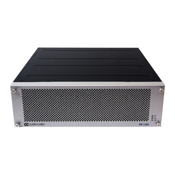
High-density analog media gateway
Hide thumbs
Also See for MediaPack Series:
- Quick manual (32 pages) ,
- Hardware installation manual (62 pages) ,
- Manual (8 pages)

Related Manuals for AudioCodes MediaPack Series


Summary of Contents for AudioCodes MediaPack Series
- Page 1 Hardware Installation Manual AudioCodes MediaPack Analog Gateway Series MP-1288 High-Density Analog Media Gateway Version x.y...
- Page 2 Please contact your local recycling authority for disposal of this product. Customer Support Customer technical support and services are provided by AudioCodes or by an authorized AudioCodes Service Partner. For more information on how to buy technical support for AudioCodes products and for contact information, please visit our website at https://www.audiocodes.com/services-support/maintenance-and-support...
- Page 3 Notice MP-1288 | Hardware Installation Manual The Ethernet port interface cabling must be shielded and routed only indoors. The device must be connected to a grounded power outlet. Routing of FXS telephony cables: Routing FXS telephony cables outdoors can be done only in conjunction with a three-electrode Gas Discharge Tube (GDT) rated at 350V located at the entry point of the two-wire into the building, and properly grounded.
- Page 4 Notice MP-1288 | Hardware Installation Manual Document Revision Record LTRT Description 28020 Initial document release. 28021 Cable anchor clip for power cord; adding FXS blade procedure (removing connector covers). 28022 Physical dimensions updated; warning bulletin for 19-inch rack cabinet. 28023 AC power cable warning (Japanese).
-
Page 5: Table Of Contents
5 Cabling the Device Grounding and Surge Protection Connecting Ethernet Interfaces Connecting FXS Interfaces Connecting FXS Interfaces using AudioCodes FXS Patch Panel Connecting FXS Interfaces using Centronics Cable Connecting FXS Interfaces Directly to an MDF Connecting the FXS Analog Lifeline... - Page 6 Content MP-1288 | Hardware Installation Manual Adding an FXS Blade Replacing the CPU Module Replacing Power Supply Modules - vi -...
-
Page 7: Introduction
CHAPTER 1 Introduction MP-1288 | Hardware Installation Manual Introduction This document provides a hardware description of AudioCodes MP- 1288 Analog Media Gateway (hereafter referred to as device) and step-by-step procedures for mounting and cabling the device. The device supports the following: ■... -
Page 8: Unpacking The Device
For AC-powered models: 2 x AC power cords ● For DC-powered models: 2 x DC terminal blocks ● 1 x grounding lug Check, retain and process any documents. If there are any damaged or missing items, notify your AudioCodes sales representative. - 2 -... -
Page 9: Physical Description
CHAPTER 3 Physical Description MP-1288 | Hardware Installation Manual Physical Description This section provides a physical description of the device. Physical Dimensions and Operating Environment The device's physical dimensions and operating environment are listed in the following table: Table 3-1: Physical Dimensions and Operating Environment Physical Description Specification... -
Page 10: Led Descriptions
CHAPTER 3 Physical Description MP-1288 | Hardware Installation Manual Table 3-2: Front Panel Description Item Label Description Fan Tray cover. For more information, see Fan Tray page 6 . SYS / TEL / PWR / Front-panel LEDs. For more information, see Descriptions below . -
Page 11: Pwr Led
CHAPTER 3 Physical Description MP-1288 | Hardware Installation Manual Color State Description ■ During booting up phase ■ During normal operation, indicating normal FXS blade operation Orange At least one DSP hasreached the high temperature threshold. LED lit as a result of one of the following: ■... -
Page 12: Fan Tray
CHAPTER 3 Physical Description MP-1288 | Hardware Installation Manual Fan Tray The device provides a Fan Tray module, located on the front panel, which is concealed by a fan tray cover. The Fan Tray module contains six individual fans which cool the device's internal components to maintain an acceptable operating temperature inside the chassis. -
Page 13: Rear Panel Description
CHAPTER 3 Physical Description MP-1288 | Hardware Installation Manual Figure 3-4: Fan Tray Cover The Fan Tray provides a LED indicating the operating status of the Fan Tray module. For more FAN LED on page 5 . information, see During system operation, the inner ambient temperature is continuously monitored. Upon excessive temperature conditions,... -
Page 14: Cpu Module
CHAPTER 3 Physical Description MP-1288 | Hardware Installation Manual Table 3-7: Rear Panel Description Item # Label Description CPU module providing the central processing unit and various network port interfaces. For more information, CPU Module below . PS1 / PS2 Power Power Supply modules. -
Page 15: Fxs Blades
CHAPTER 3 Physical Description MP-1288 | Hardware Installation Manual Item # Label Description ■ Half- and full-duplex modes ■ Auto-negotiation ■ Straight or crossover cable detection The ports provide LEDs to indicate Ethernet status. For more information, see Ethernet LEDs on page 14 . Reset pinhole button for resetting the device and restoring factory defaults : ■... - Page 16 CHAPTER 3 Physical Description MP-1288 | Hardware Installation Manual Figure 3-7: FXS Blade Showing Three FXS Telco Connectors The chassis slot assignment for the FXS blades is shown in the following figure (front panel). Note that the slot labels (S1, S2, S3 and S4) are located on the rear panel. Figure 3-8: Chassis Slot Assignment for FXS Blades (Front Panel) The FXS channel (port) number range of each FXS connector on an FXS blade is indicated by...
- Page 17 CHAPTER 3 Physical Description MP-1288 | Hardware Installation Manual Table 3-9: FXS Port Specifications Specification Description Analog The FXS blade supports analog lifeline (PSTN Fallback). For more Lifeline information, see Connecting the FXS Analog Lifeline on page 30 . (PSTN Fallback) Interface FXS connection via 50-pin CHAMP connector Type In-band signaling DTMF (TIA 464B)
-
Page 18: Power Supply Module
CHAPTER 3 Physical Description MP-1288 | Hardware Installation Manual Specification Description Tones Distinctive By frequency (15-100 Hz) and cadence patterns Ringing Message DC voltage generation (TIA/EIA-464-B); V23 FSK data; Stutter dial tone Waiting Indication (MWI) Power Supply Module The device can be powered from an AC or a DC power source. The type of power depends on your ordered hardware configuration. -
Page 19: Dc Power Supply Module
CHAPTER 3 Physical Description MP-1288 | Hardware Installation Manual Item Description Power cord anchor clip. 3-Prong power inlet. LED for indicating power status. For more information, see Power Supply LED page 16 . Handle for extracting and installing module. The two Power Supply modules installed in the chassis must be of the same hardware revision. -
Page 20: Led Descriptions
CHAPTER 3 Physical Description MP-1288 | Hardware Installation Manual LED Descriptions This section describes the LEDs on the rear panel of the chassis. Ethernet LEDs Each Ethernet port on the CPU module provides a LED (located on its left) which indicates network connectivity status, as described in the following table. - Page 21 CHAPTER 3 Physical Description MP-1288 | Hardware Installation Manual panel and the other LED on its rear panel to the left of the left-most FXS port (labeled FXS 49- 72), as shown in the following figures: Figure 3-12: FXS LED Location on Front Panel per FXS Blade Figure 3-13: FXS LED Location on Rear Panel per FXS Blade Table 3-14: FXS LEDs Description Color...
-
Page 22: Power Supply Led
CHAPTER 3 Physical Description MP-1288 | Hardware Installation Manual Power Supply LED The Power Supply module, located on the chassis rear panel, provides a LED which indicates the operating status of the module, as described in the following table. Table 3-15: Power Supply Module LED Description Color State Description... -
Page 23: 19-Inch Rack Mounting
CHAPTER 4 19-Inch Rack Mounting MP-1288 | Hardware Installation Manual 19-Inch Rack Mounting The device is designed to be mounted in a standard 19-inch rack. This is done by attaching it to the rack's posts using front-mounting brackets (supplied). At least two people are required to mount the device in the 19-inch rack. Avertissements: Au moins deux personnes sont nécessaires pour monter l’appareil dans le bâti 19 pouces. - Page 24 CHAPTER 4 19-Inch Rack Mounting MP-1288 | Hardware Installation Manual Figure 4-1: Attaching Mounting Brackets to Chassis With two people, lift the chassis into the rack from the front of the rack. Hold the chassis for support while the second person positions the chassis in the rack so that the front-mounting brackets are flush against the front-rack posts and that the holes of the front-mounting brackets aligned with the holes on the front-rack post, as shown in the following figure:...
-
Page 25: Cabling The Device
CHAPTER 5 Cabling the Device MP-1288 | Hardware Installation Manual Cabling the Device This section describes how to cable the device: ■ Connecting to earth / ground – see Grounding and Surge Protection below ■ Connecting Ethernet Interfaces on page 21 Connecting to the LAN – see ■... - Page 26 CHAPTER 5 Cabling the Device MP-1288 | Hardware Installation Manual Figure 5-1: Stripped Grounding Wire Using a Philips-head screwdriver, remove the two screws and their spring washers for attaching the grounding lug, located on the chassis' rear panel as shown in the following figure: Figure 5-2: Removing Screws and Washers...
-
Page 27: Connecting Ethernet Interfaces
CHAPTER 5 Cabling the Device MP-1288 | Hardware Installation Manual Connect the other end of the grounding wire to the building protective earth. This should be in accordance with the regulations enforced in the country in which the device is installed. Connecting Ethernet Interfaces The device provides two 100/1000Base-T Gigabit Ethernet ports (RJ-45) for connecting to the IP network (e.g., LAN). -
Page 28: Connecting Fxs Interfaces
CHAPTER 5 Cabling the Device MP-1288 | Hardware Installation Manual Figure 5-5: Connecting the LAN Ports Connect the other end of the cable to your network. For 1+1 Ethernet port redundancy, repeat steps 1 through 2 for the standby port. Make sure that you connect each port to a different network (but in the same subnet). - Page 29 AudioCodes orderable FXS Patch Panel (see AudioCodes FXS Patch Panel on the next page ) ● AudioCodes orderable Centronics cable connector (10 m) to open leads, which needs to be connected to a distribution panel (see Connecting FXS Interfaces using Centronics Cable on page 28 )
-
Page 30: Connecting Fxs Interfaces Using Audiocodes Fxs Patch Panel
. Connecting FXS Interfaces using AudioCodes FXS Patch Panel You can purchase AudioCodes' FXS Patch Panel (shown in the following figure) to connect the FXS interfaces to FXS equipment. The patch panel can be mounted in a 19-inch rack using integrated mounting brackets and provides a 2-meter (78.7 in.) extension cable with a 50-pin... - Page 31 CHAPTER 5 Cabling the Device MP-1288 | Hardware Installation Manual Figure 5-7: Orderable FXS Patch Panel ➢ To connect the FXS interfaces using the FXS Patch Panel: Mount the Patch Panel in a 19-inch rack, using the integrated mounting brackets located on either side of the Patch Panel.
- Page 32 CHAPTER 5 Cabling the Device MP-1288 | Hardware Installation Manual Figure 5-8: Mounting Patch Panel in Rack Connect the Patch Panel's 50-pin male connector to one of the FXS blade's 50-pin female Telco connectors located on the chassis' rear panel, and secure the connector with the two captive screws located on either side of the connector, using a flat-head screwdriver: Figure 5-9: Connecting 50-Pin Telco Connector to Port on FXS Blade...
- Page 33 CHAPTER 5 Cabling the Device MP-1288 | Hardware Installation Manual Figure 5-10: Connecting Analog Equipment to FXS Patch Panel For outdoor FXS cabling installations, you must install additional power surge protection as illustrated in the following figure. For indoor FXS cabling installations, there is no need for primary lightning protection usage.
-
Page 34: Connecting Fxs Interfaces Using Centronics Cable
MP-1288 | Hardware Installation Manual Connecting FXS Interfaces using Centronics Cable You can purchase AudioCodes' Centronics-type cable connector, as shown in the following figure, to connect the FXS interfaces to FXS equipment. The 10-meter cable (32.8 ft.) provides a 50-pin male Telco connector on one end and open leads on the other end, which need to be connected to your patch panel or distribution frame. -
Page 35: Connecting Fxs Interfaces Directly To An Mdf
CHAPTER 5 Cabling the Device MP-1288 | Hardware Installation Manual Terminate the wires on the other end of the cable to your patch panel or distribution frame. The wires are grouped in pairs with labels indicating the FXS channels. Make sure that you connect the wires according to the correct port channels as labelled on the wires. -
Page 36: Connecting The Fxs Analog Lifeline
CHAPTER 5 Cabling the Device MP-1288 | Hardware Installation Manual Figure 5-14: Connecting FXS Interfaces Directly to MDF Connecting the FXS Analog Lifeline The device supports PSTN Fallback (analog Lifeline), whereby it automatically connects an FXS port (Lifeline extension or phone) to the PSTN / PBX upon a power outage. This enables the phone to make and receive calls to and from the PSTN respectively, instead of the IP network. - Page 37 CHAPTER 5 Cabling the Device MP-1288 | Hardware Installation Manual Lifeline interface providing the connection to the PSTN / PBX. For example, for FXS connector labeled FXS 1-24, channel 1 is the Lifeline extension and channel 25 is the Lifeline interface for the PSTN / PBX.
-
Page 38: Connecting The Serial Interface To A Computer
CHAPTER 5 Cabling the Device MP-1288 | Hardware Installation Manual Figure 5-16: Cabling FXS Lifeline Connecting the Serial Interface to a Computer The RS-232 interface port is used to access the command line interface ( CLI) for serial communication. The device provides an RS-232 serial interface port on its rear panel. The RS-232 interface port is used to access the device's command line interface (CLI). - Page 39 CHAPTER 5 Cabling the Device MP-1288 | Hardware Installation Manual RJ-45 DB-9 Female used Internally used used Receive Data (RXD) Transmit Data (TXD) Ground (GND) Ground (GND) Internally used used ➢ To connect the serial interface port to a computer: Connect the RJ-45 connector, at one end of the cable, to the device's serial port (labeled |0|0|), located on the CPU module on the rear panel.
-
Page 40: Connecting To Power
CHAPTER 5 Cabling the Device MP-1288 | Hardware Installation Manual Connecting to Power The device can be powered from an AC or a DC power source, depending on ordered hardware configuration. AC Power Supply The device provides two hot-swappable Power Supply modules for load-sharing and power redundancy in case of failure in one of the modules. - Page 41 CHAPTER 5 Cabling the Device MP-1288 | Hardware Installation Manual Figure 5-19: Swinging Cable Anchor Clip away from Power Inlet Plug the female end of the AC power cord (supplied) into the power inlet. Figure 5-20: Connecting to Power Secure the power cord to the power inlet by providing strain relief, using the cable anchor clip.
-
Page 42: Dc Power Supply
CHAPTER 5 Cabling the Device MP-1288 | Hardware Installation Manual DC Power Supply The device houses two hot-swappable Power Supply modules, providing 1+1 load-sharing and power redundancy in case of a Power Supply module failure. Table 5-6: DC Power Specifications Physical Specification Value Input Ratings Dual universal power supply 40-60 VDC, 32A max... - Page 43 CHAPTER 5 Cabling the Device MP-1288 | Hardware Installation Manual Identify the polarity (negative and positive) of the two DC power feed wires. Polarity of power feed wires are typically color-coded, where red is positive (RTN) and black is negative (-48VDC). Insert the exposed wire of one of the two DC-input power source wires into the correct opening (according to polarity) on the terminal block plug (supplied), as shown in the following figure.
- Page 44 CHAPTER 5 Cabling the Device MP-1288 | Hardware Installation Manual Figure 5-23: Wired DC Power Supply Modules Connect the DC power leads to a 48-VDC power source. - 38 -...
-
Page 45: Hardware Maintenance
CHAPTER 6 Hardware Maintenance MP-1288 | Hardware Installation Manual Hardware Maintenance The device is designed as a modular chassis and allows you to order any module as a Field Replacement Unit (FRU). This section describes the procedures for replacing modules. Ensure that all unoccupied module chassis slots are covered with blank panels. This allows optimal internal airflow pressure within the chassis. - Page 46 CHAPTER 6 Hardware Maintenance MP-1288 | Hardware Installation Manual ● N’opérez pas l’appareil sans module de Caisse de ventilateur ! Avant de remplacer le module de Caisse de ventilateur, assurez-vous que vous avez le module de remplacement en main. ● Avant de retirer le module de Caisse de ventilateur et une fois l’appareil mis hors tension, les lames risquent de continuer à...
-
Page 47: Replacing The Air Filter
CHAPTER 6 Hardware Maintenance MP-1288 | Hardware Installation Manual Figure 6-3: Location of Screws on Fan Tray Module Grip the handle of the Fan Tray module where you removed the screws in the previous step, and then gently but firmly pull the module away from the chassis so that it disconnects from the connector providing it with power: Figure 6-4: Location of Handles and Removing Fan Tray Module... - Page 48 The device's components may be damaged due to a dirty or blocked air filter. ● Replace the air filter only with an air filter purchased from AudioCodes. ● Before removing the air filter, make sure that you have the replacement air filter on hand so that you can replace it immediately.
-
Page 49: Replacing Fxs Blades
CHAPTER 6 Hardware Maintenance MP-1288 | Hardware Installation Manual Figure 6-7: Removing Air Filter from Air Filter Cover Insert the new filter into the enclosure of the air filter cover. Attach the air filter cover back on the Fan Tray cover by using the two spring-loaded captive screws (see the figure in Step 2). - Page 50 CHAPTER 6 Hardware Maintenance MP-1288 | Hardware Installation Manual Figure 6-8: Removing 50-Pin Telco Connector On the rear panel, remove all the hex-standoff screws securing the FXS blade to the chassis, using a 3/16-in. hex-head nut driver. Each FXS port has two hex-standoff screws (7 mm) on either side and therefore, you need to remove all six screws: Figure 6-9: Removing Hex Standoff Screws on Rear Panel (Example FXS Blade S4)
- Page 51 CHAPTER 6 Hardware Maintenance MP-1288 | Hardware Installation Manual Figure 6-10: Loosening Screws on FXS Blade on Front Panel Gently pull the FXS blade out of the chassis slot: Figure 6-11: Removing FXS Blade from Chassis Slot on Front Panel Install the new FXS blade: Hold the blade on the front where the captive screws are located, making sure that you do not touch the blades electrical components.
- Page 52 CHAPTER 6 Hardware Maintenance MP-1288 | Hardware Installation Manual Figure 6-12: Slot's Guiding Rails for FXS Blade On the rear panel, secure the FXS blade to the chassis by inserting the hex-standoff screws (see the figure in Step 1.d for location of screws), using a 3/16-in. hex-head nut driver.
- Page 53 CHAPTER 6 Hardware Maintenance MP-1288 | Hardware Installation Manual Figure 6-13: Inserting Screwdriver into Cover Plate Hole Figure 6-14: Removing Cover Plates On the front panel, remove the Fan Tray cover and Fan Tray module, as described in Replacing the Fan Tray Module on page 39 .
- Page 54 CHAPTER 6 Hardware Maintenance MP-1288 | Hardware Installation Manual the inner guiding rule, as shown in the following figure. Slide the FXS blade into the slot until it has engaged with the chassis backplane: Figure 6-15: Slot's Guiding Rails for FXS Blade On the rear panel, secure the FXS blade to the chassis by inserting the hex-standoff screws, using a 3/16-in.
- Page 55 CHAPTER 6 Hardware Maintenance MP-1288 | Hardware Installation Manual Figure 6-17: Tightening Captive Screws of FXS Blade on Front Panel On the rear panel, tighten the hex-standoff screws on each Telco connector of the FXS blade, using a 3/16-in. hex-head nut driver. On the front panel, re-install the Fan Tray module and Fan Tray cover, as described in Replacing the Fan Tray Module on page 39 .
- Page 56 CHAPTER 6 Hardware Maintenance MP-1288 | Hardware Installation Manual Figure 6-18: Removing CPU Module on Rear Panel Install the new CPU module: Hold the front part of the module with one hand and place your other hand under the module to support it. Orientate the module as shown above and align the module with the guiding rails in the chassis slot.
- Page 57 CHAPTER 6 Hardware Maintenance MP-1288 | Hardware Installation Manual Replacing Power Supply Modules The following procedure describes how to replace a Power Supply module. The Power Supply modules are hot-swappable. Therefore, if you are replacing only one module, you can leave the second module connected to the power source.
- Page 58 CHAPTER 6 Hardware Maintenance MP-1288 | Hardware Installation Manual Figure 6-19: Handle and Release Latch on Power Supply Module (Example using AC Module) Place your other hand under the Power Supply module for support and then slide it completely out of the chassis. Avoid touching the top of the module; it may be hot from being in the chassis: ...
- Page 59 CHAPTER 6 Hardware Maintenance MP-1288 | Hardware Installation Manual This page is intentionally left blank. - 53 -...
- Page 60 ©2020 AudioCodes Ltd. All rights reserved. AudioCodes, AC, HD VoIP, HD VoIP Sounds Better, IPme- dia, Mediant, MediaPack, What’s Inside Matters, OSN, SmartTAP, User Management Pack, VMAS, VoIPerfect, VoIPerfectHD, Your Gateway To VoIP, 3GX, VocaNom, AudioCodes One Voice, AudioCodes Meeting Insights, AudioCodes Room Experience and CloudBond are trademarks or registered trade- marks of AudioCodes Limited.
Need help?
Do you have a question about the MediaPack Series and is the answer not in the manual?
Questions and answers